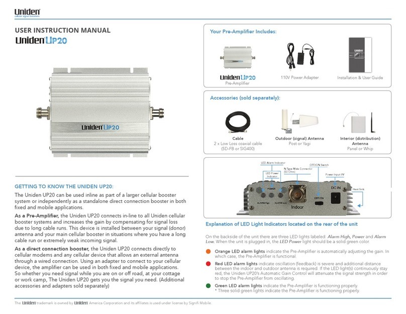
DH Instruments GB-K-152 User manual

© 1998 - 2000 DH Instruments, Inc.
GB-K-75 and GB-K-152
Gas Booster Packages
For PPCK+ Pressure Controller/Calibrator
Operation and Maintenance Manual

GB-K Gas Booster Package Operation and Maintenance Manual
© 1998 - 2000 DH Instruments, Inc.
This equipment described in this manual is designed and manufactured for the intended purpose of
generating high pressure gas and regulating two independent gas output pressures. Certain precautions
need to be followed during installation and operation of this device. Reading and understanding the
material is essential to the safe and correct operation of the unit.
Pressurized equipment is potentially dangerous. The equipment described in this manual generates and
controls very high gas pressures. It should not be operated by anyone who has not thoroughly familiarized
themselves with this manual. Additional training in general and pressure specific safety procedures will
help assure protection from harm or damage to personnel or property. Responsibility for the proper and
safe operation of this instrument rests with the user.
Do not use oxygen. This instrument is not compatible with the use of oxygen. Hydrocarbon elastomers
and lubricants are present.
High pressure liquids and gases are potentially hazardous. Energy stored in these liquids and gases can
be released unexpectedly and with extreme force. High pressure systems should be assembled and
operated only by personnel who have been instructed in proper safety practices.
©1998 ~ 2000, DH Instruments, Inc. All rights reserved.
Information in this document is subject to change without notice. No part of this document may be reproduced or
transmitted in any form or by any means, electronic or mechanical, for any purpose, without the express written
permission of DH Instruments, Inc. 4765 East Beautiful Lane Phoenix AZ 85044-5318 USA.
DH Instruments makes every effort to ensure the accuracy and quality of it’s published materials; however,
no warranty, expressed or implied, is provided. DH Instruments disclaims any responsibility or liability for any direct
or indirect damages resulting from the use of the information in this manual or products described in it. Mention of
any product or brand does not constitute an endorsement by DH Instruments of that product or brand. This manual
was originally composed in English and was subsequently translated into other languages. The fidelity of subsequent
translations cannot be guaranteed. In case of conflict between the English version and another language version,
the English version predominates.
DH Instruments, DH , DHI, PPC, PPCK+, PPC2+, RPM3 and CalTool are trademarks, registered and otherwise.
Swagelok is a registered trademark of the Swagelok Company.
Teflon is a registered trademark of the 3M Corporation.
Document No. 550082a
000822
Printed in the USA.

GB-K Gas Booster Package Operation and Maintenance Manual
Page i © 1998 - 2000 DH Instruments, Inc.
T
TA
AB
BL
LE
E
O
OF
F
C
CO
ON
NT
TE
EN
NT
TS
S
TABLE OF CONTENTS................................................................................i
TABLES................................................................................................... iii
FIGURES ................................................................................................. iii
ABOUT THIS MANUAL.............................................................................. iv
1. INTRODUCTION.................................................................................... 1
1.1 PRODUCT OVERVIEW .............................................................................................................................1
1.2 LOCATION AND DESCRIPTION OF THE COMPONENTS......................................................................1
1.3 SYSTEM SCHEMATIC ..............................................................................................................................4
1.4 SPECIFICATIONS .....................................................................................................................................5
2. INSTALLATION..................................................................................... 7
2.1 UNPACKING AND INSPECTION ..............................................................................................................7
2.2 SITE REQUIREMENTS..............................................................................................................................8
2.3 INSTALLATION AND SETUP ...................................................................................................................9
3. OPERATION ....................................................................................... 13
3.1 GENERAL OPERATING PRINCIPLE AND INFORMATION...................................................................13
3.1.1 PNEUMATICALLY OPERATED GAS BOOSTER PUMP (6)..........................................................................13
3.1.2 VALVE..............................................................................................................................................................14
3.1.3 VOLUME CYLINDER (ACCUMULATOR) .......................................................................................................14
3.1.4 REGULATORS.................................................................................................................................................14
3.1.5 GAUGES ..........................................................................................................................................................15
3.2 SETTING LOW PRESSURE OUTPUT ....................................................................................................15
3.2.1 INCREASING PRESSURE ..............................................................................................................................15
3.2.2 DECREASING PRESSURE .............................................................................................................................16
3.3 SETTING HIGH PRESSURE OUTPUT UP TO SUPPLY PRESSURE....................................................16
3.3.1 INCREASING PRESSURE ..............................................................................................................................16
3.3.2 DECREASING PRESSURE .............................................................................................................................17
3.4 SETTING HIGH PRESSURE OUTPUT ABOVE SUPPLY PRESSURE..................................................17
3.4.1 SETTING BOOSTER DRIVE PRESSURE.......................................................................................................17
3.4.2 INCREASING PRESSURE ..............................................................................................................................18
3.4.3 DECREASING PRESSURE .............................................................................................................................19
4. MAINTENANCE AND ADJUSTMENTS ................................................... 21
4.1 MAINTENANCE.......................................................................................................................................21

GB-K Gas Booster Package Operation and Maintenance Manual
© 1998 - 2000 DH Instruments, Inc. Page ii
5. TROUBLESHOOTING .......................................................................... 23
5.1 GENERAL INFORMATION......................................................................................................................23
5.2 BOOSTER WILL NOT RUN.....................................................................................................................23
5.3 BOOSTER RUNS TOO SLOWLY ...........................................................................................................24
5.4 PRESSURE GENERATES TOO SLOWLY OR NOT AT ALL.................................................................24
5.5 BOOSTER CONTINUOUSLY RUNS.......................................................................................................25
5.6 CANNOT ACHIEVE PRESSURE (LP & HP) ...........................................................................................25
5.6.1 LOW PRESSURE.............................................................................................................................................25
5.6.2 HIGH PRESSURE ............................................................................................................................................26
5.7 LEAKS .....................................................................................................................................................26
5.8 GAS CONTINUOUSLY VENTS THROUGH EXHAUST MUFFLER........................................................27
6. WARRANTY STATEMENT .................................................................... 29
6.1 WARRANTY STATEMENT......................................................................................................................29

GB-K Gas Booster Package Operation and Maintenance Manual
Page iii © 1998 - 2000 DH Instruments, Inc.
T
TA
AB
BL
LE
ES
S
Table 1. GB-K-75 or GB-K-152 Parts List ............................................................................................... 7
Table 2. DHI Authorized Service Providers........................................................................................... 30
F
FI
IG
GU
UR
RE
ES
S
Figure 1. Pneumatic Connection Panel .................................................................................................... 1
Figure 2. Control Panel............................................................................................................................. 2
Figure 3. System Schematic..................................................................................................................... 4

GB-K Gas Booster Package Operation and Maintenance Manual
© 1998 - 2000 DH Instruments, Inc. Page iv
A
AB
BO
OU
UT
T
T
TH
HI
IS
S
M
MA
AN
NU
UA
AL
L
Manual Conventions
(CAUTION) is used in throughout the manual to identify user warnings and cautions.
(NOTE) is used throughout the manual to identify operating and applications advice and
additional explanations.

GB-K Gas Booster Package Operation and Maintenance Manual
Page 1 © 1998 - 2000 DH Instruments, Inc.
1
1.
.
I
IN
NT
TR
RO
OD
DU
UC
CT
TI
IO
ON
N
1.1 PRODUCT OVERVIEW
GB-K-75 and GB-K-152 are gas booster packages intended to be used to provide the gas pressure
supplies required by DHI PPCK+ controller/calibrators for high pressure gas.
Both models include a pneumatically driven, piston type, self-cycling gas booster with regulated
output to provide the PPCK+ high pressure supply. The gas booster boosts a lower pressure (3.5
MPa minimum), generally supplied from a bottle to higher pressure. The high pressure gas is stored
in an accumulator volume to assure stable supply to the PPCK+. GB-K-75 has a maximum output
pressure of 50 MPa (7 500 psi) and is used with PPCK+ A3000 and A6000. GB-K-152 has a
maximum output of 76 MPa (11 000 psi) and is used with PPCK+ A10000.
Both models also include an independent low pressure regulator and gauge to supply the PPCK+
drive air requirement.
With a GB-K gas booster, all of the PPCK+ pressure supply requirements are taken care of in one
simple package requiring on the connection of a clean gas source of 2 MPa (300 psi) or higher clean
compressed gas source and a shop air supply to power the booster.
1.2 LOCATION AND DESCRIPTION OF THE COMPONENTS
Figure 1. Pneumatic Connection Panel
3
2
1

GB-K Gas Booster Package Operation and Maintenance Manual
© 1998 - 2000 DH Instruments, Inc. Page 2
PNEUMATIC CONNECTION PANEL:
1. High Pressure Outlet Fitting: a stainless steel DH 200 female coned end fitting used to
connect the high pressure output to a point-of-use (usually the PPCK+ SUPPLY port).
DH200 F is a gland and collar type fitting for coned and left hand threaded 1/4 in. (6.35 mm) OD
tube, equivalent to AE SF250C, HIP LF4, etc. DO NOT USE INCORRECT FITTINGS; DAMAGE TO
THE FITTING AND DANGER TO THE OPERATOR COULD RESULT.
2. Low Pressure Outlet Fitting: a stainless steel 1/8 in. NPT female fitting used to connect the low
pressure output to a point-of-use (usually the PPCK+ DRIVE IN port).
3. Supply Inlet Fitting: a stainless steel 1/8 in. NPT female fitting used to connect an external
source of high pressure gas. This is the gas pressure that will be boosted to obtain very high
pressure at the High Pressure Outlet and regulated to provide low pressure at the Low
Pressure Outlet.
Figure 2. Control Panel
8
7
9
1
0
11
12
4
5
6
13

GB-K Gas Booster Package Operation and Maintenance Manual
Page 3 © 1998 - 2000 DH Instruments, Inc.
CONTROL PANEL:
4. High Pressure Outlet Gauge: a 4 in. (102 mm) diameter dial gauge constructed of stainless
steel with a range of zero to 70 MPa (10 000 psig) or zero to 103 MPa (15 000 psig). It is used to
indicate the output of the High Pressure Outlet Regulator (7).
5. Low Pressure Outlet Gauge: a 2 in. (51 mm) diameter dial gauge constructed of stainless steel
with a range of zero to 300 psig (2 MPa). It is used to indicate the output of the Low Pressure
Outlet Regulator (12).
6. Pneumatically Operated Gas Booster Pump: a Pascal press utilizing two pistons connected
together on the same axis having a nominal area ratio of either 75:1 or 152:1. The booster is a
two-stroke, single stage reciprocating pump.
7. High Pressure Outlet Regulator: a self-venting type regulator constructed of 303 stainless
steel, Kel-F, Buna-N, and Teflon wetted materials with an outlet pressure control range of 1.5
MPa (200 psi) to 50 MPa (7 500 psig) or 76 MPa (11 000 psig).
8. Shop Drive Air Inlet Fitting: a brass fitting with a 1/4 in. NPT female connection.
9. Shop Drive Air Pressure Gauge: a 1.5 in. (38 mm) diameter dial gauge constructed of brass
with a range of zero to 1.4 MPa (200 psig). It is used to indicate the output pressure of the Shop
Drive Air Regulator (10).
10. Shop Drive Air Regulator: a self-venting type regulator constructed of 316 stainless steel and
nylon wetted components with an outlet pressure control range of 0.9 MPa (125 psig).
Maximum supply pressure is 1 MPa (150 psig). The control knob is pulled out to make
adjustments; pushed in to lock into position. To prevent accidental pressure changes the knob
can easily be removed (pulled off).
11. Shop Drive Air Shut-off Valve: a brass ball-type, shut-off valve with a 90°full turn operation.
It is used to prevent flow of shop drive air to the booster. This valves turns the booster on and
off.
12. Low Pressure Outlet Regulator: a non-venting regulator constructed of aluminum, Viton,
stainless steel and Nylatron wetted materials with an outlet pressure control range of 0.15 to
1.25 MPa (20 to 180 psig). Maximum pressure supply is 20 MPa (3 000 psig).
13. Drive Air Exhaust Muffler: a painted aluminum tube with vent slits, 1/2 in. NPT female
connection fittings and noise reduction material inside. Used to muffle the noise of the booster
drive air exhaust.

GB-K Gas Booster Package Operation and Maintenance Manual
© 1998 - 2000 DH Instruments, Inc. Page 4
1.3 SYSTEM SCHEMATIC
1. Drive Air Gauge 8. Low Pressure Outlet Gauge
2. SHOP DRIVE AIR INLET Port 9. HIGH PRESSURE OUTLET Port
3. Drive Air Regulator 10. High Pressure Outlet Gauge
4. Drive Air Shut-Off Valve 11. HIGH PRESSURE ADJUST Regulator
5. SUPPLY INLET Port 12. Volume Cylinder (Accumulator)
6. LOW PRESSURE ADJUST Regulator 13. Booster Pump
7. LOW PRESSURE OUTLET Port
Figure 3. System Schematic
4
5
6
7
8
10
12
1
3
1
2
311 9

GB-K Gas Booster Package Operation and Maintenance Manual
Page 5 © 1998 - 2000 DH Instruments, Inc.
1.4 SPECIFICATIONS
Dimensions: 430 mm (17 in.) H x 355 mm (14 in.) W x 290 mm (11.5 in.) D
Weight: 18.6 kg (41 lbs)
Pressure Supply
Pressure Range:
Supply Flow Rates:
Cleanliness:
Shop Drive Air: 0.15 to 1 MPa (20 to 150 psi)
High Pressure Supply Gas: 2 to 20 MPa (300 to 3 000 psi)
Shop Drive Air: 425 to 2 125 slm (15 to 75 scfm)
High Pressure Supply Gas: 140 to 560 slm (5 to 20 scfm)
Shop Drive Air: 60 micron filtration @ 20 to 50 % relative humidity
High Pressure Supply Gas: 10 micron filtration with dew point of –20 °C
Pressure Connections: Shop Drive Air Supply Inlet: 1/4 in. NPT female
High Pressure Gas Supply Inlet: 1/8 in. NPT female
Low Pressure Outlet: 1/8 in. NPT female
High Pressure Outlet: DH 200 female (DH200 F is a gland and collar type
fitting for coned and left hand threaded 1/4 in. (6.35 mm) OD tube, equivalent
to AE SF250C, HIP LF4, etc.)
Output Pressure
Ranges:
Low Pressure Regulator: 0.14 to 1.2 MPa (20 to 180 psi)
High Pressure Regulator (GB-K-75): 0.35 to 50 MPa (200 to 7 500 psi)
High Pressure Regulator (GB-K-152): 0.35 to 86 MPa (200 to 11 000 psi)
Booster Piston Ration: 75:1 for GB-K-75
152:1 for GB-K-152
Due to a policy of continual product improvement, all specifications are subject to change without notice.

GB-K Gas Booster Package Operation and Maintenance Manual
© 1998 - 2000 DH Instruments, Inc. Page 6
N
NO
OT
TE
ES
S

GB-K Gas Booster Package Operation and Maintenance Manual
Page 7 © 1998 - 2000 DH Instruments, Inc.
2
2.
.
I
IN
NS
ST
TA
AL
LL
LA
AT
TI
IO
ON
N
2.1 UNPACKING AND INSPECTION
GB-K-75 and GP-K-152 are delivered enclosed in plastic film and secured by foam in place in a
corrugated box. All ports are plugged, the valve is closed and pressure regulators are set to zero.
Remove the instrument from the shipping box and plastic bag. Take care not to lose or discard the
accessories that are included.
Place the instrument at a convenient working height. Remove all plugs from the fittings and inspect
for damage and contamination. If damage is noted, report it to your Receiving Department for
appropriate action.
Inspect for any missing components or accessories using Table 1. Should any items be missing,
contact DHI or you local supplier.
Table 1. GB-K-75 or GB-K-152 Parts List
DESCRIPTION PART #
GB-K-75 Instrument or
GB-K-152
401092
401086
Accessories including:
1 Operation and Maintenance Manual 550082
Interconnections Kit: 401513
1 ea. Adaptor, DH200 M x 2T M (1/8 in. swage M) 400518
3 ea. Adaptor, 1/8 in. M x 2T M (1/8 in. swage M) 100319
200 cm 1/8 in. PFA tubing 101392-Z
200 cm 1/8 in. stainless steel tubing (0.125 in. x 0.055 in.) 101988-Z

GB-K Gas Booster Package Operation and Maintenance Manual
© 1998 - 2000 DH Instruments, Inc. Page 8
2.2 SITE REQUIREMENTS
Two sources of compressed gas are required to operate the instrument: 1) shop drive air supply to
power the booster; 2) high pressure gas that the booster will compress to higher pressures. Due to
the different flow rate and cleanliness requirements for each of these supplies, they should come
from two separate sources. It is not recommended that hazardous gases be used unless appropriate
precautions are taken.
1) Shop drive air supply:
The shop air drive supply powers the booster. The booster output is approximately 75 times the
drive air supply (GB-K-75) or 152 times the drive air supply (GB-K-152).
Shop drive air requirements are:
Pressure:
- For operation up to 25 MPa (3 500 psi) with GB-K-75: 0.4 MPa (60 psi) minimum
- For operation up to 50 MPa (7 500 psi) with GB-K-75: 0.7 MPa (100 psi) minimum
- For operation up to 50 MPa (7 500 psi) with GB-K-152: 0.4 MPa (60 psi) minimum
- For operation up to 76 MPa (11 000 psi) with GB-K-152: 0.5 MPa (75 psi) minimum
Flow rate:
- 425 slm (15 scfm) minimum
Cleanliness: Not critical, use 60 micron filter
Humidity: 20 to 50 % RH. Do not use dry gas. Do not use hazardous gases.
2) High pressure instrument gas supply:
High pressure instrument gas is boosted by the booster and supplied to the PPCK+ SUPPLY
port. It is also regulated down and supplied to the PPCK+ DRIVE IN port.
High pressure instrument gas supply requirements are:
Pressure:
- 2 MPa (300 psig) minimum, 20 MPa (3 000 psig) maximum
Flow rate:
- 140 slm (5 scfm) minimum
Cleanliness: Use clean, dry instrument grade gases only. Filtration of 10 micron and moisture
content of –20 °C is recommended.

GB-K Gas Booster Package Operation and Maintenance Manual
Page 9 © 1998 - 2000 DH Instruments, Inc.
2.3 INSTALLATION AND SETUP
Installation of the GB-K depends on the specific application. For a detailed description of the theory
of operation see Section 3.1. Refer to Section 2.2 before attempting installation.
The orientation of the instrument is of no consequence to its operation. It may be installed vertically,
horizontally or any combination of the two with no effect on performance or maintenance.
A variety of factors must be considered when determining where to locate the BP-K. Factors include,
but are not limited to:
•the high pressure being generated and associated safety concerns
•the source of gas supplies (shop drive air supply and high pressure instrument gas supply)
•noise levels
•vibration during use
•access to the unit for operation of the regulators and valve
•point of use of output pressures
•vents to atmosphere
To install the GB-K, follow the steps below:
nPlace the GB-K in the appropriate location. Use the attached mounting brackets to secure the
instrument to a fixed location if desired.
Due to the reciprocating nature of the instrument, it is advised that shock mounts be used when
rigidly mounting the GB-K.
oClose all three regulators (7), (10), and (12) by rotating the knobs counter-clockwise until no
spring force is felt.
The Shop Drive Air (10) and High Pressure Outlet (7) Regulators have a stop that prevents continued
counter-clockwise rotation.
The Low Pressure Outlet Regulator (12) does not have a stop and therefore will result in the removal of
the knob from the body if counter-clockwise rotation is continued beyond the shut-off point.
The Shop Drive Air Regulator (10) has a locking mechanism to prevent accidental adjustment.
To unlock, pull the knob up. The knob can be removed completely to make adjustment
tamper resistant.
pClose the Drive Air Shut-off Valve (11).
qConnect shop drive air supply to the 1/4 in. NPTF connection (9) of the Pressure Regulator
(labeled Shop Drive Air Supply on the System Schematic) using tubing rated for at least 1 MPa
(150 psig) working pressure.

GB-K Gas Booster Package Operation and Maintenance Manual
© 1998 - 2000 DH Instruments, Inc. Page 10
Maximum input pressure to the Shop Drive Air Regulator (10) is 0.9 MPa (130 psig). Pressures above
this level may result in a failure that could damage the instrument and/or cause personal injury.
Using connecting tubing rated for working pressures below 130 psig is not recommended.
The regulator housing is glass-filled nylon. To overtorque the Shop Drive Air Inlet Fitting (8) when
connecting drive air will result in damage to the regulator housing.
rConnect the instrument gas supply to the 1/8 in. NPTF fitting (3 – labeled Supply Inlet on
the panel) using tubing rated at 3 000 psig (20 MPa) working pressure.
Maximum input pressure to the Supply Inlet Fitting (3) is 20 MPa (3 000 psig). Pressure above this
level may result in a failure that could damage the instrument and/or cause personal injury.
Using connecting tubing rated below 20 MPa (3 000 psig) working pressure is not recommended.
Pressure present at the Supply Inlet Fitting (3) will be present at the inlet ports of both the High (7)
and Low (12) Pressure Regulators. Instrument gas supply is not stopped at the Pneumatically
Operated Gas Booster Pump (6) as may be expected. The check valves in the booster prevent flow in
the reverse direction of the source flow. To prevent gas pressure from reaching the point of use,
ensure the regulators are closed. See Point 2 and related NOTE above for regulator closure.
sConnect the 1/8 in. NPTF Low Pressure (LP) Outlet Fitting (2) to the point of use with tubing rated
for at least 180 psig (1.24 MPa) working pressure.
When using the GB-K with a PPCK+ Pressure Controller/Calibrator use the hardware provided in
the interconnect kit to:
- Install a 1/8 in. M x 2T (1/8 in. swage) adaptor in the GB-K Low Pressure Outlet.
- Install a 1/8 in. M x 2T (1/8 in. swage) adaptor in the PPCK+ DRIVE IN port.
- Use the desired length of 1/8 in. PFA tubing to connect the two adaptors together.
Using connecting tubing with a working pressure below 180 psig (1.24 MPa) may result in a failure in
the tubing that could cause damage to the instrument and/or cause personal injury.
If the Low Pressure Outlet is not being used, plug the fitting using a 1/8 in. NPTM plug.
tConnect the DH 200F High Pressure Outlet Fitting (1) to the point of use with the tubing rated for
at least 50 MPa (7 500) psig with GB-K-75 or 76 MPa (11 000 psig) with GB-K-152
working pressure.
When using the GB-K with a PPCK+ Pressure Controller/Calibrator use the hardware provided in
the interconnect kit to:
- Install a DH200 M x 2T (1/8 in. swage) adaptor in the GB-K High Pressure Outlet.
- Install a 1/8 in. M x 2T (1/8 in. swage) adaptor in the PPCK+ SUPPLY port.
- Use the desired length of 1/8 in. stainless steel tubing to connect the two adaptors together.
Be sure to very carefully clean the tube ends of metallic particles if the tube is shortened.

GB-K Gas Booster Package Operation and Maintenance Manual
Page 11 © 1998 - 2000 DH Instruments, Inc.
Using connecting tubing with a working pressure below the maximum rated output pressure may result
in a failure in the tubing that could cause damage to the instrument and/or cause personal injury.
If the High Pressure Outlet is not being used, plug the fitting.
uIf the shop drive air used to operate the GB-K is to be vented to a location other than where the
booster is being used or if the noise levels are to be reduced, proceed as follows:
Remove the Drive Air Exhaust Muffler (13). The Drive Air Exhaust Muffler (13) and booster
exhaust port are both 1/2 in. NPTF connected via a 1/2 in. NPT nipple. Therefore, the fitting
available for connection is a 1/2 in. NPT male (when using the nipple) or female (when not
using the nipple).
Connect a hose with an I.D. of at least 1/2 in. (13 mm) and maximum length of 50 ft.
(16 meters) to the booster fitting (1/2 in. NPT male or female). A hose length of greater than
50 ft (16 meters) can be used provided the I.D. of the hose is increased.
Connect the loose end of the hose to an appropriate termination point.

GB-K Gas Booster Package Operation and Maintenance Manual
© 1998 - 2000 DH Instruments, Inc. Page 12
N
NO
OT
TE
ES
S

GB-K Gas Booster Package Operation and Maintenance Manual
Page 13 © 1998 - 2000 DH Instruments, Inc.
3
3.
.
O
OP
PE
ER
RA
AT
TI
IO
ON
N
3.1 GENERAL OPERATING PRINCIPLE AND INFORMATION
Numerical references in this section refer to Figure 2.
The purpose of the GB-K is to provide two independent, regulated gas pressure outputs: 1) a low
pressure that is regulated down directly from the instrument high pressure gas supply; 2) a very high
pressure that is generated by the unit. The unit generates high pressure using a Pneumatically
Operated Gas Booster Pump (6), a Shop Drive Air Shut-off Valve (11), an accumulator volume (not
labeled), regulators (7), (10), (12), and gauges (4), (5), (9). Fittings on an attached panel provide
ports for supply input (3) and pressure outputs (1), (2). The system is contained in one compact unit
and is ready to operate once gas supplies are connected.
3.1.1 PNEUMATICALLY OPERATED GAS BOOSTER PUMP (6)
The booster pump is a Pascal press utilizing two pistons connected together on the same
axis having a normal area ration of 75:1 or 152:1. The booster is a two-stroke, single stage
reciprocating pump that generates gas pressures 75 or 152 times greater than the shop drive
air applied to the pump.
The pump operates automatically, provided shop drive air is supplied to the Shop Drive Air
Regulator (10) and the regulator is set to at least 140 kPa (20 psig). Operation is continuous
until the outlet pressure is 75 (GB-K-75) or 152 (GB-K-152) times the shop drive air pressure.
At this point, the opposing forces within the pump reach equilibrium and the pump stalls.
For example, using a GB-K-75 with the shop drive air pressure set to 0.35 MPa (50 psig), the
pump will run until the instrument gas pressure in the high pressure chamber reaches 75 x
0.35 = 26.3 MPa (3 750 psig).
1. The Shop Drive Air section (low pressure) consists of a piston, cylinder, air cycling valve,
pilot valve and vent section. This section provides the reciprocating action and
compression force needed to operate the booster and generate the high pressure gas.
Drive air is channeled to the appropriate side of the piston (compression or suction
stroke) by the air cycling valve. When the piston reaches full stroke, a pilot valve is
mechanically activated causing the air cycling valve to change position. Shop drive air is
routed to the opposite side of the piston reversing piston direction where a second pilot
valve is activated repeating the process.

GB-K Gas Booster Package Operation and Maintenance Manual
© 1998 - 2000 DH Instruments, Inc. Page 14
2. The instrument gas section (high pressure) consists of a small piston and an inlet/outlet
check valve assembly. The small piston moves forward and backward with the air
drive piston. During the suction stroke (backward movement), the outlet check valve
closes and the inlet check valve opens letting instrument gas enter the
compression chamber. During the compression stroke, the inlet check valve closes and
the outlet check valve opens letting compressed gas out of the pump.
The compression ratio of the high pressure piston is 25:1 (for both models).
Maximum output pressure is limited by the instrument gas supply pressure. For
example, with 2 MPa (300 psi) applied, maximum output pressure cannot exceed 2 x 25
= 50 MPa (7 500 psi).
3.1.2 VALVE
The shut-off valve is a ball-type, 90°turn valve. It is used to prevent flow of shop drive air to
the pump which shuts off the booster. This valve can be considered a booster
ON/OFF switch.
3.1.3 VOLUME CYLINDER (ACCUMULATOR)
The volume cylinder is a stainless steel chamber with an internal volume of about 50 cc.
Two fittings on the front face of the chamber provide inlet and outlet connections. It is used
to dampen pressure fluctuations during the reciprocating action of the pump and to provide a
reservoir of high pressure compressed gas.
3.1.4 REGULATORS
Three regulators are used in the system for control of the Shop Drive Air, Low Pressure
Outlet and High Pressure Outlet pressures.
All regulators should be adjusted in the increase direction due to hysteresis in the regulators.
Should a regulator be adjusted from a higher pressure to a lower pressure, once gas begins
to flow in the regulator the pressure ultimately set will be lower than that initially set. To avoid
this situation, set the initial pressure below the setpoint then adjust the regulator up to the
final setpoint.
1. The Shop Drive Air Pressure Regulator (10) is constructed of 316 stainless steel and
nylon wetted components. It is a self-venting type regulator with an outlet pressure
control range of 0 to 0.86 MPa (125 psig). Maximum inlet pressure is 1 MPa (50 psig).
The control knob is pulled out to make adjustments; pushed in to lock into position and
prevent accidental changes. It can also be pulled off for tamper resistance.
2. The Low Pressure Outlet Regulator (12) is constructed of aluminum, Viton, stainless
steel and Nylatron wetted materials. It is a non-venting type regulator with an outlet
pressure control range of 0.15 to 1.25 MPa (20 to 180 psig). Maximum inlet pressure is
20 MPa (3 000 psig).
3. The High Pressure Outlet Regulator (7) is constructed of 303 stainless steel, Kel-F,
Buna-N, and Teflon wetted materials. It is a venting type regulator with an outlet
pressure control range of 1.5 to 50 MPa (200 to 7 500 psig) or 2 to 76 MPa 300 to 11 000
psig. Maximum inlet pressure is equal to the maximum outlet pressure.
This manual suits for next models
1
Table of contents
Other DH Instruments Extender manuals
