GB-H-152 GAS BOOSTER PACKAGE OPERATION AND MAINTENANCE MANUAL
© 2008 DH Instruments, a Fluke Company Page 8
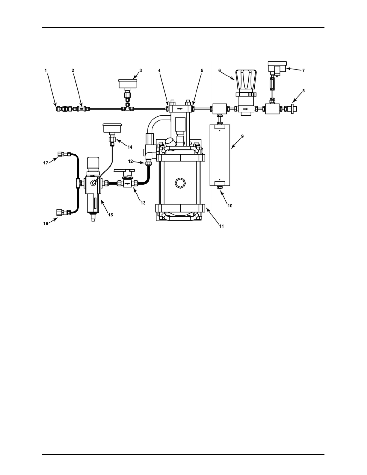
Pressure present at the SUPPLY IN port (5) will be present at the inlet port of the high
pressure adjust regulator (6). To prevent gas pressure from reaching the HIGH PRESSURE OUT
port (7), ensure that the high pressure adjust regulator is closed (backed off).
sIf desired, connect the 1/4 in. Swage DRIVE OUT connection (3) to the drive air point of
use with appropriately rated tubing.
If connecting to the PPCH-G DRIVE port, use the hardware provided in the GB-H-152
interconnect kit:
- Install the 1/8 in. M x 1/4 in. Swage adaptor in the PPCH-G DRIVE port.
- Remove the 1/4 in. Swage plug from the GB-H-152 DRIVE OUT port.
- Connect the PPCH-G DRIVE port to the GB-H-152 DRIVE OUT port with the 2 m. of
1/4 in. PFA tubing (cut the tube to a shorter length if desired). Use the supplied
Swage 1/4 in. nut and front and rear ferrules for the DRIVE OUT end of the tube.
Take care to align the ferrules correctly.
If the DRIVE OUT port is not being used, leave it capped.
tConnect the DH500F HIGH PRESSURE OUT port (7) to the high pressure gas point of
use with tubing of appropriate pressure rating (able to handle the maximum pressure that
the booster will generate). Working pressure rating should be at least 100 MPa (15 000)
psig for GB-H-152-70M and 140 MPa (20 000 psig) for GB-H-152-100M.
When using the GB-H-152 with a PPCH-G pressure controller/calibrator use the
hardware provided in the GB-H-152 interconnect kit:
Connect the 1.5 m, 1/8 in. nipple with DH500 tips between the GB-H-152 HIGH
PRESSURE OUT port and the PPCH-G SUPPLY port. The DH500 glands and
collars are delivered installed in the female ports. Remove the orange plastic plug,
slip the gland onto the DH500 tip, install the collar onto the DH500 tip and thread the
gland into the female DH500 fitting. Torque gland to 15 Nm (11 lb ft).
Do not bend tubing with radius less than 50 mm (2 in.) or pressure capacity may be reduced.
Using connecting tubing with a working pressure below the maximum pressure generated by
the booster may result in a failure in the tubing that could cause damage to the instrument
and/or cause personal injury.
uIf the shop drive air used to operate the GB-H-152 is to be vented to a location other than
where the booster is being used or to reduce the noise level of the operating booster,
proceed as follows:
Remove the drive air exhaust muffler (14). The drive air exhaust muffler (14) and
booster exhaust port are both 1/2 in. NPT F connected via a 1/2 in. NPT nipple.
Therefore, the fitting available for connection is a 1/2 in. NPT M (when using the
nipple) or female (when not using the nipple).
Connect a hose with an I.D. of at least 13 mm (1/2 in.) and maximum length of 16 m
(50 ft.) to the booster fitting (1/2 in. NPT M or F). A hose length of greater than 16 m
(50 ft) can be used provided the I.D. of the hose is increased.
Connect the loose end of the hose to an appropriate termination point.