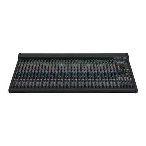
DHD RM3200D User manual

Chapter 1: Introduction
1 - 5
1. Introduction
The Digital Audio Mixer RM3200D is especially designed for applications in broadcasting. It
can equally be used for:
• Broadcast and pre-production for self operation studios or control rooms with one or
more studios
• Routing applications
• Audio workstations for editors
• Stations for sound editing and recording
• Video-postsynchronisation and cutting
Up to date workstations in the broadcasting business are often used by people who have
small or no technical background. Therefore, the control desk of RM3200D has been
especially designed for ease of use and accessability.
For the use in On-Air studios, the mixer can be integrated with automation systems.
Optional motor faders can also be used.
RM3200D is the ideal mixer for computer aided systems for sound editing and recording.
All necessary functions for these applications are integrated into the system without having
to be specified by the user:
• N-1-summation (mix minus) with preparation mode
• Monitoring including monitor-mute at open microphone
• Independently adjustable monitor and headphone outputs
• In and Out of talkback signals
• Red-light signalling or fader start contacts and many other logic functions.
Further special functions for monitoring and logic that are typical for broadcasting can be
configured.
Microphone processors can be replaced by the DSP functions of the RM3200D: equalizers,
dynamic unit (compressor, expander, noise gate) and deesser are integrated. User specific
configurations can be stored in Flash-EPROMS. The assignment of the faders to the input
channels is stored as well.
RM3200D is the first digital audio mixer of this class where the internal signal processing is
carried out with 32bit Floating Point DSPs (Analog Devices SHARCs). Internal
overmodulations as sometimes occurring in devices with fixed point processors should not
occur here, since the dynamics range is greater than 1000 dB(!).
Asynchronous sample rate converters are used in the digital inputs of the RM3200D. Thus,
digital consumer devices and non-synchronisable professional devices can be digitally
connected to the mixer.
Despite its wealth of features and its flexibility in adapting to different applications, the costs
for the mixer are competitive compared to an all-analog setup.

2 - 6
Chapter 2: RM3200D System Design
2.1 Principle of Operation
2. RM3200D System Design
2.1 Principle of Operation
The RM3200D Mixing and Routing System is built with 2 main hardware parts, the:
1. DSP Frame with all Inputs, Outputs, the Control System and DSP1) Power
2. Control Desk with all Faders, Push Buttons and Displays
Both are coupled via an industry standard CAN-bus connection. Thus, the units can be
placed separately from each other without big wiring efforts.
The DSP Frame can also be used as single device without the control desk, for example as
a routing system. In this case, the device is controlled over a controlling protocol.
With our DHD Control Protocol you can access any available internal function via CAN Bus
or commonly via RS232/RS422.
Also, we have some PC based windows software tools:
•Configuration Software, for the configuration of the system and for maintenance
functions
•Routing Software (RM330-050) which also includes a small scheduler and macro
functions
1.) Digital Signal Processing
Figure 1: RM3200D DSP Frame and Control Desk coupled via CAN Bus

Chapter 2: RM3200D System Design
2.1 Principle of Operation 2 - 7
•DSP Function Control Software (RM330-051) for easy controlling of the audio
processes in a channel
•Mixer Control Software (RM330-0553)
You do not need the PC software tools for the “normal work”–the RM3200D has no PCs
inside and works completely without any PC.
For both main hardware parts we have several different modules that will be described in
the next sections.
The DSP Frame of RM3200D can provide a total of 264 input channels: up to 96 mono
channels over A/D-converters or digital input modules, plus 3 multi channel inputs (MADI or
proprietary formats with up to 56 channels for each module). It can output up to 96 mono
channels over D/A-converters or digital outputs and 3 multi channel outputs (56 channels
each).
Due to the compact size of the control desk, the RM3200D can be functionally integrated
into a workplace. The desk consists of a main module and fader modules. The main module
contains 2 monitor level controllers, 49 keys, an ASCII display and a rotary knob for
adjusting settings. The fader module is equipped with 4 faders, 20 keys and 4 ASCII
displays.
A maximum number of 20 faders per mixer is possible (5 fader modules).
The fader modules and the main module are closed modules with their own microcontroller
logic, thus offering the opportunity to be built in separately. They are interconnected only via
one cable using 4-pin XLR-connectors (+24 V, CAN+, CAN-, GND).
The DSP Frame contains all signal processing, consisting of the following:
•DSPs
•A/D- and D/A-converters and microphone amplifiers
•Digital in- and outputs
Figure 2: RM3200D Control Desk with new overbridge modules

2 - 8
Chapter 2: RM3200D System Design
2.1 Principle of Operation
•Multi channel in- and outputs
•Controlling in- and outputs
•Clock generation
•Power supplies
The standard size of the DSP Frame is 19''/6U, for smaller systems 3U height.
Both control desk and DSP Frame use identical controller systems based on the industry-
standard 68k microcontroller.
The whole system is to a large degree built in a modular way. It is configured by the PC
software supplied with the system. The software runs on a standard Windows system
(Windows NT, Windows 95/98). This PC is not necessary for daily operation, since all setup
information is stored in the system itself.
The power for the control desk is supplied from the DSP Frame or a separate power supply
unit with a voltage of 24V.
The RM3200D is ready for operation within 1 second after switching on or restarting.
The mixer can be synchronized using an internal (48 kHz, 44.1 kHz) or an external clock. A
TTL-wordclock, the clock of a digital input or the clock from the MADI input can be used as
external clock. On failure of the external clock (Sync Source 1), the device automatically
switches to the internal quartz or another external clock (Sync Source 2).
Important parameters like the function of the CAN-bus, all distribution voltages, sampling
clocks or the temperature within the device are constantly monitored in the background. If
they exceed the limits given by the manufacturer, an alarm is triggered (LEDs in control desk
and DSP Frame, triggering of a relay, logging of alarms on a PC is possible). The light bulbs
in the control desk are monitored as well. If one of them fails, an alarm is triggered.
The power consumption of the device is small compared to commonly used devices.
Depending on the level of extension, the power consumption is approximately between 30W
and 120W.
Except for the mechanical wear of the input devices (faders, keys), the front panels and the
lamps (bulbs, LEDs), the mixer is maintenancet free. No batteries or hard disks are used.

Chapter 2: RM3200D System Design
2.2 Functions 2 - 9
2.2 Functions
RM3200D can be equipped with a maximum of:
•264 input channels (mono) and 264 output channels (mono)
•42 summing busses (for program busses, aux busses, mix-minus-busses/conference
matrix, PFL bus)
•6 independent monitoring paths (stereo), each can be configured as output for
monitor, headphones or level metering
All inputs and Aux sends can be used as 1 or 2 channels (stereo). In stereo, all functions of
the two stereo channels (filter configurations, level values, etc.) are coupled with each other.
If necessary, the input channel for a fader can be selected using an input crossbar. With the
Input Select function, all existing inputs can be accessed even with few faders. The
selected input channel is displayed in the fader display. Logic Functions like fader start are
linked to the actual channels (not to the faders), also the parameters for the DSP functions
(gain, EQs...) in the channel.
The following functions are available on the input fader channel:
•Input routing with the DHD Pool Fader Function
•Summation and Aux selection
•Linking to monitor busses 1...6
•Several logic functions like fader start (static or impulse), monitor mute, timer start,
telephone hybrid on/off, voice/music signalisation etc. (ref. section Logic Functions)
•Equalizer, various EQs can be cascaded
•Limiter, compressor, expander, noise gate
•Deesser
•The sequence of the DSP functions can be configured as required. The overall
computing power of the system determines the maximum number of DSP functions
available.
It is possible to use DSP functions like limiters, compressors or EQs after summing busses
with the internal fixed processing functions.
To build special functions like split headphone or talkback, we have up to 54 powerful
output functions.
Also the system has a full function output routing without any restriction.
Additionally, a lot of powerful logic functions and special functions like level detectors
available. Logic functions (global functions) and fadervalues (global pots) are
interchangeable via RS232/422 to other RM3200Ds.
Important Note: The RM3200D is not a system with dedicated functions. With the
powerful configuration software DEFINITION.EXE and the several available
hardware modules, the system can be entirely configured by the user.

2 - 10
Chapter 2: RM3200D System Design
2.3 Hardware Modules
2.3 Hardware Modules
2.3.1 DSP Frame
The DSP Frame contains the entire signal processing. It is connected to the control desk via
the CAN Bus. Without the control desk, it can be used as an individual device.
5 different types of DSP Frames for the RM3200D are available with 10, 20 or 30 slots and
with or without the capability of using MADI modules.
The DSP Frame contains all signal processing, consisting of the following:
•10 (RM330-041/ 051), 20 (RM330-042/ 052) or 30 (RM330-053) free slots for input,
output or additional controlling modules
•Multichannel-modules possible only for the RM330-051/ 052/ 053 basic devices
•EMC-case 19''/6 U (RM330-042/ 052/ 053) or 3U (RM330-041/ 051) with DSP-
backplane(s) carrying card slots
•Simple clock generation 48kHz or 44.1kHz with low accuracy clock, high accuracy
clock (+/- 10ppm) available on the Synchronization Module RM330-410 or the
Multichannel Module RM330-421
•68k-controller with software (1 controller for each 10 slots)
•RS232/422-interfaces for connecting a PC or controlling applications (1 RS232/422
for each 68k-controller)
•Power supply 230V or 115V (option) AC (3-pin IEC connector)
•24 V output and CAN-bus over 24-pin XLR for control panel
•Power consumption DSP and control desk: approx. 30 ... 120 W (depends on level of
extension)
•Optional redundant power supply and PFC-power supply unit
The device is by default provided with all components necessary for the basic functions.
This also includes the configuration software for the PC.
The DSP Frame is built with active DSP backplanes, each DSP backplane consists of 10
slots and 4 DSPs. A maximum of 3 DSP backplanes can be connected via the CAN Bus of
the system and via high speed links to build the internal TDM Bus.
On the DSP Frame are slots with different functions available, for details see the graphics
below. The modules are replaced via the rear side of the DSP Frame.
DSP Frame Type: RM330-053 RM330-052 RM330-051 RM330-042 RM330-041
Number of
audioslots 24 16 816 8each with 4 inputs and/or 4
outputs
Number of MADI-
slots 3 2 1 0 0 each with 56 inputs and/or
56 outputs
Max. number of
inputs (1) 264 176 88 64 32 you can pair 2 consecutive
channels to 1 stereo
channel
Number of DSPs 12 8 4 8 4
Max. number of
outputs (1) 264 176 88 64 32 you can pair 2 consecutive
channels to 1 stereo ch.
Table 1: Overview of DSP Frames

Chapter 2: RM3200D System Design
2.3 Hardware Modules 2 - 11
Figure 3: DSP Frame RM330-053: Rear view
MADI-Module
or GPIO-Module Audio-Modules
or GPIO-Modules GPIO-Module MADI-Module
or GPIO-Module Audio-Modules
or GPIO-Modules GPIO-Module
Slot-Number:
11 12 13 14 15 16 17 18 19 20 21 22 23 24 25 26 27 28 29 30
RS232/ 422
330-322 Analog-In
4 Channel
Mic/Line
330-121
Analog-In
4 Channel
Line
330-120
Digital-In
2 AES3
SRC
330-110
GPIO
8 GPO
4GPI
330-311
MADI
56 Ch. In/Out
Sync.
330-421
Analog-Out
4 Channel
Headphone
330-221
TTL-Wordclock Input
or
TTL-Wordclock Output
(selectable with
jumper on this module)
(Multimode
Fiberoptic Cable
50 / 125 µm
or 62.5 / 125 µm
Wave length 1300 nm)
SC-Connector
MADI TX
SC-Connector
MADI RX
SC-Connector
Digital-Out
2 AES3
Twin-Out
330-210
Digital-IO
2 AES3
SRC
330-111 GPIO
8 GPO
4 GPI
330-310
MADI
56 Ch. In/Out
Sync.
330-421
Module Power
good
Flashing LED
indicate basic
Module functions
RM3200D DSP-Frame with 3 Backplanes 330-053
*
RS232/ 422
330-321
MADI-Module
(with Sync-Function)
or Sync-Module
or GPIO-Module
Slot-Number:
Audio-Modules
or GPIO-Modules GPIO-Module
12345678 910
* each Backplanes with 10 Slots
Redundant
Power Supply 1 Redundant
Power Supply 2 Redundant
Power Supply 3
CAN-Bus
Connectors Main Power
230V AC
Pin1: +24V
Pin2: CAN+
Pin3: CAN-
Pin4: GND
Serial Number
2000/302
DSP Frame
330-053
MADI-Signal
present
MADI DSP o.k.
Flashing LED
indicate basic
Module functions
Module Power
good
330-082
Power Supply
200 ... 250V AC
24V / 3.2A
330-082
Power Supply
200 ... 250V AC
24V / 3.2A
330-082
Power Supply
200 ... 250V AC
24V / 3.2A
Power Supply-
Module fail
Power good
Serial-Number
Frame Type
Mains Power Switch
2 Fuses
3.15 A
time lag
5 x 20 mm
IEC 60320
AC Power Connector
Chassis/GND
Terminal
MADI
56 Ch. In/Out
Sync.
330-421
Analog-Out
4 Channel
Line
330-220
MADI-Module
Sync-Module
GPIO-Module
GPIO-Module
56 In, 56 Out, Fiberoptic and
TTL-Wordclock BNC Input or AES3/EBU Input
and TTL-Wordclock Output
8 semiconductor Relays + 4 Control Optocoupler-Inputs
+ 2 Analog Potentiometer Inputs
TTL-Wordclock BNC Input or Output
8 el-mech. Relays + 4 Control Optocoupler-Inputs
+ 2 Analog Potentiometer Inputs
330-421:
330-410:
330-310:
330-311:
Audio-Modules 2 AES3/EBU-Inputs
4 Analog Line Inputs
4 Analog Mic/Line Inputs
2AES3/EBU-Inputs and 2AES3/EBU
Outputs
2AES3/EBU-Outputs
4Analog Line Outputs
2Stereo Headphone Outputs
330-110:
330-120:
330-121:
330-111:
330-210:
330-220:
330-221:
Available Modules
Digital Input Module
Analog Line Input Module
Analog Mic/Line Input Module
Digital Input/Output Module
Digital Output Module
Analog Line Output Module
Analog Headphone Output Module

2 - 12
Chapter 2: RM3200D System Design
2.3 Hardware Modules
2.3.2 DSP Frame Modules
Several modules for audio and controlling inputs and outputs are available for the
RM3200D. All modules for the DSP Frame have the same dimensions, 3U high and 4 HP
wide. All modules are hot plugable.
Figure 4: DSP Frame RM330-042: Rear view
RM3200D DSP-Frame with 2 Backplanes 330-042
*
RS232/422
330-321
Sync-Module
or GPIO-Module
Slot-Number:
Audio-Modules
or GPIO-Modules
GPIO-Module
Sync.-Module
or GPIO-Module Audio-Modules
or GPIO-Modules GPIO-Module
12345678 910
Slot-Number:
11 12 13 14 15 16 17 18 19 20
* each Backplanes with 10 Slots
Redundant
Power Supply 1 Redundant
Power Supply 2 Redundant
Power Supply 3
CAN-Bus
Connectors Main Power
230V AC
Pin1: +24V
Pin2: CAN+
Pin3: CAN-
Pin4: GND
Serial Number
2000/301
DSP Frame
330-042
SYNC
In
Out
330-410
TTL-Wordclock Input
or AES3/EBU Input
TTL-Wordclock Output
(system sample rate)
Flashing LED
indicate basic
Module functions
Module Power
good
AES3/EBU-Signal
present
System Sync.
from this Module
Flashing LED
indicate basic
Module functions
Module Power
good
330-082
Power Supply
200 ... 250V AC
24V / 3.2A
330-082
Power Supply
200 ... 250V AC
24V / 3.2A
330-082
Power Supply
200 ... 250V AC
24V / 3.2A
RS232/422
330-321
MADI-Module
Sync-Module
GPIO-Module
GPIO-Module
56 In, 56 Out, Fiberoptic and
TTL-Wordclock BNC Input or AES3/EBU Input
and TTL-Wordclock Output
8 semiconductor Relays + 4 Control Optocoupler-Inputs
+ 2 Analog Potentiometer Inputs
TTL-Wordclock BNC Input or Output
8 el-mech. Relays + 4 Control Optocoupler-Inputs
+ 2 Analog Potentiometer Inputs
330-421:
330-410:
330-310:
330-311:
Audio-Modules 2 AES3/EBU-Inputs
4 Analog Line Inputs
4 Analog Mic/Line Inputs
2AES3/EBU-Inputs and 2AES3/EBU
Outputs
2AES3/EBU-Outputs
4Analog Line Outputs
2Stereo Headphone Outputs
330-110:
330-120:
330-121:
330-111:
330-210:
330-220:
330-221:
Available Modules
Digital Input Module
Analog Line Input Module
Analog Mic/Line Input Module
Digital Input/Output Module
Digital Output Module
Analog Line Output Module
Analog Headphone Output Module
Power Supply-
Module fail
Power good
Serial-Number
Frame Type
Mains Power Switch
2 Fuses
3.15 A
time lag
5 x 20 mm
IEC 60320
AC Power Connector
Chassis/GND
Terminal
Important Note: The built-in A/D- and D/A-converter modules as well as the digital
in- and output modules are always intended for 4 channel use (or 2 stereo). This
means that they have the same “density”and can be interchanged (without having to
reconfigure the mixer)

Chapter 2: RM3200D System Design
2.3 Hardware Modules 2 - 13
2.3.2.1 Digital Input Module RM330-113
2.3.2.2 Digital Input/Output Module RM330-111
2.3.2.3 Digital Input/Output Synchronization Module RM330-112
•2 AES/EBU inputs (two channels each),
SPDIF also possible
•15-pin Sub-D-socket (female)
•Asynchronous sample rate converter (26 -
54kHz input sampling frequency)
•Dynamic range better than 120dB
(-60dBFS)
Figure 5: Digital Input Module RM330-113
•2 AES/EBU inputs (two channels each),
SPDIF also possible
•2 AES3/EBU outputs (two channels each),
Dither 16/20/24Bit switchable, SPDIF also
possible
•2 asynchronous sample rate converters
SRC (26 - 54kHz input sampling frequency)
•SRCs are configurable as input SRC
(normally) or output SRC (the inputs are in
this case used as source for
synchronization)
•Dynamic range better than 120dB
(-60dBFS)
•15-pin Sub-D-socket (female)
•Setting of the most important channel status
bits (Consumer/Prof., Sample Rate,
Channel Mode)
Figure 6: Digital Input/Output Module RM330-111
•
Figure 7: Digital Input/Output Module RM330-112

2 - 14
Chapter 2: RM3200D System Design
2.3 Hardware Modules
2.3.2.4 Analog Line Input Module RM330-120
2.3.2.5 Analog Mic/Line Input Module RM330-121
2.3.2.6 Digital Output Module RM330-210
•4-channel module
•15-pin Sub-D-socket (female)
•24Bit A/D-converter
•Balanced input
•Input level adjustable, factory setting: +6dBu
for -9dBFS (refer to section Jumper
Settings on page 169)
•Linearity better than 0,3dB (0...-100dB
under clipping)
•Dynamic range 102dB (-60dBFS)
Figure 8: Analog Line Input Module RM330-120
•4 channel module decoupled by input
transformer
•Pre-amplifier for each channel can be
remotely controlled, 0dB to 50dB in steps of
5dB
•15-pin Sub-D-socket (female)
•24Bit A/D-converter
•Input level fine adjustable, factory setting:
+6dBu for -9dBFS
•Linearity better than 0.3 dB (0...-100dB
under clipping)
•Dynamic range 102dB (-60dBFS)
•Phantom powering 48V per channel,
independently switchable
Figure 9: Analog Mic/Line Input Module RM330-121
•2 AES3/EBU outputs (two channels each)
•2 separately buffered outputs for the 2
AES3/EBU-channels
•15-pin Sub-D-socket (male)
Figure 10: Digital Output Module RM330-210

Chapter 2: RM3200D System Design
2.3 Hardware Modules 2 - 15
2.3.2.7 Analog Line Output Module RM330-220
2.3.2.8 Analog Headphone Output Module RM330-221
•4 channel module
•15-pin Sub-D-socket (male)
•24Bit D/A-converter
•Balanced output
•Output level adjustable, factory settings:
+6dBu for -9dBFS (refer to section Jumper
Settings on page 170)
•Linearity better than 0,5dB (0...-100dB
under clipping)
•Dynamic range 106dB (-60dBFS)
•Voltage unbalance >40dB
•Unbalance of the output impedance >60dB
•Output impedance <40 Ohm
•Mute relay for suppressing switch-on and
switch-off noises
Figure 11: Analog Line Output Module RM330-220
•4 channel module
•15-pin Sub-D-socket (male)
•24Bit D/A-converter
•Unbalanced output
•Output level adjustable, factory settings:
+6dBu for -9dBFS (refer to section Jumper
Settings on page 168)
•Linearity better than 0,5dB (0...-100dB
under clipping)
•Dynamic range 106dB (-60dBFS)
•Output impedance <40 Ohm
•Headphone output amplifier for 1
headphone with 60 to 600 Ohm impedance
•Mute relay for suppressing switch-on and
switch-off noises
Figure 12: Analog Headphone Output Module RM330-221

2 - 16
Chapter 2: RM3200D System Design
2.3 Hardware Modules
2.3.2.9 Analog Line Input/Output Module RM330-222
•4-channel Input/ 4-channel Output module
•Two 15-pin Dub-D-sockets (female)
•24Bit A/D-converter
•Balanced input
•Input level adjustable, factory setting: +6dBu
for -9dBFS
•Linearity better than 0,3dB (0...-100dB
under clipping)
•Dynamic range 102dB (-60dBFS)
•24Bit D/A-Converter
•Balanced output
•Output level adjustable, factory settings:
+6dBu for -9dBFS
•Linearity better than 0,5dB (0...-100dB
under clipping)
•Dynamic range 106dB (-60dBFS)
•Voltage unbalance >40dB
•Unbalance of the output impedance >60dB
•Output impedance <40 Ohm
•Mute relay for suppressing switch-on and
switch-off noises
Figure 13: Analog Line Input/Output Module RM330-222

Chapter 2: RM3200D System Design
2.3 Hardware Modules 2 - 17
2.3.2.10 GPIO Controlling Module RM330-310/ 311
2.3.2.11 Synchronization Module RM330-410
•8 relay contacts (noiseless semiconductor
relays RM330-310, electro-mechanical
relays RM330-311)
•Max. 300mA/ 48V per relay contact
•4 optical switch inputs (input voltage 5V -
25V, current consumption approx. 5mA,
scanning cycle 20ms)
•15-pin Sub-D-socket (male) with current-
limited auxiliary voltage for the 4 optical
inputs
•2 analog potentiometer inputs
Figure 14: GPIO Controlling Module RM330-310/ 311
•BNC input for TTL-wordclock or AES3/EBU-
signal as synchronization source for the
system (only on slot 1)
•BNC output for TTL-wordclock (operates
with the current system sampling frequency)
•Per jumper switchable phase inversion for
the in- and outputs of the TTL- wordclock
(refer to section Jumper Settings on
page 172)
•High accuracy PLL circuits for 44.1kHz and
48kHz with ±75ppm locking range and low
accuracy PLL circuit with 30...48.5kHz
locking range
•internal quartzes 44.1kHz and 48kHz,
accuracy ±10ppm for 44.1kHz and 48kHz
Figure 15: Synchronization Module RM330-410

2 - 18
Chapter 2: RM3200D System Design
2.3 Hardware Modules
2.3.2.12 Multichannel Module (MADI) RM330-421
2.3.3 Control Desk
The control desk uses exclusively sturdy and longlife Lumitas keys. These can be equipped
with either bulbs (factory default) or Multichip-LEDs (option). Please note that the bulbs are
much brighter then the Multichip-LEDs.
For displays, green LED-ASCII-displays are used. Thus, an excellent visibility is provided
also in bad lighting conditions.
The control surface can entirely be configured by the user with several sets of predefined
software functions. You will find a detailed description of the available functions in the
chapter “Configuration” on page 80.
On the control desk, there is no special master module, all control desk modules are
working completely independent from each other on the CAN Bus, and all modules are hot
plugable.
•56 Channels Input /Output, AES10-MADI
•Fiber Optic Connector for 1300nm-
Multimode Fiber, SC-Connector
•MADI signal usable as synchronisation
source for the system (only on slot 1)
•BNC input for TTL-wordclock as
synchronization source for the system (only
on slot 1) or BNC output for TTL-wordclock
(operates with the current system sampling
frequency)
•per jumper switchable phase inversion for
the in- and outputs of the TTL- wordclock
(refer to section Jumper Settings on
page 171)
•high accuracy PLL circuits for the 44.1kHz
and 48kHz with ±75ppm locking range and
low accuracy PLL circuit with 30...48.5kHz
locking range
•internal quartzes 44.1kHz and 48kHz,
accuracy ±10ppm for 44.1kHz and 48kHz
Figure 16: Multichannel Module RM330-421

Chapter 2: RM3200D System Design
2.3 Hardware Modules 2 - 19
2.3.3.1 Main Module RM330-010
There are no audio connectors on the Main Module, you must connect all your audio
sources and destinations to the DSP Frame of the system.
2.3.3.2 Central Module RM330-012
There are no audio connectors on the Central Module, you must connect all your audio
sources and destinations to the DSP Frame of the system.
Main module for operating the
monitoring, input, signalling and
configuration functions, green
LED-ASCII-display with 16 digits,
digits 5 mm high, sturdy optical
rotating knob for parameter set-
ting, 49 keys. The front colors are
possible white (RAL 9016) or grey
(RAL 7024).
Figure 17: Main module RM330-010W
Important Note: Only one Main Module RM330-010 or Central Module RM330-012
is possible in a RM3200D.
Central Module for operating the
monitoring, input, signalling and
configuration functions, green
LED-ASCII-displays, digits 5 mm
high, DSP function Access Field,
57 keys. The front color is grey
(RAL 7024).
Figure 18: Central Module RM330-012G
Important Note: Only one Main Module RM330-010 or Central Module RM330-012
is possible in a RM3200D.

2 - 20
Chapter 2: RM3200D System Design
2.3 Hardware Modules
2.3.3.3 Central Overbridge RM330-013
The Central Overbridge has its own microcontroller and is connected to the CAN Bus of the
RM3200D.
The Module is used to select the function for the rotary control knobs in the Fader
Overbridge modules RM330-023 or it is usable as additional Control Module for monitoring,
talkback applications or something else.
It works as Overbridge with the Central Module RM330-012 or with the Main Module
RM330-010.
Central Overbridge with 24 free
definable functional keys, 2
potentiometers, 8 character dis-
plays for timer or selector and 1
rotary control knob. The front
color is grey (RAL 7024).
Figure 19: Central Overbridge RM330-023G
Important Note: A maximum of two Central Overbridges RM330-013 or 1 Studio
Unit RM330-011 and 1 Central Overbridge RM330-013 is possible in a RM3200D.

Chapter 2: RM3200D System Design
2.3 Hardware Modules 2 - 21
2.3.3.4 4-Fader Module RM330-020, RM330-021
Please refer to Graphic 170 on page 164 how to select the device address of the fader
module.
RM330-020: 4-Fader Module with
5 free definable functional keys
(e.g. On, Off, PFL, Talk, Access,
Input, On/Off) and with a 4-digit
green ASCII-LED-display, digits
5mm high, P+G-faders 100mm.
RM330-021: 4-Fader Module with
motor faders, similar to the
RM330-020 but equipped with
P+G 100mm motorfaders.
The front colors of Fader Modules
are possible white (RAL 9016) or
grey (RAL 7024).
Figure 20: Fader module RM330-020/021W
Important Note: For the operation of the system it is necessary to select the address
of the fader modules. Addresses 1 to 5 are available (maximum of 20 faders).
Figure 21: Device Address of the Fader Modules
CAN Bus CAN Bus CAN Bus CAN Bus
Fader 1...4 Fader 5...8 Fader 9...12 Fader 13...16 Fader 17...20
1 2 43 5
Device Address

2 - 22
Chapter 2: RM3200D System Design
2.3 Hardware Modules
2.3.3.5 Fader Overbridge RM330-023
It is connected to his Fader Module by a special control cable.
Fader Overbridge with 4 free
definable functional keys and 2
rotary control knobs per fader
channel.
Figure 22: Fader Overbridge RM330-023G
Important Note: The Fader Overbridge works only in connection with a Fader
Module RM330-020/021.

Chapter 2: RM3200D System Design
2.3 Hardware Modules 2 - 23
2.3.3.6 Mounting frame RM330-03n
To build the modules into the chassis, we have several sizes of mounting frames. .
The following sizes are available:
Figure 23: Mounting frame
RM330-031 RM330-032 RM330-033 RM330-034 RM330-035 RM330-036
1 2 3 4 5 6
Table 2: Order codes for mounting frames with 1 to 5 modules

2 - 24
Chapter 2: RM3200D System Design
2.3 Hardware Modules
2.3.4 Studio Unit RM330-011
The studio unit in connection with the mixer RM3200D is used as an external operating unit.
If configured adequately, the unit can have functions like Monitor Selectors, Talkback,
Volume Control of Loudspeaker and Headphones, the controlling of telephone hybrid
functions or other userdefined logical functions.
This can be useful in studios, newsrooms and similar applications.
There are no audio connectors on the Studio Unit, you must connect all your audio sources
and destinations to the DSP Frame of the system.
•23 free definable functional keys
for operating the monitoring,
input, signalling and configuration
functions
•16-digit green LED-ASCII- display
•Sturdy optical rotating knob for
parameter setting
•Communication via CAN Bus
Figure 24: Studio Unit RM330-011
Important Note: A maximum of two Studio Units RM330-011 or 1 Studio Unit
RM330-011 and 1 Central Overbridge RM330-013 are possible in a RM3200D.
Table of contents
Other DHD Music Mixer manuals
