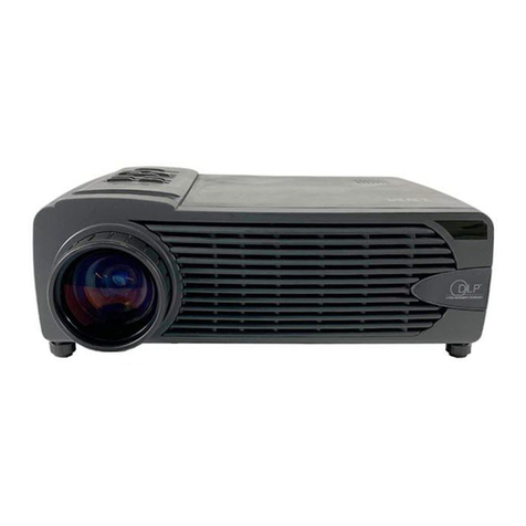
DHS Systems SXGA+ User manual

TECHNICAL MANUAL
OPERATOR AND FIELD MAINTENANCE MANUAL
FOR
MEDIUM SXGA+ PROJECTION SYSTEM
SYSTEM PART NUMBER BP300A019
MEDIUM SXGA+ PROJECTION SYSTEM w/MX PLENUM & ENVIRONMENTAL KIT
SYSTEM PART NUMBER 1003080
33 Kings Highway, Orangeburg, NY 10962 Phone: 845-359-6066
Fax: 256-774-1567
Hotline: 800-977-3647
TECH MANUAL PART NUMBER: 1006380 Web: www.drash.com
ISO 9001: 2000 Registered
Quality Management System


Operation & Maintenance Medium SXGA+ Projection System
Part Number 1006380 a DHS Systems LLC
This document contains information proprietary to DHS Systems LLC and is intended solely for use by its customers. No portion of this document may be reproduced
for release to a third party without written consent of DHS Systems LLC.
SAFETY STEPS TO FOLLOW IF SOMEONE IS
THE VICTIM OF ELECTRICAL SHOCK.
SEND FOR HELP AS SOON AS POSSIBLE.
DO NOT TRY TO PULL OR GRAB THE INDIVIDUAL.
IF POSSIBLE, TURN OFF THE ELECTRICAL POWER.
IF YOU CANNOT TURN OFF THE ELECTRICAL POWER, PULL, PUSH OR
LIFT THE PERSON TO SAFETY USING A DRY WOODEN POLE, OR A
DRY ROPE, OR SOME OTHER INSULATING MATERIAL.
AFTER THE INJURED PERSON IS FREE OF CONTACT WITH THE
SOURCE OF ELECTRICAL SHOCK, MOVE THE PERSON A SHORT
DISTANCE AWAY AND IMMEDIATELY START ARTIFICIAL
RESUSCITATION.

Operation & Maintenance Medium SXGA+ Projection System
Part Number 1006380 b DHS Systems LLC
This document contains information proprietary to DHS Systems LLC and is intended solely for use by its customers. No portion of this document may be reproduced
for release to a third party without written consent of DHS Systems LLC.
WARNING
HIGH VOLTAGE
is used in operation of this equipment.
DEATH ON CONTACT
may result if personnel fail to observe safety precautions.
Never work on electronic equipment unless there is another person nearby who is familiar with operation and hazards
of the equipment and who is competent in administering first aid. When operators aid the technician, the technician
must warn operators about dangerous areas.
When possible, shut off power supply to equipment before beginning work on equipment. Take particular care to
ground every capacitor that could potentially store a dangerous electrical charge. Turn off power when working inside
equipment. Always ground every part of equipment before touching it.
Be careful to not contact high-voltage connections or 115 VAC input connections when installing or operating
equipment.
Whenever the nature of operation permits, keep one hand away from equipment to reduce hazard of current flowing
through the body.
WARNING: Do not be misled by the term “low voltage.” Under adverse conditions, potentials as low as 50 volts may
cause death.
For Artificial Respiration, refer to FM 4-25.11.

Operation & Maintenance Medium SXGA+ Projection System
Part Number 1006380 c DHS Systems LLC
This document contains information proprietary to DHS Systems LLC and is intended solely for use by its customers. No portion of this document may be reproduced
for release to a third party without written consent of DHS Systems LLC.
ELECTRICAL HAZARD
Under adverse conditions, voltage used in this equipment can cause death or serious injury. Observe the following
safety precautions:
GROUND THE EQUIPMENT Before connecting primary power cables; connect grounding cable from
ground lug on power control box to earth ground. Do not remove grounding
cable until signal cables and primary power cables have been disconnected
and generator has been shut down.
AVOID THE POWER INPUT Be careful not to contact 115 VAC input connections when installing or
servicing equipment.
DO NOT SERVICE ALONE Never work on equipment unless there is another person nearby who is
familiar with operation and hazards of equipment and who can administer
first aid.
USE ONLY ONE HAND Whenever possible, use only one hand to service equipment. Keep other
hand away to reduce hazard of current flowing through vital organs of the
body.
WARNING
BURN HAZARD
Equipment may be hot to touch. Allow unit to cool before handling or use gloves when handling.
Failure to observe this warning can result in serious injury.

Operation & Maintenance Medium SXGA+ Projection System
Part Number 1006380 d DHS Systems LLC
This document contains information proprietary to DHS Systems LLC and is intended solely for use by its customers. No portion of this document may be reproduced
for release to a third party without written consent of DHS Systems LLC.
WARNING
HEAVY EQUIPMENT
Improperly lifting or carrying heavy equipment can result in serious injury or death. Refer to the
following weight limits as guidelines:
Handling Function One-Person
Max. Lift Two-Person
Max. Lift Two-Person Max.
Lift (Male Only)
Lift object from floor and place it on surface not
greater than 5 feet above floor. 37 lb. 74 lb. 112 lb.
Lift object from floor and place it on surface not
greater than 3 feet above floor. 44 lb. 88 lb. 174 lb.
Carry object 33 feet or less. 42 lb. 84 lb. 164 lb.

Operation & Maintenance Medium SXGA+ Projection System
Part Number 1006380 e DHS Systems LLC
This document contains information proprietary to DHS Systems LLC and is intended solely for use by its customers. No portion of this document may be reproduced
for release to a third party without written consent of DHS Systems LLC.
ESD
CLASS 1
GENERAL HANDLING PROCEDURES FOR ESD ITEMS
•USE WRIST GROUND STRAPS OR
MANUAL GROUNDING PROCEDURES.
•
PERIODICALLY CHECK CONTINUITY
AND RESISTANCE OF GROUNDING
SYSTEM.
•
KEEP ESD ITEMS IN PROTECTIVE
COVERING WHEN NOT IN USE. •
USE ONLY METALIZED SOLDER
SUCKERS.
•
GROUND ALL ELECTRICAL TOOLS
AND TEST EQUIPMENT. •
HANDLE ESD ITEMS IN PROTECTED
AREAS ONLY.
MANUAL GROUNDING PROCEDURES
•MAKE CERTAIN EQUIPMENT IS
POWERED DOWN.
•
TOUCH PACKAGE OR
REPLACEMENT ESD ITEM TO
GROUND BEFORE OPENING.
•TOUCH GROUND PRIOR TO
REMOVING ESD ITEMS.
•
TOUCH GROUND PRIOR TO
INSERTING REPLACEMENT ESD
ITEMS.
ESD PROTECTIVE PACKAGING AND LABELING
•COVER ANTISTATIC MATERIAL WITH AN OUTER WRAP OF EITHER TYPE 1
ALUMINIZED MATERIAL OR CONDUCTIVE PLASTIC FILM OR HYBRID LAMINATED BAGS
HAVING AN INTERIOR OF ANTISTATIC MATERIAL WITH AN OUTER METALIZED LAYER.
•LABEL WITH SENSITIVE ELECTRONIC SYMBOL AND CAUTION NOTE.

Operation & Maintenance Medium SXGA+ Projection System
Part Number 1006380 f DHS Systems LLC
This document contains information proprietary to DHS Systems LLC and is intended solely for use by its customers. No portion of this document may be reproduced
for release to a third party without written consent of DHS Systems LLC.
WARNING
HIGH VOLTAGE is produced when this unit is in operation. Death or severe burns may result if personnel fail
to observe safety precautions.
WARNING
To avoid possible electrical shock, do not remove grounding cable until signal cables and primary power
cables have been disconnected.
WARNING
Remove all rings, watches, and other jewelry when performing maintenance on this equipment. Secure all
loose fitting clothing to prevent from being caught in moving or rotating parts. Death or loss of limb may
result.
WARNING
Do not attempt to service or otherwise make any adjustments, connections or reconnection of wires or cables
until J series Front/Rear Projection System is shut down and completely de-energized. Death or severe
burns may result.
WARNING
Trichlorotrifluoroethane, trichloroethane, and similar chemical solvents threaten public health and the
environment by destroying ozone in earth’s upper atmosphere. Use only nonhazardous cleaning material
such as a white clean cloth, water, and mild detergent.
WARNING
The screen surface must be stored in its pouch when not in use to prevent damage and discoloration.
While in storage, avoid extreme temperature conditions. If surface becomes sticky, see cleaning
instructions (WP 0016). If stored at temperatures far below room temperatures, allow the screen to
warm up to room temperature before unfolding. This will ensure the film is being handled in its most
flexible state and will prevent surface cracks.

Operation & Maintenance Medium SXGA+ Projection System
Part Number 1006380 i DHS Systems LLC
This document contains information proprietary to DHS Systems LLC and is intended solely for use by its customers. No portion of this document may be reproduced
for release to a third party without written consent of DHS Systems LLC.
TECHNICAL MANUAL
OPERATOR AND UNIT SUPPORT MAINTENANCE MANUAL
FOR
DC2E
MEDIUM SXGA+ PROJECTION SYSTEM
TABLE OF CONTENTS WP Sequence No.
WARNING SUMMARY
HOW TO USE THIS MANUAL
CHAPTER 1 – GENERAL INFORMATION, EQUIPMENT DESCRIPTION, AND
THEORY OF OPERATION
General Information....................................................................................................................... 0001
Equipment Description and Data ................................................................................................... 0002
Theory of Operation ...................................................................................................................... 0003
CHAPTER 2 – OPERATOR INSTRUCTIONS
Description and Use of Controls, Indicators, and Connections ....................................................... 0004
Medium SXGA+ Projection System Setup/Takedown Procedures.................................................. 0005
Medium SXGA+ Multiple Screens Setup/Takedown Procedures.................................................... 0006
Projector & Screen Adjustment Procedures................................................................................... 0007
Projector Software Procedures...................................................................................................... 0008
Equipment Storage Plan................................................................................................................ 0009
CHAPTER 3 – OPERATOR TROUBLESHOOTING
Operator Troubleshooting Index .................................................................................................... 0010
Operator Troubleshooting, Mechanical .......................................................................................... 0011
Operator Troubleshooting, Video & Power..................................................................................... 0012
CHAPTER 4 – OPERATOR MAINTENANCE INSTRUCTIONS
Service upon Receipt .................................................................................................................... 0013
PMCS Introduction ........................................................................................................................ 0014
PMCS ........................................................................................................................................... 0015
Equipment Maintenance Procedures............................................................................................. 0016
CHAPTER 5 – DESTRUCTION OF EQUIPMENT
Destruction of Equipment ………................................................................................................... 0017
Destruction Procedures ……......................................................................................................... 0018
CHAPTER 6 – SUPPORT INFORMATION
Components of End Item............................................................................................................... 0019

Operation & Maintenance Medium SXGA+ Projection System
Part Number 1006380 ii DHS Systems LLC
This document contains information proprietary to DHS Systems LLC and is intended solely for use by its customers. No portion of this document may be reproduced
for release to a third party without written consent of DHS Systems LLC.
HOW TO USE THIS MANUAL
PURPOSE AND SCOPE
This technical manual provides Operator and Unit level maintenance information for the Medium SXGA+ Projection
System. The information includes equipment description and theory of operation, operator instructions,
troubleshooting procedures, maintenance and testing procedures, and supporting data.
ARRANGEMENT, IDENTIFICATION AND LOCATION OF FRONT MATTER, REAR MATTER, CHAPTERS, AND
WORK PACKAGES
This manual is composed of front matter, chapters containing Work Packages (WPs), appendixes, and rear matter.
These areas are described in greater detail in the following paragraphs.
Front Matter
The front matter includes such items as the Warning Summary, List of Effective Pages/WPs, Table of Contents, and
How to Use This Manual.
Chapters and WPs
The WPs contain information pertinent to the performance of specific tasks. Each WP is maintained as a separate
entity. The WPs are grouped into chapters based on overall content. WPs are arranged in numerical sequence
regardless of chapter division. The chapter divisions and the WPs contained within the chapters are listed in the
Table of Contents. The contents of each chapter are outlined briefly in the following paragraphs.
Chapter 1 - General Information, Equipment Descriptions, and Theory of Operation. This chapter provides general
and descriptive information concerning the equipment. Theory of Operation appropriate to the maintenance level
covered is also provided.
Chapter 2 - Operator Instructions. This chapter provides a description and location of the controls, indicators, and
connectors on each piece of equipment used in the Medium SXGA+ Projection System. It also contains a description
and location of the decals and data plates for each piece of equipment and operation under usual and unusual
conditions.
Chapter 3 - Operator Troubleshooting Procedures. This chapter provides operational checkout and troubleshooting
procedures appropriate to the maintenance level covered.
Chapter 4 – Operator Maintenance Procedures. This chapter provides troubleshooting/fault isolation procedures
appropriate to the maintenance level covered.
Chapter 5 – Destruction of Equipment. This chapter provides procedures for Destruction of Equipment.
Chapter 6 – Supporting Information. Included is a list of reference material, the Components of End Item (COEI) list.

Operation & Maintenance Medium SXGA+ Projection System
Part Number 1006380 iii DHS Systems LLC
This document contains information proprietary to DHS Systems LLC and is intended solely for use by its customers. No portion of this document may be reproduced
for release to a third party without written consent of DHS Systems LLC.
Identifying WPs
Each WP is identified by a six-digit number. The first four digits are assigned sequentially. The last two digits, if other
than 00 (01, 02, 03, etc.), indicate WP revision level. WPs are revised due to equipment configuration differences,
support equipment differences, or other similar situations. For example:
•WP 0005 00 might cover installation of a cable on a basic unit.
•WP 0005 01 might cover installation of the same cable on a differently configured unit.
•Installation of an alternate handle in place of the original handle, requiring a different procedure.
•Installation of the handle using an alternate technique or different tools.
•Installation of the handle using alternate fasteners.
Locating WPs
There are two ways to locate a WP when the number is not known, using the Table of Contents in the manual's front
matter and using the Index in the manual's rear matter.
Locating a WP in the Table of Contents
First determine the category of the WP subject and then find the appropriate chapter in the Table of Contents. Scan
the WP titles in that chapter until the WP subject matter is found. In the example below, it is desired to locate the
PMCS for the Operator (shaded). PMCS falls into the category of maintenance. Go to the Table of Contents and find
the chapter titled "Operator Maintenance Instructions." (Make sure the chapter applies to the appropriate
maintenance level). Scan the WP titles within that chapter until "PMCS" is found, and follow the leader line to find the
WP number.
TABLE OF CONTENTS
WP Sequence No.
WARNING SUMMARY
HOW TO USE THIS MANUAL
CHAPTER 1 - GENERAL INFORMATION, EQUIPMENT DESCRIPTION, AND THEORY OF OPERATION
General Information.....................................................................................................WP 0001
Equipment Data and Description................................................................................WP 0002
Theory of Operation.....................................................................................................WP 0003
CHAPTER 2 - OPERATOR INSTRUCTIONS
Description and Use of Operator Controls, Indicators and Connections...................WP 0004
Medium SXGA+ Projection System Setup/Takedown Procedures...........................WP 0005
Medium SXGA+ Multiple Screens Setup/Takedown Procedures .............................WP 0006
Projector & Screen Adjustment Procedures……. ......................................................WP 0007

Operation & Maintenance Medium SXGA+ Projection System
Part Number 1006380 iv DHS Systems LLC
This document contains information proprietary to DHS Systems LLC and is intended solely for use by its customers. No portion of this document may be reproduced
for release to a third party without written consent of DHS Systems LLC.
WP CONTENT AND PRESENTATION
The content and the presentation techniques used in the WPs vary according to the material covered.
Common Features
In all cases, the WP title is placed at the top of the page immediately below the manual and WP number and is set off
by horizontal lines as shown below.
Medium SXGA+ Projection System 0002
GENERAL INFORMATION, EQUIPMENT DESCRIPTION, AND THEORY OF OPERATION
MEDIUM SXGA+ PROJECTION SYSTEM
EQUIPMENT DATA AND DESCRIPTION
On the second and subsequent pages of the WP, the manual and WP number is repeated.
The page number is placed at the bottom of the page and consists of the WP number and a sequential number
denoting the page within the WP as shown below.
0002-1
Paragraphs are not numbered.
Primary paragraphs are denoted by headings set in BOLD UPPER CASE (CAPITAL) type.
Secondary and lower-level paragraphs are denoted by headings set in Bold Upper and Lower Case type. These
paragraphs always relate to and are subordinate to the most recent primary paragraph heading.
Figures and tables are numbered sequentially within each WP starting with numeral 1

Operation & Maintenance Medium SXGA+ Projection System
Part Number 1006380 DHS Systems LLC
CHAPTER 1
OPERATOR INSTRUCTIONS
FOR
DC2E
MEDIUM SXGA+ PROJECTION SYSTEM


Operation & Maintenance Medium SXGA+ Projection System 0001
Part Number 1006380 0001-1 DHS Systems LLC
This document contains information proprietary to DHS Systems LLC and is intended solely for use by its customers. No portion of this document may be reproduced
for release to a third party without written consent of DHS Systems LLC.
GENERAL INFORMATION, EQUIPMENT DESCRIPTION, AND THEORY OF OPERATION
MEDIUM SXGA+ PROJECTION SYSTEM
GENERAL INFORMATION
SCOPE
This Operators’ and Maintenance Manual provides general information, instructions and procedures for setup,
operation, teardown, maintenance, and repair of the Medium SXGA+ Projection System components.
Configuration of the Medium SXGA+ Projection System is shown in Figure 1.
Figure 1. Medium SXGA+ Projection System Configuration.

Operation & Maintenance Medium SXGA+ Projection System 0001
Part Number 1006380 0001-2 DHS Systems LLC
This document contains information proprietary to DHS Systems LLC and is intended solely for use by its customers. No portion of this document may be reproduced
for release to a third party without written consent of DHS Systems LLC.
CONSOLIDATED INDEX OF ARMY PUBLICATIONS AND BLANK FORMS
Refer to the latest issue of DA PAM 25-30 to determine whether there are new editions, changes, or additional
publications pertaining to the equipment.
MAINTENANCE FORMS, RECORDS, AND REPORTS
1. Reports of Maintenance and unsatisfactory Equipment. DA PAM 750-8. The Army Maintenance Management
System (TAMMS) Users Manual, prescribes the DA forms and procedures used for equipment maintenance. Air
Force personnel use AFR 66-1 for reporting maintenance and TO-00-35D54 for reporting unsatisfactory equipment.
Navy personnel report maintenance performed utilizing the Maintenance Data Collection Subsystem (MDCS) in
accordance with OPNAVINST 4790.2, Volume 3 and unsatisfactory material/conditions in accordance with
OPNAVINST 4790.2, Volume 2, chapter 17. Marine Corps maintains forms and procedures as prescribed by TM
4700-15/1
2. Reporting of Item and Packaging Discrepancies. Fill out and forward SF 364, Supply Discrepancy Report (SDR)as
prescribed in AR 735-11-2/DLAR 4140.55/SECNABINST 4355.18/AFR 400-54/MCO 4430.3J.
3. Reporting Transportation Discrepancies. Fill out and forward SF 361, Transportation Discrepancy Report (TDR),
as prescribed in AR 55-38/NAVSUPINST 6410.33C/AFR 75-18/MCO P4610.19D/DLAR 4500.15.
REPORTING EQUIPMENT IMPROVEMENT RECOMMENDATIONS (EIR)
If the equipment needs improvement, let us know. Submit an EIR. You, the user, are the only one who can tell us
what you don’t like about your equipment. Let us know why you don’t like the design or performance. Put it on an SF
368, Product Quality Deficiency Report (PQDR). Mail it to: Technical Publications, DHS Systems, 33 Kings Highway,
Orangeburg, New York 10962-1802. We’ll send you a reply.
CORROSION PREVENTION AND CONTROL (CPC)
Corrosion Prevention and Control (CPC) of Army material is a continuing concern. It is important that any corrosion
problems with the Large Screen Front Projection System be reported so that the problem can be corrected and
improvements can be made to prevent future problems.
While corrosion is typically associated with rusting of metal, it can also include deterioration of other types of
materials, such as rubber and plastic. Unusual cracking, softening, swelling, or breaking of these materials may be
considered a corrosion problem.
If a corrosion problem is identified, it shall be reported using SF 368, PQDR. Use of key words such as “corrosion,”
“rust,” “deterioration,” or “cracking” ensures the information is identified as a CPC problem.
The form should be submitted to: Technical Publications, DHS Systems, 33 Kings Highway, Orangeburg, New York
10962-1802. We’ll send you a reply.
OZONE DEPLETING SUBSTANCES (ODS)
In accordance with Executive Order 12856, other public laws, DoD policy, and Army policy, the use of ODS has been
banned for all new acquisitions. Operation and maintenance of the AVCS do not require the use of ODS.
DESTRUCTION OF ARMY MATERIAL TO PREVENT ENEMY USE
Procedures to destroy this equipment to prevent enemy use are in accordance with TM 750-244-2, Procedures for
Destruction of Electronic Material to Prevent Enemy Use.

Operation & Maintenance Medium SXGA+ Projection System 0001
Part Number 1006380 0001-3 DHS Systems LLC
This document contains information proprietary to DHS Systems LLC and is intended solely for use by its customers. No portion of this document may be reproduced
for release to a third party without written consent of DHS Systems LLC.
PREPARATION FOR STORAGE OR SHIPMENT
Place items in administrative storage for short periods of time when a shortage of maintenance resources exist. It
should be possible to place items in a state of mission readiness either within 24 hours or within the time frame that
the directing authority may determine. Keep appropriate maintenance records during storage.
Prior to placing the equipment in administrative storage, Army activities perform Preventative Maintenance Checks
and Services (PMCS), complete Equipment Serviceability Criteria (ESC) evaluations, correct shortcomings and
deficiencies, and complete all Modification Work Orders (MWO). When removing Items from administrative storage,
the operator performs PMCS to ensure operational readiness.
Inside storage is preferred for items selected for administrative storage. If inside storage is not available, use trucks,
vans, or other containers
WARRANTY INFORMATION
The Medium SXGA+ Projection System has a limited 1 year warranty, with the following exceptions
•Deployable Command & Control Equipment Cables: 30 days
•Deployable Command & Control Equipment Lamps and Bulbs: 500 Hours/ 90 Days
•Deployable Command & Control Equipment Touch Panels: 90 Days
The warranty starts on the date found in block 23 of DA Form 2408-9, Equipment Control Record. If no DA 2408-9 is
available, the date will be the recorded date of shipment of the equipment from the factory. Report all defects to the
supervisor, who will take appropriate action. Contact the Regional Support Center (RSC) representative for further
information on Warranty items.
NOMENCLATURE CROSS-REFERENCE LIST
Common names and/or abbreviations are used in the manual to make a procedure easier to read. Table 1 matches
the official nomenclatures with the common names or abbreviations.
Table 1. Nomenclature Cross-Reference List.
OFFICIAL NOMENCLATURE
COMMON NAME or ABBREVIATIONS
Audio Visual Switching System
AVSS
Bayonet Neill-Concelman (Connector)
BNC (Connector)
Certified Technology Specialist
CTS
Certified Technology Specialist-Design
CTS-D
Certified Technology Specialist-Installation
CTS-I
Composite Video
CV
D-Subminiature 9-pin (Connector)
DB9 (Connector)
Data Circuit Terminating Equipment
DCE
Deployable Command & Control Equipment
DC2E
Dynamic Host Configuration Protocol
DHCP
Digital Light Processing
DLP
Electromagnetic Interface
EMI
Electrostatic Discharge
ESD
Front Projection Mode
FPM
High-Bandwidth digital Content Protection
HDCP
High-Definition Multimedia Interface (Connector)
HDMI (Connector)
HD15 (Connector)
High Density 15-pin (Connector)

Operation & Maintenance Medium SXGA+ Projection System 0001
Part Number 1006380 0001-4 DHS Systems LLC
This document contains information proprietary to DHS Systems LLC and is intended solely for use by its customers. No portion of this document may be reproduced
for release to a third party without written consent of DHS Systems LLC.
Table 1. Nomenclature Cross-Reference List (Cont).
OFFICIAL NOMENCLATURE
COMMON NAME or ABBREVIATIONS
High-Definition Serial Digital Interface
HD-SDI
Internet Protocol
IP
J Series Front/Rear projection System
JSFRPS
Local Area Network
LAN
Medium Audio-Visual Switching System
AVSS-MED
Plain Old Telephone Service
POTS
Rear Projection Mode
RPM
Red, Green, Blue Sync
RGBS
Red, Green, Blue, Horizontal, Vertical
RGBHV
Red, sync on Green, Blue
RGsB
Radio Frequency Interface
RFI
Radio Corporation of America (Connector)
RCA (Connector)
Recommended Standard 232
RS232
Standard Definition
SD
Small Audio-Visual Switching System
AVSS-SMALL
Super Video Graphics Array
SVGA
Super Extended Graphics Array
SXGA
Transmission Control Protocol/Interface Protocol
TCP/IP
Video Graphics Array
VGA
COMMON VIDEO SIGNALS
Computer: The most common computer video resolutions today are 640 x 480 thru 1920 x 1200. The signal consists
of red, green, blue, horizontal sync and vertical sync (RGBHV).
Composite: Composite video is the video format of an analog television signal before it is combined with sound and
modulated onto an RF carrier. Composite video is the combination of luminance and chrominance on a single cable.
This is typically the signal type you get from a camera or the “video out” on the back of a VCR or DVD. The most
common formats used around the world are NTSC, PAL, or SECAM. NTSC is the US standard.
S-Video: S-Video means “Separate Video”. It is also called Y/C video. Y/C video is an analog signal that carries the
video data (luminance and chrominance) as two separate signals.
COMMON VIDEO CONNECTORS
HD15: The common 15-pin VGA connector found on most video cards, computer monitors and other devices is
almost universally called “HD-15”. HD stands for “high-density”, which distinguishes it from connectors having the
same form factor but only two rows of pins. The HD connector has three rows of five pins.
BNC: The BNC connector is a type of RF connector used for terminating coaxial cable and is commonly used for
video connections of both analog and SDI video type interfaces.
RCA: The RCA jack is a commonly used connector in audio/visual and can be used for both composite video and line
level audio.
DB13W3: The DB13W3 is an analog video interface connector and can be converted into standard VGA connector
using cables and adapters that are commonly available.
RJ-45: The RJ-45 is an eight-wire connector used commonly to connect computers onto a local-area networks (LAN)
especially Ethernets.

Operation & Maintenance Medium SXGA+ Projection System 0001
Part Number 1006380 0001-5 DHS Systems LLC
This document contains information proprietary to DHS Systems LLC and is intended solely for use by its customers. No portion of this document may be reproduced
for release to a third party without written consent of DHS Systems LLC.
COMMON AUDIO SIGNALS
Microphone Level: Microphone (MIC) level is a nominal signal coming directly from a microphone. Very low, in the
microvolt’s, and requires a preamp with at least 60 dB gain before using with any line-level equipment
Line Level: Line level is a term used to denote the strength of an audio signal used to transmit analog sound
information between audio components such as CD and DVD players. Line level is a standard +4 dBu or -10dBV
audio level.
Balanced Audio: A balanced audio signal requires two signal wires and one ground/shield wire. The two signal wires
are of inverted polarity to each other. The two inverted signals along with an overall shield rejects outside noise over
long cable distances.
Unbalanced Audio: An unbalanced audio signal requires two wires, one wire is for the +signal and the other wire is
for ground or return. Unbalanced audio works fine for short distances, but is not recommended for long distances
because it is more susceptible to outside noise interferences.
Mono Audio: Mono (Monaural) is a signal channel of sound. Mono is typically relating to a system of transmitting,
recording, or reproducing sound in which one or more sources are connected to a signal channel.
Stereo Audio: Stereo (Stereophonic) sound is the reproduction of sound using two or more independent audio
channels through a symmetrical configuration of loudspeakers in such a way as to create a natural impression of
sound.
COMMON AUDIO CONNECTORS
XLR: The XLR connector is a rugged electrical connector design and the most common XLR is the 3-pin, used mostly
for microphones and other balanced audio connections.
RCA Connector: The RCA jack is a commonly used connector in audio/visual and can be used for both line level
audio and composite video.
1/8” TRS: TRS stands for Tip, Ring & Sleeve and is used to pass stereo audios three signals (left, right and ground)
from a speaker connection to a sound card on a PC.
¼” TRS: Is the original “jack-like plug” and is the same as the 1/8” TRS, except for size.
VIDEO DISTRIBUTION METHODS
HD15: HD15 cables are the most common way of sending computer video from a computer to monitors or display
types.
CAT5: CAT5 or UTP is a typical 8-wire cable is another popular method for sending computer video over long
distances.
Wireless: The wireless transmission of computer video signals is often a packet loss problem as well as the security
concerns attached. Also, band-width limitations reduce the resolutions and frames per second transmitted. Wireless
is not recommended for full motion high resolution video.

Operation & Maintenance Medium SXGA+ Projection System 0001
Part Number 1006380 0001-6 DHS Systems LLC
This document contains information proprietary to DHS Systems LLC and is intended solely for use by its customers. No portion of this document may be reproduced
for release to a third party without written consent of DHS Systems LLC.
LIST OF ABBREVIATIONS/ACRONYMS
Abbreviation/Acronym Name
AC Alternating Current
AVSS Audio Visual Switching System
BII Basic Issue Items
BTU British Thermal Unit
CAGEC Commercial and Government Entity Code
CB Circuit Breaker
CCS Command Center System
COEI Components of End Item
COP Common Operational Picture
COTS Commercial off The Shelf
CP Command Post
CPC Corrosion Prevention and Control
D Depot
DC2E Digital Command and Control Equipment
DMR Depot Mobilization Requirements
DS Direct Support
EIR Equipment Improvement Recommendations
ESC Equipment Serviceability Criteria
FGC Functional Group Code
FM Field Manual
FO Foldouts
GS General Support
HDBK Handbook
HMMWV High Mobility Multi-Purpose Wheeled Vehicle
HVAC Heating, Ventilating and Air Conditioning
I/O Input/Output
LED Light Emitting Diode
MAC Maintenance Allocation Chart
MOS Military Occupational Specialties
MWO Modification Work Order
NSN National Stock Number
PDP Power Distribution Panel
PMCS Preventive Maintenance Checks and Services
PQDR Product Quality Deficiency Report
PSI Pounds per Square Inch
P/N Part Number
QA Quality Assurance
RPSTL Repair Parts and Special Tools List
SDR Supply Discrepancy Report
SIMPL Symbol Intensive Master Programming Language
SMR Source, Maintenance and Recoverability
SOP Standing Operating Procedure
TAMMS Army Maintenance Management System
TB Troubleshooting
TDR Transportation Discrepancy Report
TMDE Test, Measurement, and Diagnostic Equipment
TMSS Trailer Mounted Support System
U/I Unit of Issue
UPS Uninterruptible Power Supply
VAC Voltage, Alternating Current
WP Work Package
This manual suits for next models
2
Table of contents
Other DHS Systems Projector manuals

