manuals.online logo
Brands
  1. Home
  2. •
  3. Brands
  4. •
  5. Diablo Controls
  6. •
  7. Security Sensor
  8. •
  9. Diablo Controls DSP-40S User manual

Diablo Controls DSP-40S User manual

Page 1 of 2
Product Profile
DSP-40S Vehicle Detector
All this and a 5-Year Warranty too!
Features
Works on any in-ground
inductive loop from 20 to
2000 microhenries.
Designed to be cross talk
free between other loops
Automatically compensates
for loop and lead-In sizes
Separate Power/Fail and
Detect LED's for both
channels
Small profile, perfect for
many installations
Fail safe operation
Wide low-voltage operation
This series of Diablo
Controls detectors are
covered by United States
Patent number US
7,132,959 “Non-Interfering
Vehicle Detection.”
Separate Power/Fail and
Detect LEDs.
Overview
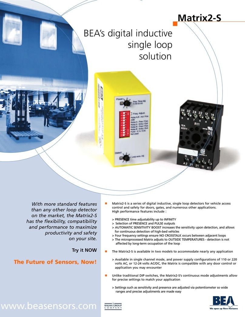
At last a plug-in detector that will operate on any voltage from 10
to 30 volts AC or DC. The DSP-40S detector is covered by United
States patent number US 7,132,959 “Non-Interfering Vehicle
Detection.” This detector is virtually cross-talk free in most
applications. It has been specifically designed to handle parking,
drive-through and access control applications where solid-state
outputs are required for both the detect and fail outputs. The
sensitivity level may be changed. (See below). The detector loop
inductance should be between 20 and 2000 microhenries.
LED Indicators
The green Power LED will be on steady to indicate the detector is
operating and powered. The red Detect LED will turn on when a
vehicle is over the loop detection area.
Detect Memory
Power interruptions of short duration are ignored. If power fails for
approximately 1 ½ seconds or less the detector “remembers” a
vehicle.
Sensitivity and Reset Push Button
The Reset/Sens. button is used for two functions. A short press
and release of the button will reset the detector and the LED's will
both flash from 1 to 4 times, indicating the detector's sensitivity
level. The detector is shipped from the factory with the sensitivity
set at level 3.
If a different sensitivity level is required:
Push and continue to hold the button until the LED's start flashing
- release the button immediately after the desired number of
flashes. For example, if the sensitivity is to be changed to level 2,
push and hold the button until the LED's flash twice then
immediately release the button. The sensitivity level can always
be verified by a quick tap on the push button. This will reset the
detector and flash the two LED's indicating the present level.
Level 1 - Very Low
Level 2 - Low
Level 3 - Normal (Factory setting)
Level 4 - High
Loop or Wire Failures
In the case of a loop circuit failure, the green LED flashes slowly
(twice per second) for an open loop circuit failure. The green LED
will flash fast (10 times per second) to indicate a shorted loop
circuit.
Page 2 of 2
Visit our Website at www.diablocontrols.com for the most current information on all of our products.
Specifications are subject to change.
DSP-40_CUT_A 2/5/2014
Product Profile
DSP-40S Vehicle Detector
Fail Safe vs Fail Secure
A fail safe detector will output “detect” when the loop circuit is failed. This is always useful on a
safety loop. On the free exit loop this will keep the gate open until the situation is fixed. This is
useful in applications where it is important to allow traffic flow to continue. A fail secure detector will
never output “detect” when the loop circuit is failed. This will keep the gate closed. This is useful in
high-security areas or installations where containment is needed. The DSP-11 is a fail safe
detector. Note: Never use a fail secure detector on a safety loop.
Outputs
Solid-state (open transistor collectors) for both detect” and fail outputs. 30 mA maximum current
sink - transient voltage protected.
Power
12 to 30 volts DC
Operating Temperature
-35°F to 165°F (-37°C to 74°C)
Size
Height: 2.4" Width: 0.8" Depth: 2.25”
Connector
10-position Molex Type 09-48-1104
Mates with many female PCB 0.156” pitch headers in use by some access control devices and gate
operators.
1 - Loop input
2 - Loop input
3 - Power* (10 to 30 volts AC or DC)
4 - No Connection
5 - No Connection
6 - Fail output -connects to common for fail.
7 - Fail output -connects to common for fail.
8 - Detect output -connects to common for detect.
9 - Power* (10 to 30 volts AC or DC)
10 - Power Common
*Either or both of these pins can be used to supply power to the detector.
Ordering Information
Only one model available: DSP-40S
Veteran Owned & Operated
Diablo Controls, Inc.
565 Dakota St, Unit F
Crystal Lake, IL 60012
Toll Free 866-395-6677
www.diablocontrols.com
[email protected]

Other Diablo Controls Security Sensor manuals

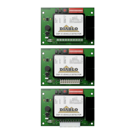
Diablo Controls DSP-15 User manual

Diablo Controls

Diablo Controls DSP-15 User manual

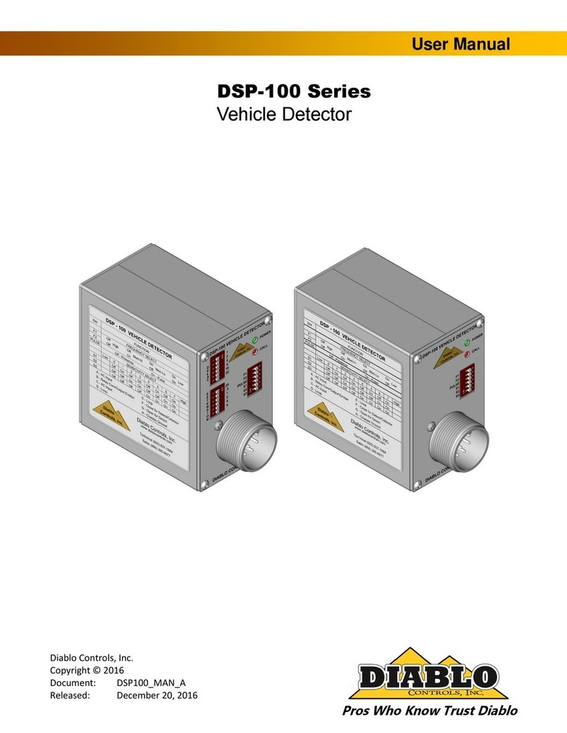
Diablo Controls DSP-100 Series User manual

Diablo Controls

Diablo Controls DSP-100 Series User manual

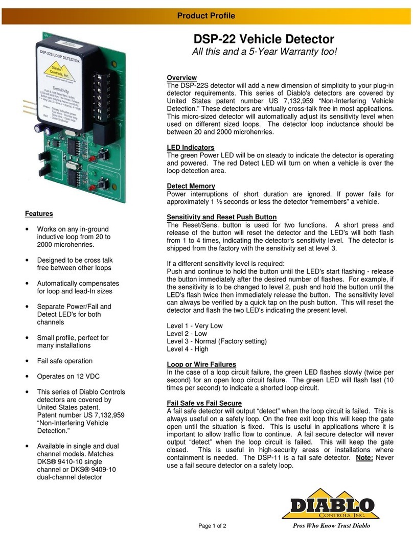
Diablo Controls DSP-22 User manual

Diablo Controls

Diablo Controls DSP-22 User manual

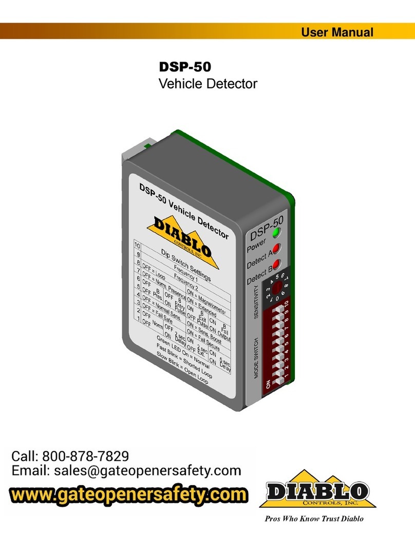
Diablo Controls DSP-50 User manual

Diablo Controls

Diablo Controls DSP-50 User manual

Popular Security Sensor manuals by other brands

ESYLUX PD-C360i/24 DIMplus manual

ESYLUX

ESYLUX PD-C360i/24 DIMplus manual

Meiji MSD-02 instruction manual

Meiji

Meiji MSD-02 instruction manual

GDS M1 quick start guide

GDS

GDS M1 quick start guide

Telefire TFB-180SA Technical instructions

Telefire

Telefire TFB-180SA Technical instructions

Alarmtech AD 800-AM Instruction and installation manual

Alarmtech

Alarmtech AD 800-AM Instruction and installation manual

Waters ACQUITY QDa Overview and maintenance guide

Waters

Waters ACQUITY QDa Overview and maintenance guide

F&F DRL-60-12 manual

F&F

F&F DRL-60-12 manual

Omron F3SJ-B0185P25-01TS user manual

Omron

Omron F3SJ-B0185P25-01TS user manual

STEINEL PROFESSIONAL US 360 operating instructions

STEINEL PROFESSIONAL

STEINEL PROFESSIONAL US 360 operating instructions

Autronica AutroFlame BG-201 Mounting instructions

Autronica

Autronica AutroFlame BG-201 Mounting instructions

B&D Automatic Technology Wireless WPE-1v1 Wiring and Installation Instructions

B&D

B&D Automatic Technology Wireless WPE-1v1 Wiring and Installation Instructions

Visonic Quatro+ installation instructions

Visonic

Visonic Quatro+ installation instructions

Axis T8341 installation guide

Axis

Axis T8341 installation guide

Inficon Sion operating manual

Inficon

Inficon Sion operating manual

Essence CareHome ES700FL user guide

Essence

Essence CareHome ES700FL user guide

ETC echoflex MOS-IR Series installation guide

ETC

ETC echoflex MOS-IR Series installation guide

System Sensor B114LPBT Installation and maintenance instructions

System Sensor

System Sensor B114LPBT Installation and maintenance instructions

Atim Cloud Wireless ACW/LW8-CTS user guide

Atim Cloud Wireless

Atim Cloud Wireless ACW/LW8-CTS user guide

manuals.online logo
manuals.online logoBrands
  • About & Mission
  • Contact us
  • Privacy Policy
  • Terms and Conditions

Copyright 2025 Manuals.Online. All Rights Reserved.