Diablo 5000B Parts list manual
Diablo 5000B Real-Time Gas Analyzer
Getting Started Manual
Diablo Analytical, Inc.

Diablo 5000B Real Time Gas Analyzer
Getting Started Manual
Copyright 2019, Diablo Analytical, Inc. All rights reserved.
This software and documentation are copyrighted by Diablo Analytical, Inc. All other
brands or product names are trademarks or registered trademarks of their respective
owners.
Diablo Analytical, Inc.
5141 Lone Tree Way
Antioch, CA 94531
Phone: 925-755-1005
Fax: 925-755-1007
E-mail: support@diabloanalytical.com
Home Page: www.diabloanalytical.com
Manual Revision 20190204-1357

DIABLO ANALYTICAL, INC. SOFTWARE LICENSE AGREEMENT AND LIMITED WARRANTY
LICENSE AGREEMENT
IMPORTANT: Please carefully read the License Agreement below before installing the software. The right to
use this software product is sold only on the condition that the customer agrees to the following license.
INSTALLING THE SOFTWARE INDICATES YOUR ACCEPTANCE OF THESE TERMS AND CONDITIONS.
In return for payment of the one-time license fee for this software product, Customer receives from Diablo
Analytical, Inc. (Diablo) a license to use the product subject to the following terms and conditions:
Use: The product may be used one computer or workstation. A separate license agreement and fee is
required for each additional computer or workstation on which the product is used. Customer may not
reverse assemble, decompile, or modify the software.
Copies: The software product may not be duplicated or copied except for archive purposes, program error
verification, or to replace defective media, and all copies made must bear the copyright notices contained in
the original.
Ownership: Purchase of this license does not transfer any right, title or interest in the software product to
Customer except as specifically set forth in this License Agreement. Customer is on notice that the software
product is protected under copyright laws.
Transfer of Rights: This license and the software product may be transferred to a third party, with prior written
consent from Diablo, provided the third party agrees to all the terms of this License Agreement and the
Customer does not retain any copies of the software product.
Sublicensing and Distribution: Customer may not sublicense the software or distribute copies of the software
to the public in physical media or by telecommunication without the prior written consent of Diablo.
Termination: Diablo reserves the right to terminate this license upon breach. In event of termination,
Customer will either return all copies of the product to Diablo, or with Diablo's prior consent, provide Diablo
with a certificate of destruction of all copies.
Updates and Upgrades: Customer agrees that the software does not include updates and upgrades which
may be available from Diablo in a separate support agreement.
Export Restrictions: Customer agrees not to export or re-export the software or any copy in violation of the
U.S. Export Administration regulations or other applicable regulation.
LIMITED WARRANTY
Limited Warranty: Diablo warrants that the original disks are free from defects for 90 days from the date of
delivery of the software.
No Other Warranties: To the maximum extent permitted by applicable law, Diablo expressly disclaims any
warranty for the software product. The software product and any related documentation is provided "as is"
without warranty of any kind, either express or implied, including, without limitation, the implied warranties or
merchantability of fitness for a particular purpose. The entire risk arising out of use or performance of the
software product remains with the customer.
Limitation of Liability and Customer Remedies: Diablo's entire liability and the customer's exclusive remedy
under this license agreement shall be, at Diablo's option, either (a) return of the price paid for the software or
(b) replacement of the software that does not meet Diablo's Limited Warranty and which is returned to Diablo
with a copy of the customer's receipt. Any replacement software will be warranted for the remainder of the

original warranty period, or 30 days, whichever is longer. These remedies are not available outside the
United States of America.
No Liability for Consequential Damages: To the maximum extent permitted by applicable law, in no event
shall Diablo be liable for any damages whatsoever (including, without limitation, damages for loss of business
profit, business interruption, loss of business information, or any other pecuniary loss) arising out of the use or
inability to use the product, even if Diablo has been advised of the possibility of such damages. Because
some states/jurisdictions do not allow the exclusion or limitation of liability for consequential or incidental
damages, the above limitation may not apply to you.

Diablo 5000B Real-Time Gas Analyzer Getting Started Manual v
Contents
Getting Started 1
Overview.......................................................................................................................1
Installation 3
System Installation........................................................................................................3
Support..........................................................................................................................3
MassHunter Acquisition Software.................................................................................3
Verify the MassHunter GC/MS Installation......................................................4
MS Sensor Software.....................................................................................................4
Software Requirements ...................................................................................4
Computer Requirements..................................................................................4
License Activation............................................................................................5
Theory of Operation 7
Sampling Interface........................................................................................................7
Additional Interface Options.............................................................................8
Setting up the Hardware 9
Connecting sample lines...............................................................................................9
Changing Orifice Disks ...............................................................................................10
Temperature controller operation and maintenance...................................................11
Watlow EZ-Zone Controller............................................................................12
Pressure sensor operation and maintenance.............................................................13
To connect the pressure sensor to the cross.................................................13
To connect the pressure sensor controller to the PC ....................................13
To configure the pressure sensor controller: .................................................13
To zero the pressure sensor:.........................................................................14
Special Hardware Considerations...............................................................................15
MSD Configuration for low-mass (hydrogen or helium) detection.................15
Converting the MSD from RTGA to GC/MS ..................................................15
Setting MS Sensor System Options 17
Starting the MS Sensor software................................................................................17
Creating a Method 19
MS Sensor Application Builder ...................................................................................19
Introduction to creating MS Sensor Methods..............................................................19
Method components ...................................................................................................20
Instrument components .................................................................................21
Tuning the RTGA Mass Spectrometer...........................................................22
Add the additional instruments (e.g., the pressure transducer).....................24
Signals components.......................................................................................24

Contents
vi Diablo 5000B Real-Time Gas Analyzer Getting Started Manual
Calculations component (optional) ................................................................26
Data channels component.............................................................................28
Acquisition Settings........................................................................................31
Completing the method..................................................................................32
Acquiring Data 33
Preparation..................................................................................................................33
Start the run ................................................................................................................35
Stop the run and view the results................................................................................35
Troubleshooting 37
Evaluating RTGA Interface Performance ...................................................................37
Addressing Signal Instability.......................................................................................38
Index 41

Diablo 5000B Real-Time Gas Analyzer Getting Started Manual 1
Getting Started
Overview
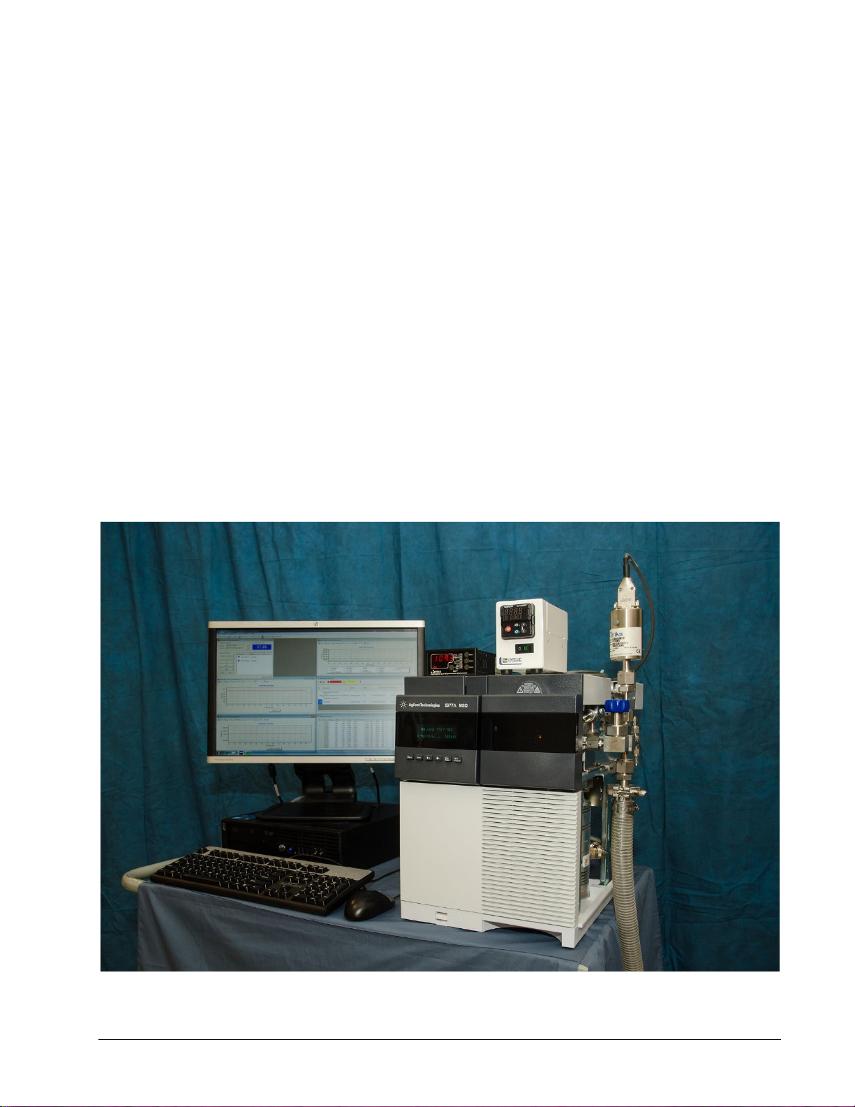
The Diablo Analytical 5000B Real-Time Gas Analyzer (RTGA) monitors gaseous process streams
and produces trend plots and Excel-compatible data files.
The hardware consists of:
•An Agilent Technologies 5977 Mass Selective Detector (MSD), with the Real-Time Gas
Analyzer hardware interface.
•A custom temperature controller with a custom thermal jacket for the interface.
•An MKS PDR2000 Controller with a high-performance capacitance manometer pressure
sensor.
•A vacuum isolation valve.
•Associated tubing and fittings to interface with a customer-supplied sampling system.
•A personal computer (PC).
The analyzer is controlled by the Agilent Technologies MassHunter GC/MS Acquisition software.
Method creation and data processing are done by the Diablo MS Sensor 4.0 software. Both
programs run on a personal computer (PC).


Diablo 5000B Real-Time Gas Analyzer Getting Started Manual 3
Installation
System Installation
Diablo Analytical personnel or an authorized representative will install the 5000B RTGA hardware
and software and will also check out the entire system. The information on this page is provided to
the user for future reference.
Support
Agilent Technologies provides warranty service and support for the 5977 MSD MassHunter GC/MS
computer system. Diablo Analytical provides warranty service and support for the 5000B RTGA
kits. Contact Diablo Analytical if you have any questions about the operation of your RTGA system.
Diablo Analytical, Inc.
5141 Lone Tree Way
Antioch, CA 94531
Phone: (925) 755-1005
Fax: (925) 755-1007
E-mail: support@diabloanalytical.com
Web: http://www.diabloanalytical.com
MassHunter Acquisition Software
See the Agilent Technologies MassHunter GC/MS Acquisition documentation for the installation
procedure. The MassHunter Acquisition software must be correctly installed and configured before
installing and running the MS Sensor software.
NOTE: The MassHunter GC/MS Acquisition software revision must be B.07.05 or later.
Important:
The MassHunter GC/MS Acquisition software must be closed before
starting the MS Sensor Software and attempting to acquire data from the
MSD.

Installation
4 Diablo 5000B Real-Time Gas Analyzer Getting Started Manual
Verify the MassHunter GC/MS Installation
Before attempting to acquire data from a 5977 MSD with the MS Sensor Software, you should verify
that the MassHunter GC/MS data system is configured correctly by performing a standard autotune.
MS Sensor Software
Before installing the Real-Time Gas Analyzer MS Sensor software, read the document “readme.txt”
in the root directory of the MS Sensor distribution USB flash drive. This document contains
installation and usage information that may not be included in the software manual or help file.
The MS Sensor Software Reference Manual is also provided on the USB flash drive. The reference
manual provides more detailed information on how to use the MS Sensor software than is included
in this Getting Started Manual.
To begin installation, run the installation program located in the root directory of the MS Sensor
software distribution USB flash drive. Follow the on-screen instructions.
Software Requirements
The MS Sensor 4.0 software is compatible with Windows 7 SP1, Windows 8/8.1, and Windows 10.
The .NET Framework 4.5.2 must be installed before trying to run MS Sensor 4.0. The .NET
Framework will be installed automatically, if necessary, when you install the software from the
distribution media, or if you use the single-file installer. If you use the web-based installer the .NET
Framework 4.5.2 will be downloaded automatically if necessary. You can also download and install
the .NET Framework 4.5.2 from Microsoft using the following link:
https://www.microsoft.com/en-us/download/details.aspx?id=42642
Note: The .NET Framework 4.5.2 is included with all versions of the Windows 10 operating system.
The MS Sensor software has been designed and tested for use on US/English versions of Microsoft
Windows operating systems.
Agilent 5977 MSD
Currently MS Sensor 4.0 only supports mass spectrometers that are controlled by the Agilent
MassHunter GC/MS data system. Instruments that are controlled by the older MSD ChemStation
software will need to be upgraded to MassHunter before they can be used with MS Sensor 4.0.
IMPORTANT: MS Sensor 4.0 requires MassHunter GC/MS version B.07.05 or later.
Computer Requirements
The MS Sensor software will run on any computer that is compatible with the Agilent MassHunter
GC/MS software.
However, one free RS-232 serial port is required to collect sample pressure data from the pressure
sensor.

Installation
Diablo 5000B Real-Time Gas Analyzer Getting Started Manual 5
License Activation
The MS Sensor software license must be activated within 30 days after it is first started. Please
refer to the MS Sensor Reference Manual or the Software License Manual for instructions on
activating the software.

Diablo 5000B Real-Time Gas Analyzer Getting Started Manual 7
Theory of Operation
Sampling Interface
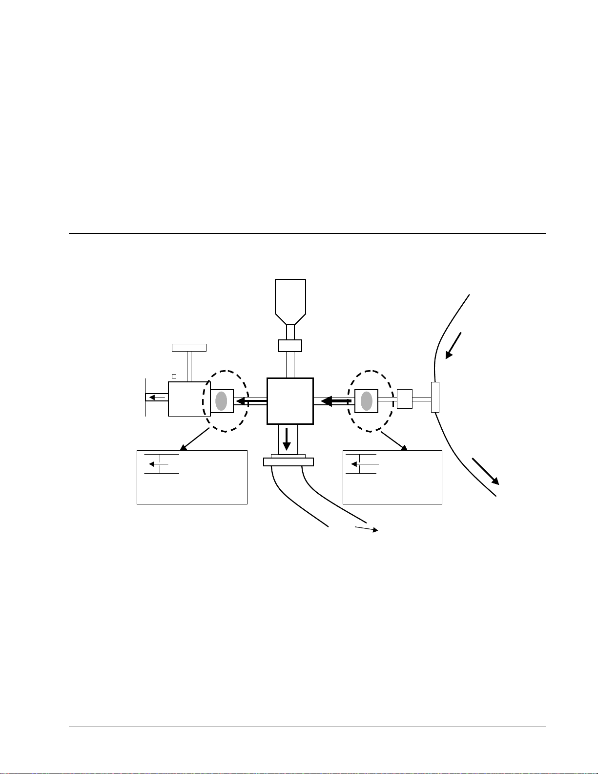
The sampling interface for the Real-Time Gas Analyzer (RTGA) is shown in Figure 1.
Figure 1: The 5000B RTGA sampling interface.
The standard sampling interface consists of a sampling tee and a sampling cross. Sample input
tubing is connected to the top of the sampling tee. One branch of the tee is connected to the
sampling cross through a sample orifice, while the other is a vent line for excess sample. Since only
a small fraction of the sample input will flow through the sample orifice into the sampling cross, the
bulk of the sample can be routed back into the process or vented.
A fixed orifice (30 µm i.d.) limits the amount of sample that is drawn. The first orifice (the sample
orifice) is in between the sampling tee and the sampling cross. One branch of the cross connects to
the large “bypass” vacuum pump (Pfeifer DUO-10M, Edwards RV12, or Edwards nXDS-10i). This
pump reduces the pressure in the cross and pulls the majority of the sampled stream out to waste.
A second leg on the cross allows a precision pressure transducer to read the cross pressure. This
signal can be used to adjust the data for changes in sample pressure.
To RV12 pump
To
MSD
(10-6 Torr)
Pressure
Transducer Process
Stream in
Out to
vent
Molecular flow
Orifice 50
Sonic Flow
Orifice 30
Isolation
Valve
.
.
[RS232 interface]
Minimum
40ml/min flow
(350 for trace)
~0.5
Torr Sample Tee
Sample
Orifice
HV
Orifice
To RV12 pump
To
MSD
(10-6 Torr)
Pressure
Transducer Process
Stream in
Out to
vent
Molecular flow
Orifice 50
Orifice 50
Sonic Flow
Orifice 30
Orifice 30
Isolation
Valve
..
..
[RS232 interface]
Minimum
40ml/min flow
(350 for trace)
~0.5
Torr Sample Tee
Sample
Orifice
HV
Orifice

Theory of Operation
8 Diablo 5000B Real-Time Gas Analyzer Getting Started Manual
The final branch contains a second orifice (the high vacuum orifice) that further limits the amount of
sample reaching the mass spectrometer and allows the mass spectrometer to maintain the
necessary high vacuum (typically 1x10⁻⁶ Torr). The default orifice diameter is 50 µm for this stage.
Flow then passes through a vacuum isolation valve that is useful for troubleshooting and
maintenance. The outlet of the isolation valve connects to the mass spectrometer interface and
directs the sampled stream to the ionization region in the mass spectrometer.
The two orifices and the large vacuum pump allow the high-vacuum mass spectrometer to sample a
gaseous input directly with minimal dwell time. A thermal jacket envelopes the sampling tee and the
cross to maintain the desired sample temperature until high vacuum is encountered. The Watlow
EZ-Zone temperature controller regulates this temperature to the user-selected set point.
If excess sample is to be vented, it is recommended that some length of tubing be attached to the
outlet of the sample tee to limit back diffusion of air into the cross.
Additional Interface Options
Please contact Diablo Analytical for additional sample interface options and their suitability for your
application. These include:
Fast-response Interface: a low-volume tee configuration that provides T90 response times
of < 3 seconds.
Low-flow Direct Interface: A direct interface designed for very low flow rates (typically <= 4
mL/min, determined by the sample pressure and orifice diameter).
Vacuum Sampling Interface: A direct interface that is designed for samples at a slight
vacuum.

Diablo 5000B Real-Time Gas Analyzer Getting Started Manual 9
Setting up the Hardware
Connecting sample lines
Caution:
Particulates and condensed liquids or droplets in the sample stream can
plug the 30-μm sample orifice, which will then need to be replaced. It is the
responsibility of the user to ensure that their sampling system is designed
to eliminate particulate and liquid prior to the sample gas stream reaching
the RTGA sampling tee.
The sample input and output connections are standard 1/16-inch Swagelok fittings. By using 1/16-
inch tubing, the dwell time of the sample line can be minimized without introducing a large pressure
drop. The sample input is connected to the top of the interface and the vent or process return is
connected to the bottom of the interface. To make a new fitting connection, make sure the tube is
fully inserted into the fitting body. Finger-tighten the fitting and then tighten ¾ of a turn with a 5/16-
inch wrench on the compression nut and a 5/16-inch wrench on the adapter body.
Figure 2: A photograph of the RTGA interface with the sampling tee identified.
If necessary, user-supplied fittings can be used to adapt process lines to the 1/16 inch required for
the interface. Heating the sample lines is the responsibility of the user.

Setting up the Hardware
10 Diablo 5000B Real-Time Gas Analyzer Getting Started Manual
Changing Orifice Disks
The RTGA uses two laser-drilled orifice disks to provide pressure reduction in the sampling
interface. The orifice disks that are supplied with the RTGA are listed in Table 1. Note that orifice
disks with other diameters are available for special applications.
Table 1: Orifice disks included with the 5000B RTGA.
*The default orifice configuration Installed in the interface at the factory.
Note: The 350-um high-vacuum orifice is not compatible with all applications. In particular, it is not
compatible applications requiring hydrogen or helium tuning.
Important:
Due to the nature of the seal produced by the VCR fitting, the orifice
disks cannot be reused. Replacement orifice disks can be purchased
from Diablo Analytical.
Figure 3: A photograph of the RTGA interface with the VCR fittings containing the sample and
high-vacuum orifice disks identified.
The standard factory orifice configuration is applicable to a broad range of applications. However,
either orifice disk can be easily replaced using the following procedure.
1. Close the isolation valve to the MSD.
Orifice
Diameter (μm)
Description
Part Number
30*
Standard sample orifice
D3163-20500
50*
Standard high vacuum orifice
D3163-20510
350
Special high vacuum orifice for
trace analysis.
D3163-20550

Setting up the Hardware
Diablo 5000B Real-Time Gas Analyzer Getting Started Manual 11
2. Note the current interface pressure, and then unplug the power cord to the MKS PDR 2000
pressure controller.
3. Turn off the bypass sampling pump.
4. Loosen the VCR fitting that contains the orifice disk that you want to change. The orifice
disk is used as the seal in the VCR fitting. You will need two open-end wrenches: 3/4" and
5/8". Once you have unscrewed and separated the two nuts, you can pull them away from
each other and expose the orifice disc, which will be sandwiched between the two ends of
the fittings.
5. Remove the old orifice from between the fittings. It is possible you may have to loosen the
screw that attaches the interface bracket to the side of the MSD in order to separate the two
fittings far enough for the high-vacuum orifice to be removed.
6. Insert the new orifice disk in between the two fittings - use gloves to handle the orifice so
that you don't get fingerprints on the surface. This step can be a little tricky, and it
sometimes helps to place the orifice inside the large hex nut first, and the slide it over the
mating fitting.
7. Re-tighten the two nuts - you should hold the large nut stationary while tightening the small
nut. You can use the small hole drilled in the side of the large nut to confirm that the orifice
is in place and didn't drop out. Don't over tighten the VCR fittings - tighten it 1/8 turn past
finger tight.
8. If you loosened the interface bracket screw, re-tighten it.
9. Turn the bypass pump back on.
10. Plug the power cord back into the pressure controller and wait for the reading to stabilize.
Make sure that the interface returns to a similar vacuum pressure as before.
11. Open the isolation valve and perform an autotune and check for leaks.
Temperature controller operation and maintenance
The 5000B RTGA is shipped with a custom temperature controller console using a Watlow EZ-Zone
Controller.
Caution:
The maximum temperature for the interface is 200 °C. Do not enter values
higher than this into the controller. It is possible damage the heater
blanket and/or the MSD electronics if you use interface temperatures
higher than 200 °C!
Setting up the Hardware
12 Diablo 5000B Real-Time Gas Analyzer Getting Started Manual
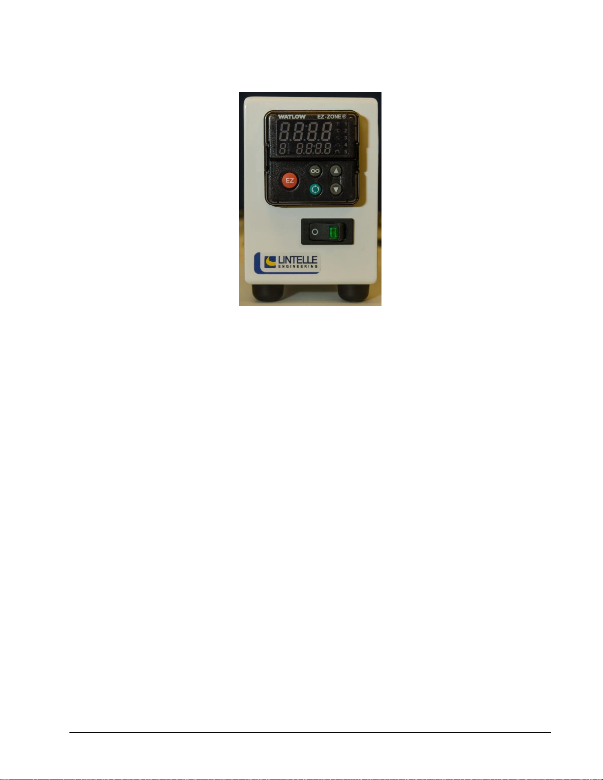
Watlow EZ-Zone Controller
Figure 4: The front panel of the Watlow EZ-Zone Temperature Controller.
Changing the interface temperature
Simply press the gray up/down arrows on the right side of the temperature controller to adjust the
interface temperature set point. The upper numeric display shows the actual interface temperature,
while the lower numeric display shows the current set point.
Setting the Temperature Display Units
Note: The temperature controller is set to units of ºC at the factory.
Use the following procedure to set the units of the displayed temperature (ºC or ºF). Refer to Figure
4. 1. Press and hold both of the gray up/down arrow buttons for approximately 6 seconds until
the controller shows “A1” in the top display, and “SEt” in the bottom display. Note that you
will have to continue to hold the buttons after “oPEr” appears in the lower display.
2. Press the down arrow key until the top display reads “9LbL” (for global). The bottom
display should still read “SEt”
3. Press the green advance button until “C_F” is in the bottom display.
4. Press the gray up arrow key until the desired temperature units are shown in the top
display (“C” or “F”).
5. Press the gray infinity key (“∞”) until you reach the “home” display with the actual
temperature in the top display and the set point in the lower display.
Auto-tuning the controller
Note: The temperature controller is auto-tuned at the factory at a temperature of 120 ºC.
If the actual temperature does not stabilize at the set point or significantly overshoots or
undershoots the set point, it may be necessary to “tune” the controller using the autotune function.
Please refer to Figure 4.

Setting up the Hardware
Diablo 5000B Real-Time Gas Analyzer Getting Started Manual 13
1. Start with the temperature controller off and the interface and heater blanket cold. In
addition, it is important to make sure that the heater blanket is tightly secured and in good
contact with the RTGA interface.
2. Turn on the temperature controller and press the up/down arrow buttons to select the
desired interface temperature set point.
3. Press the green advance button until the bottom display reads “AUt 1”.
4. Press the up arrow button until the top display reads “Yes” then press the infinity button to
return to the temperature display.
5. The unit should begin autotuning. The upper display will flash between “tUn 1” and the
actual temperature until the autotune is complete.
Caution:
During autotuning, the controller will cycle the temperature around a
value of 90% of the current temperature set point. Consequently, you
should be careful not to tune at a set point that results in the temperature
cycling above 200 °C.
Pressure sensor operation and maintenance
To connect the pressure sensor to the cross
Note: This procedure is normally performed at the factory during assembly of the interface.
The pressure sensor is connected to the sampling cross with standard VCR4 fittings. To install a
new pressure sensor, loosen the cap fitting with a 5/8- and 3/4-inch or adjustable wrenches. Use
the lint-free gloves included with the MSD ship kit to handle the VCR4 gasket. Carefully place the
gasket on top of the cross fitting and place the pressure sensor on top of the gasket. This is best
done if the female fitting on the pressure sensor is slid back to allow the sealing surfaces to meet.
Finger-tighten the male and female nut assemblies. Using the wrenches, tighten the fittings an
additional 1/8 of a turn.
To connect the pressure sensor controller to the PC
Two cables are included with the MKS PDR 2000 pressure sensor controller. One (part no.
CB628S-3-10) is for connecting the sensor to the controller while the other (part no. CBPDR-1-10)
is for connecting the controller to the PC. An appropriate power cord is also included for the sensor
controller.
To configure the pressure sensor controller:
The controller has no On/Off switch so, once it is plugged in, the LED display will light and begin to
flash. To obtain accurate readings, the PDR 2000 Controller needs to be configured for the sensor
in terms of units, full scale, and zero.
1 To begin configuration, press the [Select] button on the controller. The display will flash OFF
and the LED indicator will be on SetPt1 Hi.
Setting up the Hardware
14 Diablo 5000B Real-Time Gas Analyzer Getting Started Manual
2 Press [Select] four times so that Units is indicated. Use the [Raise] and [Lower] buttons to
scroll through the options until Torr is shown. Press [Select] to choose Torr; the controller
will advance to the Calibrate option.
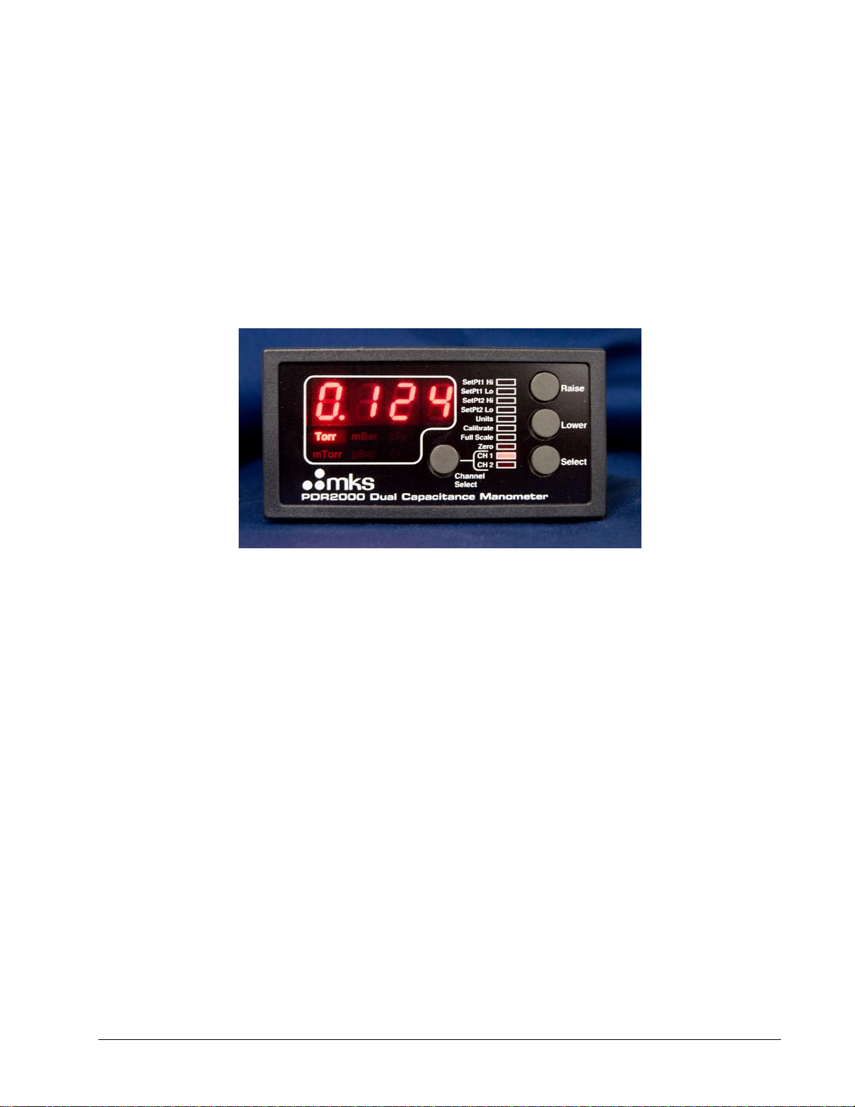
3 Press [Select] again to move to the Full Scale option. Make sure that the controller is set to
the pressure sensor channel, CH1 or CH2. If you are using a single-channel cable to
connect the pressure sensor to the controller, then select CH 1. If you are using a dual-
channel cable, then select the channel that is identified in the label on the cable that is
connected to the sensor. Use [Raise] and [Lower] to set the full scale value to that of the
sensor. For the sensor supplied with the RTGA interface, this value is typically 2 torr.
However, you should confirm this by referring to the label printed on the side of the pressure
sensor.
Figure 5: The MKS PDR2000 pressure controller.
The controller is now configured and ready to be zeroed.
To zero the pressure sensor:
Note: The pressure transducer is zeroed at the factory. You should only re-zero the sensor if you
are certain that the calibration has drifted.
Important: Do not zero the pressure sensor if there is a leak anywhere in the interface assembly.
To check the current zero setting, make sure that the roughing pump for the interface is on. Close
the isolation valve to the mass spectrometer and plug the sample input and output branches on the
sampling tee. Allow the roughing pump to run for at least 15 minutes. The pressure should stabilize
near 0 Torr.
Important: The pressure should have been powered and heating for at least 4 hours before
attempting to zero the signal.
The pressure sensor can be zeroed in two places. A zero adjustment is located on top of the
transducer itself and can be turned to zero the pressure reading with a small flat-blade screwdriver
(MKS 728A sensor) or by pressing a recessed zero button (MKS AA02A sensor). Zeroing can also
be done on the controller front panel. Make sure that the channel selection is on the pressure
sensor to be zeroed (typically CH 1). Press the [Select] button until the Zero LED is lit. Using the
[Raise] and [Lower] buttons, adjust the readout to 0.000 torr.
If the sensor still cannot be zeroed, please refer to the MKS manual included with your system.
Table of contents
Other Diablo Measuring Instrument manuals


