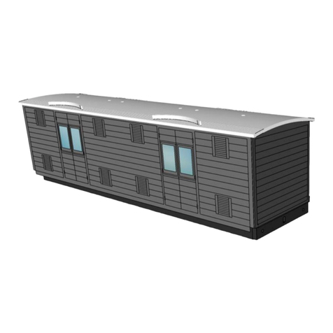
Diagram 3D D277 User manual

Great Northern Railway (GNR)
Third Brake (D277)
4mm scale (“OO” “EM” or “P4”)
GN04-D277
GNR
Third Brake (D277)
Website:
www.Diagram3D.com
Includes Smartframe.
Adhesive, paint not included. Wheels, axleguards, buffers etc. not included.
4mm scale kit suitable for “OO” “EM” “P4” etc.
Laser cut
MDF and card kit

www.Diagram3D.com
Assembly Instrucons
Great Northern Railway Third Brake (D277)
4mm scale (“OO” “EM” or “P4”)
© Copyright 2021 Diagram3D, All
rights reserved
Page 1
Introduction
Contents of this
kit
MDF Parts
MDF parts are supplied pre-cut, partially attached to the panel which preserves
their integrity and ensures that the right parts are present. Please do not separate
the parts until it is time to use them.
MDF Parts
SmartFrame
Upper and lower
frame plus align-
ment clips.
MDF Parts
1x ceiling
2 x stretchers
2 x solebars
6 x roof support
6 x plain partition
1 x glazing stop
1 x guard end
1 x floor
1 x step end
Cardboard panels
The card panels are
packaged within the
SmartFrame for protec-
tion.
The card panels are
identified by the printed
legend on the panels
e.g. “Side 1 of 2” etc.
Cardboard panels – a total of 7 panels as described below:
There are four layers for the sides.
There are three layers for the ends.
Layer Description
Layer 1 Window Frames and droplights
Layer 2 Coach side
Layer 3 Middle and upper panelling
Layer 4 Lower panels beading detail
3D printed
Parts. A 3D printed roof (PLA random colour) , 2 x duckets (guards lookout)
Glazing
Acrylic glazing:
2x guard inserts, 2 x side glazing
2x end glazing
Layer Description
Layer 2 Brake End Outer, ducket (2)
Layer 3 Brake End panelling, ducket panelling, Coach End
Layer 4 Brake End beading, ducket beading, Coach End
panelling, steps, ducket tops

www.Diagram3D.com
Assembly Instrucons
Great Northern Railway Third Brake (D277)
4mm scale (“OO” “EM” or “P4”)
© Copyright 2021 Diagram3D, All
rights reserved
Page 2
Not included
Adhesive to attach the parts. PVA is recommended for the MDF parts.
Craft knife, Clamps, weights or other tools.
Paint and filler
Wheels, bearings, Buffers, couplings etc.
Intended Audience This kit is intended to reduce the time, complication and labour associated with the
construction of a detailed model of a carriage body using accurate pre-cut layers
which can be conveniently assembled in the supplied SmartFrame without special-
ist knowledge to give the same quality, or better, as traditional methods.
This is not a complete kit of parts. The choice of underframe and other details is
left to the modeller.
Hints on assembly
Separate parts by
cutting the reverse
side of the fret.
Pre-assemble and
check parts at each
stage.
Seal Cardboard com-
ponents.
Video and Gallery
Separating MDF components cleanly is more easily accomplished by completing
the half etched portions on the reverse of the fret rather than cutting from the front.
Do not separate components from layers until assembly is complete or instructed
to do so.
At each stage, once the required components have been separated from the frets,
test the assembly without glue to ensure that the parts are trimmed correctly and fit
properly before final assembly with adhesive.
Allow as much time as needed for the adhesive to set.
Fill any gaps and smooth surfaces for optimal results
It is advised that cardboard parts are sealed before assembly.
The assembly steps below are strong recommendations but should not be
taken as definitive or prescriptive.
Copyright Statement The entire contents of this document including but not restricted to the text,
images, drawings and components, method of construction, design and
intellectual content are the copyrighted property of Diagram3D. No part of
this document or design may be used altered or copied without the express
written consent of the design and copyright owners. This document was
originally published in 2021 CE.
Current Documents The current version of documentation for this and any other of our products
can be downloaded from www.Diagram3D.com in PDF format.
Feedback
We welcome your comments and suggestions, especially images of models “in
progress” or completed.

www.Diagram3D.com
Assembly Instrucons
Great Northern Railway Third Brake (D277)
4mm scale (“OO” “EM” or “P4”)
© Copyright 2021 Diagram3D, All
rights reserved
SmartFrame
Preparation
(Applies to all
versions of
SmartFrame)
Total prepara-
tion and as-
sembly time
about 2
minutes.
Attach the clips to the bottom section of the SmartFrame as shown below:
Hint: Partially insert the clips into the slots and gently press the clips into position on
each side. An extra clip is provided. Avoid excessive pressure. Visit our website for
further constructional information including a video and gallery of models.
SmartFrame
General Hints
on using the
SmartFrame
The following diagram illustrates how to use the SmartFrame:
Position the layers of the same description in ascending order on the lower frame
beginning with the first layer. The layers have the legend “1 of x”, “2 of x” and so on.
Hint: Do not force the individual layers into position, assemble each layer at an angle
so that one side is in position and then gently position the other side into place. When
in position, extra pressure can be applied with rubber bands or “bulldog clips” on the
ends of the frame.
Page 3

www.Diagram3D.com
Assembly Instrucons
Great Northern Railway Third Brake (D277)
4mm scale (“OO” “EM” or “P4”)
© Copyright 2021 Diagram3D, All
rights reserved
Page 4
Carriage
Sides
Total preparation
and assembly
time about 5
minutes.
Allow sufficient
time for the
adhesive to dry
thoroughly
There are four layers for the sides. Insert these into the SmartFrame in order as de-
scribed above.
Apply adhesive and put aside until dry. Hint: The individual layers can be painted in
advance to simulate the window frames, main body and lining detail. When thoroughly
dry, detach the carriage sides using a sharp craft knife.
To form the tumblehome, use a section of tubing and gently roll the cardboard on a
rubber mat or similar surface. Alternately the tumblehome can be formed by using
finger-pressure against a suitably curved surface. Hint: Practice this on some scrap
card first.
Carriage
Ends
Total preparation
and assembly
time about 5
minutes.
Allow sufficient
time for the
adhesive to dry
thoroughly
There are four layers for the ends.
Insert these layers into the SmartFrame in order as described above.Apply adhesive and put aside
until dry. Hint: The individual layers can be painted in advance. The steps can now be detached and
place into the pre-cut holes individually in one end. The other end has communication cord equipment.
When thoroughly dry, detach the coach ends from the frame using a sharp craft knife
”Exploded”
Diagram
MDF Body
Shell
Total preparation
and assembly
time about 10-15
minutes.
Allow sufficient
time for the
adhesive to dry
thoroughly
Insert the partitions into the floor and glue into position. When set, attach the ceiling, side stretch-
ers and ends as shown below. Attach the glazing stop as shown below.
Hint: This is an appropriate time to paint and otherwise complete the interior of this model. Note: GNR third class
compartments had green rep upholstery. First Class had Blue upholstery. Smoking compartments had “drab”
upholstery according to contract specifications produced in the late 19th century.
Layer Description
Layer 1 Window Frames and droplights
Layer 2 Coach side
Layer 3 Middle and upper panelling
Layer 4 Lower panels beading detail
Layer Description
Layer 1 Brake End Inner
Layer 2 Brake End Outer, ducket(2)
Layer 3 Brake End panelling, ducket panelling, Coach End
Layer 4 Brake Ends Beading, ducket beading, Coach End panelling,
steps, ducket tops
The diagram shows the
main components of
this kit. The sides and
ends are pre-printed
and assembled as
described above.
The body is assembled
from MDF components.
The roof is 3D printed.

www.Diagram3D.com
Assembly Instrucons
Great Northern Railway Third Brake (D277)
4mm scale (“OO” “EM” or “P4”)
© Copyright 2021 Diagram3D, All
rights reserved
Page 5
Glazing &
final asembly
Total prepara-
tion and as-
sembly time
about 20
minutes.
Allow sufficient
time for the adhe-
sive to dry thor-
oughly
Note that this vehicle is not symmetric over its length so there is only one way
to position the roof.
Attach the sides to the body, taking care to align with the floor and allow to set.
Finally the ducket is attached to the centre of the vehicle. The curve of he ducket matches
the tumblehome.
The long window glazing bars supplied fit into the slots (one per side) which are pre-cut
into the partitions.
The end panels overlap the sides and fits into the recess in the roof under the moulded
cornice. Attach the ends taking care to centralise these components with the roof.
Roof
Total prepara-
tion and as-
sembly time
about 15
minutes.
Allow sufficient
time for the adhe-
sive to dry thor-
oughly
The 3D printed roof is designed to fit over the ceiling and attach to the
(optional) roof supports which locate in the ceiling. It is possible to make the
roof removable.
The roof will need some cleaning up and final painting before installation.
Although positioning holes are provided for ventilators throughout, vehicles
were fitted with alternate ventilators and lighting throughout their working lives
and a reference photograph will assist in determining which, if any, of the venti-
lators should be used for a given era.
The cornices were originally “teak colour”.
Underframe
The underframe is assembled by inserting the lugs on the solebars into the
corresponding holes in the floor of the vehicle.
The bogies are assembled according to the instructions in the kit D3D-06 which
is suitable for this vehicle.
Suitable wheels for “OO” are D3D-02 (four axles Mansell wheels).
Paint the 3D printed ducket overlay with
a suitable shade of “teak” - an orangey
brown colour. The pre-printed overlay /
panelling is attached to the outer sur-
face.
As shown, the small glazing pieces snap
into the 3D printed ducket lengthways.

www.Diagram3D.com
Assembly Instrucons
Great Northern Railway Third Brake (D277)
4mm scale (“OO” “EM” or “P4”)
© Copyright 2021 Diagram3D, All
rights reserved
Page 6
Historical
Notes
Originally designated as E48 and later as diagram 277, this short 45 foot coach was one of several types which
were designed by Howlden for the GNR in the late 1890’s. Twelve of these vehicles were in service in the early
20th century. The carriage was a logical extension of existing design on the GNR. It had a wooden underframe.
This vehicle is described in “Historic Carriage Drawings” Volume 1 by N. Campling. ISBN 1 899816 04 6 page
94.
Some example vehicle numbers for the GN period were:
366, 791, 808, 1628, 1635, 1645 which became 4366, 4791… 41645 at grouping.
No. 366 was rebuilt as a bullion van. These were long lived vehicles, most survived until nationalisation of the
railways in 1948 and beyond, including all the vehicles quoted above.
Underframe This was a bogie coach. The diagram wheelbase was 28 feet 11½ inches between
bogie centres. They were equipped with gas lighting, vacuum brakes and heating
apparatus. Originally they were equipped with Fox’s pattern bogies and later on with
standard Gresley bogies
Finally…
Congratulations on completing this kit. We hope you enjoyed making it as much as
we did.. If you enjoyed making this kit then take time to visit www.Diagram3D.com to
find similar items. Our website has free downloads of historical information. Down-
loadable assembly instructions for all of our products
Email: info@Diagram3D.com E&OE document updated Feb. 2022
GNR livery was varnished teak with gold lettering
and lining shaded blue. Earlier livery had the class
designation with the GN crest in the lower panel of
the door. In later years this was replaced by a large
numeral. Eventually, post-grouping, the class
designation numeral moved to the lower panel, the
crest and lining was omitted for surviving stock. It
was customary for a “pattern coach” to be provided
for inspection by external contractors.
In 1896, Moore’s Journal noted that GNR teak
vehicles were of uniform colouring, unlike other
companies that used varnished teak.
According to contract specifications the under-
frame was painted “teak” colour, ironwork was
black and the roof was painted white. However
a section of the visible roofline was painted
“teak” colour.
Depending on the frequency of washing the
visible roof colour could be anything from “teak”
to black, giving rise to various rumours about
the colour of GNR roofs and the apparent
discrepancy in colour between main line and
suburban stock. After 1905 or thereabouts
onwards roofs were painted white.
Other Diagram 3D Toy manuals
