Dialight Medium Intensity Instruction manual

Document No: 9100-127-1958-99 Rev F
Release Date: 10/8/15
1501 Route 34
South, Farmingdale, NJ 07727 Tel: (732) 919-3119 Fax:
(732) 751-5778 www.dialight.com
•DO NOT let any supply cords touch hot
surfaces higher than cord ratings.
•DO NOT mount near gas or electric heaters
•Equipment should be mounted in locations and
at heights where it will not be subjected to
tampering by unauthorized personnel.
•The use of accessory equipment not
recommended by the manufacturer may cause
unsafe conditions.
•DO NOT use this equipment for other than
intended use.
•DO NOT look into the Infrared (IR) LEDs. These
five IR LEDs on top of the unit (if applicable) will
not appear to be ON, but can be verified using
most digital cameras.
•Pictures are required for
commissioning the install. Failure to
provide could VOID all warranties
SAVE THESE INSTRUCTIONS!!
•The operation and maintenance must be carried
out by authorized personnel.
•Repairs and Installation must only be carried out
by a qualified electrician.
•Only genuine Dialight replacement parts must be
used when unforeseen repairs are required.
•Observe the national safety rules and regulations
during installation!
•Earth Grounding is required throughout the
install process. Failure to do so could void all
warranties!
•No alterations should be done without the
agreement from Dialight Corp. Alterations other
Than written in this manual will void all
warranties.
Instructions must be kept with the system installed
Introduction:
This manual is for orientation of the controller, configuration and definitions of the Dual
Strobe system or Dual Strobe + Infrared (IR) system.
Refer to the installation manual for the following information
•Installing the Controller and the pre drilled holes
•Dimensions of the Controller
•Securing the cables to the structure
•Connection of either AC or DC input voltages
•Connection of the Side lights and calibration
•Photocell connections
•Flashhead connections for both the 4 conductor and the 8 conductor versions
•Proper bonding of the Strobe cable
•Mounting the Flashhead.
Medium Intensity Quick Start Manual
READ AND FOLLOW ALL SAFETY INSTRUCTIONS

Document No: 9100-127-1958-99 Rev F
1501 Route 34 South, Farmingdale, NJ 07727 Tel: (732)
919-3119 Fax: (732) 751-5778 www.dialight.com
Included in this manual:
•System overview
•Installation Tips and requirements
•System Descriptions
•RS485 Communication Connections
•Installing the RS485 to additional power supplies
•Controller layouts
•Navigating the LCD Display oLCD startup display screens oSetup Screens
(Configuration) oMain Menu Screens oManual Lighting inspection test
•Controller Status LED’s
•Dry contact connections
•Controller electrical Parameters
•Resetting, ext sync option, and serial numbers
•Replacement part numbers
•Display Events and Alarm Descriptions
•Alarm list and possible causes
System Overview:
Document No: 9100-127-1958-99 Rev F
1501 Route 34 South, Farmingdale, NJ 07727 Tel: (732)
919-3119 Fax: (732) 751-5778 www.dialight.com
Installation Tips and requirements:
For the Mains cable, it is recommended that the electrician or installer calculate the wire
requirements based on the amount of Flash heads being installed. It is recommended
that no install utilizes less than 16AWG wire with at least a 90ºC temperature rating. See
electrical parameters.
For RS485 cabling; 3 cores of 18AWG, drain wire plus a shield and braid for adequate
grounding and signals are required. RS485 is only required for E1+1 and larger
structures where multiple Strobes are required.
Cable between the Flash head and the controller must be a minimum of 14AWG and 4
conductors with foil and braid. Maximum distance between the controller and the Flash
head is 630feet.
NOTE: Failure to do any of the above could void all factory warranties. If in doubt please
contact your sales agent or representative.
During installing on the tower proper grounding techniques should be utilized.
The system has built in Lightning and RF immunity at each section, but for it to be
effective proper ground connection techniques must be used. For more details or
contact your local sales rep.
System Descriptions that are covered in the manual:
D1RW-C13-009-CTR = consists of:
•D1RW-FH009 (Flash Head)
•D1RW-CTR009 (Controller/Supply)
Gen5 dual red/white with AC input , 48volt
sidelights and 8 conductor flash head cable
required
D1RW-C13-409-CTR = consists of:
•D1RW-FH409 (Flash Head)
•D1RW-CTR409 (Controller/Supply)
Gen5 dual red/white with AC input , 48volt
sidelights and 4 conductor flash head cable
required
D1RW-C14-009-CTR = consists of:
•D1RW-FH009 (Flash Head)
•D1RW-CTR049 (Controller/Supply)
Gen5 dual red/white with 48VDC input , 48volt
sidelights and 8 conductor flash head cable
required
D1RW-C14-409-CTR = consists of:
•D1RW-FH409 (Flash Head)
•D1RW-CTR449 (Controller/Supply)
Gen5 dual red/white with 48VDC input , 48volt
sidelights and 4 conductor flash head cable
required
D1RW-C17-009-CTR = consists of:
•D1RW-FH009 (Flash Head)
•D1RW-CTR079 (Controller/Supply)
Gen5 dual red/white with AC input , AC sidelights
and 8 conductor flash head cable required
D1RW-C17-409-CTR = consists of:
•D1RW-FH409 (Flash Head)
•D1RW-CTR479 (Controller/Supply)
Gen5 dual red/white with AC input , AC sidelights
and 4 conductor flash head cable required
D1CW-C13-409-CTR = consists of:
•D1CW-FH409 (Flash Head)
•D1CW-CTR409 (Controller/Supply)
Gen5 dual red/white + Infrared (IR) with AC input ,
48volt sidelights and 4 conductor flash head cable
required
D1CW-C14-409-CTR = consists of:
•D1CW-FH409 (Flash Head)
•D1CW-CTR449 (Controller/Supply)
Gen5 dual red/white + Infrared (IR) with 48VDC
input , 48volt sidelights and 8 conductor flash head
cable required

Document No: 9100-127-1958-99 Rev F
1501 Route 34 South, Farmingdale, NJ 07727 Tel: (732)
919-3119 Fax: (732) 751-5778 www.dialight.com
RS485 Communication Connections:
NOTE: The below is common between all the controllers covered in the manual.
The connection of the RS485 cable is vitally important to the operation of the system.
This connection provides all the events and alarms to the Master controller that is being
used with the installation.
Factory connected wiring color code:
Boards are Labeled Description Color Code
Label “A”
Communications “A”
Grey
Common
Common for RS485
Yellow
Label “B”
Communications “B”
Blue
Option 1: RS485 consisting of 3 conductors, a drain wire and foil shield and braid.
Install Cable Connected to Description Color Code
Conductor 1
Label “A”
Communications “A”
Grey
Conductor 2
Common
Common for RS485
Yellow
Conductor 3
Label “B”
Communications “B”
Blue
Drain wire
Ground stud
Ground
Bare wire
Foil Shield and
Braid
Clamping terminal
Ground
Connected when
cable enters the
enclosure and must
be secured to the
plate
Option 2: RS485 consisting of 2 Conductors, a drain wire and either a shield or
braid is used.
Install Cable Connected to Description Color Code
Conductor 1
Label “A”
Communications “A”
Red
Drain Wire
Common
Common for RS485
Bare Wire
Conductor 2
Label “B”
Communications “B”
Black
Shield or Braid
Clamping Terminal
Ground
Connected when
cable enters the
enclosure and must
be connected to
plate
WARNING: For Color Codes not shown the installer must take note of the colors used
for these connections since it is required that all A, Common and B terminals be
connected the same throughout the system.
Document No: 9100-127-1958-99 Rev F
1501 Route 34 South, Farmingdale, NJ 07727 Tel: (732)
919-3119 Fax: (732) 751-5778 www.dialight.com
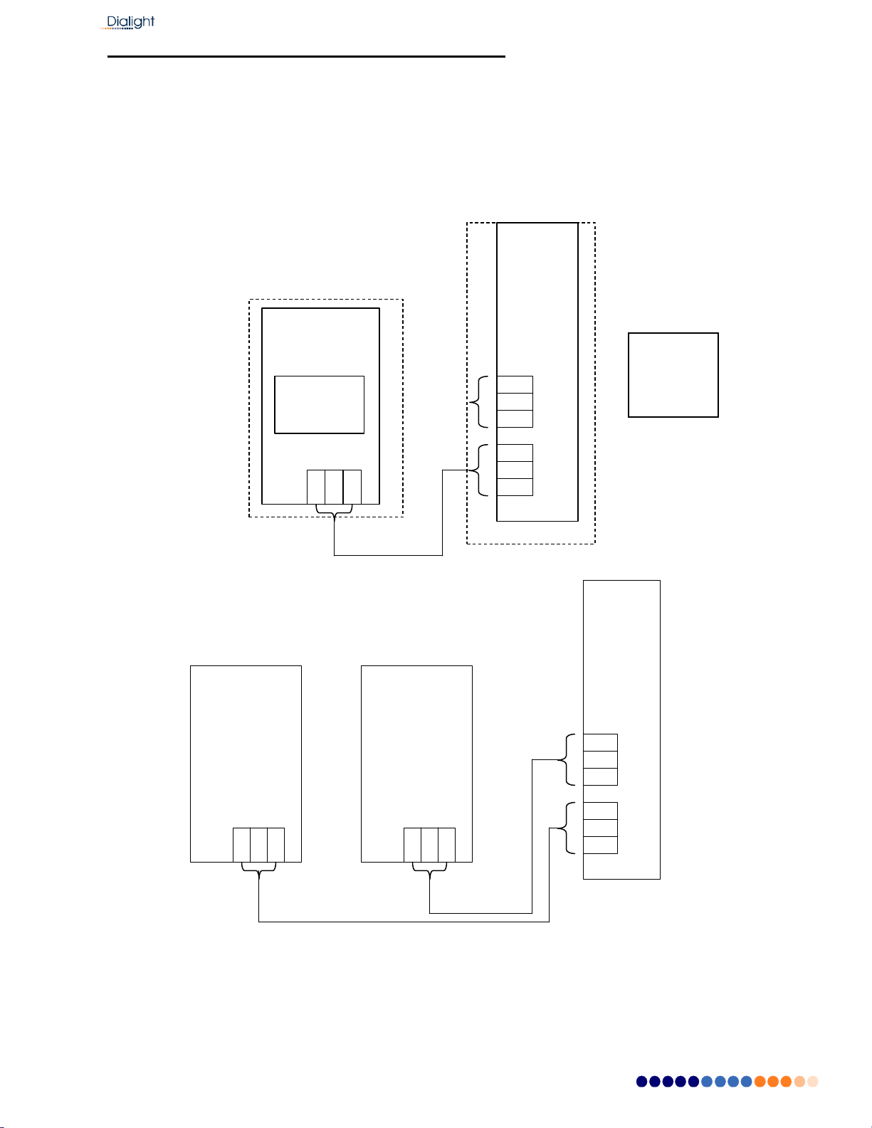
Installing the RS485 to additional power supplies
NOTE: For an E1 system there is no externally connected RS485.
NOTE: For structures lager than the above additional external communications need to
be added between the RS485 surge board and the translator boards in each of the
additional power supplies.
NOTE: For systems larger than E2 daisy chaining between the translator boards is
required.
NOTE: Translator boards are located in power supply enclosures NOTE:
The controller translator board is to be set to zero.
RS485
Located in
Controller
E2, D2 and A2
Translator
Board#1
Translator
Board#2
RS485
Junctio
n
Board
E1+1,
D1+1 and A1+1
RS485
Junction
Board
Translator
Board#1
Located in
power
supplies

Document No: 9100-127-1958-99 Rev F
1501 Route 34 South, Farmingdale, NJ 07727 Tel: (732)
919-3119 Fax: (732) 751-5778 www.dialight.com
D1xW-C13-x09-CTR Controller:
Requirements
NOTE: See electrical parameters for power consumption
Attach output of Photocell to side light monitor board (Marker) board J4
Connect the RS485 to the Junction Board when additional power supplies are
connected.

Document No: 9100-127-1958-99 Rev F
1501 Route 34 South, Farmingdale, NJ 07727 Tel: (732)
919-3119 Fax: (732) 751-5778 www.dialight.com
D1RWC17409CTR Controller:
Requirements
NOTE: See electrical parameters for power consumption
Attach output of Photocell to monitor board (Marker) board J4
Connect the RS485 to the Junction Board when additional power supplies are
connected.

Document No: 9100-127-1958-99 Rev F
1501 Route 34 South, Farmingdale, NJ 07727 Tel: (732)
919-3119 Fax: (732) 751-5778 www.dialight.com
LCD Start up Display Screens:
Once power is turned on the next 2 screens will be displayed automatically.
The Startup Screen displays:
Dialight MI Ctrl
REV. x Build: xx
NOTE: The Site manager and Installer should take a note of this screen including the
REV number and the Build number if any future troubleshooting is required. x’s indicate
revision levels and will appear as numbers on the display.
The Initializing Screen:
This screen shows a countdown for the initial 15 flashes for E and D type structures For
A red only systems the countdown starts at 45.
NOTE: In some cases this screen will go back to the Startup screen if synchronization
was faulty.
Initial 15 Flashes In
Process

Document No: 9100-127-1958-99 Rev F
1501 Route 34 South, Farmingdale, NJ 07727 Tel: (732)
919-3119 Fax: (732) 751-5778 www.dialight.com
Setup Screens:
These screens are used for properly configuring system based on the structure type that
is being installed. By using the “UP” and “DWN” buttons the user or maintenance
personnel can view and edit the configuration as applicable by pressing the “ENTR”
button after the selecting the desired choice the next screen will be entered.
Configuration Type Screen:
A) To change configuration of controller go to ‘Config Type’ screen’ and press
“ENTR”. This will enable you to select either an “E” “A” or “D” tower type. Sub
categories such as E1, E2 etc. will be addressed later in the configuration
menu.
CONFIG TYPE X
‘Enter to change’
B) Use the “UP” and “DWN” buttons to scroll and select tower style A, D, or E.
Then press “ENTR”.
NOTE: If ‘Tower Style D’ is selected, the system will automatically proceed to
step F, skipping steps D and E since side markers (L810) are not used in D style
configurations. Any information previously in the system as indicated in omitted
steps will be changed to “0” if switched back to an E or A style configuration and
will have to be re-entered to match what is installed on the tower.
NOTE: System will reset when tower style is changed.
Tower style = E
‘enter’ to change
C) Select for the presence of an External GPS using the “UP” and “DWN” buttons,
“YES” indicates an external GPS is being used, “NO” is the standard
configuration without an external GPS. Press “ENTR” after selection.
Ext GPS = NO
u/d=chg, enter=done

Document No: 9100-127-1958-99 Rev F
1501 Route 34 South, Farmingdale, NJ 07727 Tel: (732)
919-3119 Fax: (732) 751-5778 www.dialight.com
D) Select the number of Side Marker (L810 or RTO) Tiers that are connected to
the system. 0 through 4 can be selected; the number input shall represent the
number of tiers present. Press “ENTR”.
Num of 810 TIERS=0
u/d=chg, enter=done
E) Select the number of Side Marker s (L810’s, RTO’s) that will connected to P1
(Tier 1) 0 through 4 can be selected, then press “ENTR”
NOTE: Repeat for ports 2 through 4.
NOTE: Each port represents one tier.
NUM 810 P1/T1= 0
u/d=chg, enter=done
F) Select the number of beacons (864/5’s) that will be connected to the system. 1
through 9 beacons can be supported. Press “ENTR”
Number of 864/5 = 1
u/d=chg, enter=done
G) Select the number of side light boards that are connected to the system, 1
through 9 and the press “ENTR”.
NOTE: Additional sidelight monitor boards are available for special applications;
most configurations will only have one board and this will remain set to “1”
Number of SD BDs=1
u/d=chg, enter=done

Document No: 9100-127-1958-99 Rev F
1501 Route 34 South, Farmingdale, NJ 07727 Tel: (732)
919-3119 Fax: (732) 751-5778 www.dialight.com
H) Select the status of side lights. Use “UP” and “DWN” buttons to change from
STEADY, DISABLED and FLASHING, depending on what is needed of the
sidelights.
NOTE: This is a global change that will affect all tiers of sidelights; individual
tiers are not able to have statuses changed.
L810 stat = STEADY
u/d=chg, enter=done
L810 stat = Disabled
u/d=chg, enter=done
L810 stat = Flashing
u/d=chg,
enter=done
I) Select red mode flash rate of the beacons as well as the sidelights when
specified to be flashing as indicated in step H. Selections available are 20, 30,
and 40. Use “UP” and “DWN” buttons to change, and them press “ENTR”
NOTE: Factory default is 30fpm
NOTE: This is a global change that will affect all tiers of sidelights at once.
NOTE: This change will not affect white flashes.
Flash per min = 30
u/d=chg, enter=done
J) If sidelights are to be calibrated at this time (if not calibrated as per the previous
section of this manual or the quantity or wiring of sidelights has changed since
previous calibration), use “UP” and “DWN” buttons to change from “NO” to
“YES”, and then press “ENTR.” The system will reset and the sidelight board
will perform its calibration sequence.
NOTE: This step should only be selected if all tiers of sidelights are fully installed
and connected to the controller.
RECAL L810 = NO
u/d=chg, enter=done
Document No: 9100-127-1958-99 Rev F
1501 Route 34 South, Farmingdale, NJ 07727 Tel: (732)
919-3119 Fax: (732) 751-5778 www.dialight.com
K) If the Photocell mode transition alarm (18 hour alarm) is not needed as an
alarm this selection can disable it.
NOTE: Typically used where there long day or night operations.
Selecting YES: If the photocell does not detect day or night after 18 hours, the
system will alarm after 18 hours and will switch to Day mode. To clear this alarm the
system requires a local reset or a forced operation change locally or remotely.
Selecting NO: After 18 hours of not transitioning the system will log an event in the
log but the system will continue to operate normally based on light conditions. No
alarm via dry contact or mod bus will be generated.
Trans PEC Alrm = YES
u/d=chg, enter=done
Trans PEC Alrm = NO
u/d=chg, enter=done
Use “UP” and “DWN” buttons to change from “NO” to “YES”, and then press “ENTR.”
L) The Beacon can be made steady burn in Red night mode
BCN Steady RNite= NO
u/d=chg, enter=done
Once the selection for the Beacon steady red Night is completed the next screen to be
displayed is the “Config Type”.
NOTE: Typically used outside of the US. FAA regulations require the beacon to be
flashing so most typical installation will have this selection set to “NO” to ensure a
flashing beacon.
Document No: 9100-127-1958-99 Rev F
1501 Route 34 South, Farmingdale, NJ 07727 Tel: (732)
919-3119 Fax: (732) 751-5778 www.dialight.com
After about 2 minutes the system will reset on its own to save the configured
information.
CONFIG TYPE X
‘Enter to change’
The Reset button located in the middle bottom of the board can also be pressed to reset
the system.
Resetting is required so the controller saves the configured information to throw alarms
on changes occurring during the operation of the system.
Main Menu Screens:
The next screens are paged through using the “UP” and “DWN” buttons. The user or
maintenance personnel can view and edit the configurations as applicable by pressing
the “ENTR” button to enter into each main menu screen.
Pressing the “CLR” in the selected screens takes the user back to the main screens.
Upon resetting or powering and powering up the system this is the first screen that is
displayed.
•Status Screen –Config type:
CONFIG TYPE X
‘Enter to change’
•Screen: Tower style:
This screen displays what the Base Controller has been configured for, if the amount of
beacons configured does not match what is actually connected then alarms will be
generated as “config” alarms. Only powered fixtures and fixtures connected to the
RS485 will be detected. The “B y” in second line will indicate the firmware level of main
controller.
NOTE: If the installer selects 3 beacons and only 1 is powered AL1 (config ERR) will be
lit and recorded in the alarm log.
Tower Style: X X
86X ,X 810 B y
Document No: 9100-127-1958-99 Rev F
1501 Route 34 South, Farmingdale, NJ 07727 Tel: (732)
919-3119 Fax: (732) 751-5778 www.dialight.com
•Screen: Mode of operation –Day or Night
NOTE: These modes change according to the user’s photocell operation. There are no
options for preprogramming mode change times.
Mode: Options are Day or Night , T= controller temperature (C)
Active: Options are Wht or Red
NOTE: On this screen the controller can be forced in DAY or NIGHT (using the
push buttons located under the down button marked White and Red). NOTE:
S3 will blink till system is restored to normal operation
MODE: Night T=X C
ACTIVE: RED 864
MODE: Night Forced
‘Clear to restore
•Status Screen - Alarms:
This screen allows the user access to the Alarm Log. By pressing the “ENTR” button,
current and previous alarms the system has encountered are able to be viewed, starting
with the most current alarm. Alarms can be scrolled through using the “UP” and “DWN”
buttons. Each alarm occurrence is dated and time stamped. Up to 999 alarm entries
can be stored in the controller.
NOTE: If an Alarm is found, the Status screen will change from “NORMAL” to “ALARM”
thus indicating there is an active Alarm.
By pressing “ENTR” you will be able to view alarm logs. Time stamps are actual times
that the alarm occurred. Refer to interpretation of the logs for further details.
Status: Normal
‘Enter’ to view Alrm
Status: ALARM
‘Enter’ to view Alrm
•Date and Time Screen - Setting the real time clock:
By selecting “ENT” the user can set the actual time and date of the Base Controller.
NOTE: Date and time settings are stored in the controller; if power is lost, internal
battery backup ensures settings will not be erased.
MMM DD,YY “Time”
‘Enter’ to set Clock
Document No: 9100-127-1958-99 Rev F
1501 Route 34 South, Farmingdale, NJ 07727 Tel: (732)
919-3119 Fax: (732) 751-5778 www.dialight.com
•Manual Lighting Inspection Screen
The user can perform a manual lighting inspection to ensure proper operation of the
system in its entirety.
NOTE: Discreet and Modbus alarms will be generated during this test, a if NOC is
actively monitoring at the time of test, they will see the generated alarms.
Test will time out after 2 minutes of no user input during the manual test. The test relies
on user input to complete the necessary checks.
Manual LI TEST
‘enter’ to Test
•Status Screen Event Log:
This screen allows the user access to the Event Log. By pressing the “ENTR” button,
current and previous events the system has encountered are able to be viewed, starting
with the most current event. Events can be scrolled through using the “UP” and “DWN”
buttons. Each event occurrence is dated and time stamped.
NOTE: While viewing the event log, real time events are to be viewed by pressing the
“CLR” button to exit the log and then press the “CLR” key to return to log, indicating the
latest recorded event.
Press ‘Enter’ Key to
view event log.
After this display when pressing the up button the Config display is the next one shown.

Document No: 9100-127-1958-99 Rev F
1501 Route 34 South, Farmingdale, NJ 07727 Tel: (732)
919-3119 Fax: (732) 751-5778 www.dialight.com
Manual Lighting Inspection Test for Firmware Versions B6 or higher:
The user can perform a manual lighting inspection to ensure proper operation of the
system in its entirety.
NOTE: Discreet and Modbus alarms will be generated during this test, if NOC is actively
monitoring at the time of test, they will see the generated alarms.
Test will time out after 2 minutes of no user input during the manual test. The test relies
on user input to complete the necessary checks.
NOTE: A lighting inspection can be done remotely but the Auto lighting inspection is
required. The auto does not require covering of the photocell or pressing the selected
mode during the auto test.
System needs to be in Day mode before test is started
Press “ENTR” to initiate LI test
Manual LI TEST
‘enter’ to Test
Press enter
MLI ‘CLR’ to exit Push
WHT BTN
Press’ TEST WHITE’ button located under the ‘Down’ on the LCD control board A
series of test will be automatically performed.
Manual LI TEST IN
PROCESS WHT
Cover photocell; wait until beacon turns Red or White Night.
This can be confirmed by monitoring AL8 on the dry contact board. Once the AL8 is off
the system is in Night mode.
Wait for 15 flashes and then press the TEST RED button.
MLI ‘CLR’ to exit
push RED BTN

Document No: 9100-127-1958-99 Rev F
1501 Route 34 South, Farmingdale, NJ 07727 Tel: (732)
919-3119 Fax: (732) 751-5778 www.dialight.com
The displays will indicate the test is in process and state which mode of night operation
the system is presently configured to.
A and E Structures D Structures
Manual LI TEST IN
PROCESS RED
OR
Manual LI TEST IN
PROCESS NWHT
Once the test is complete one of the 2 displays will be shown.
OR
Manual LI TEST
LIT DONE
System will return to configuration screen when test is completed.
System will reset within 5 minutes after the completion of the test
NOTE: If the test is not completed due to prompts not being followed, tests will time out
after 5 minutes and display:
Manual LI TEST LIT
NOT DONE
Manual LI TEST
PASS : )
Manual LI TEST FAIL
: (

Document No: 9100-127-1958-99 Rev F
1501 Route 34 South, Farmingdale, NJ 07727 Tel: (732)
919-3119 Fax: (732) 751-5778 www.dialight.com
After the Lighting inspection (LI) test is done the user can check the LI list in the Alarm
log and it should be as follows:
For an “E” style system: For a “D” style system:
1. LIT log start 1. LIT log start
2. 865 SYNC 1 ACT 2. 865 SYNC 1 ACT
3. TRNS RS232 1 ACT 3. TRNS RS232 1 ACT
4. TRNS Comm 1 ACT 4. TRNS Comm 1 ACT
5. TRNS Comm 1 CLR 5. TRNS Comm 1 CLR
6. TRNS RS232 1 CLR 6. TRNS RS232 1 CLR
7. 865 SYNC 1 CLR 7. 865 SYNC 1 CLR
8. 1 865 W25% BACT 8. 1 865 W25% BACT
9. 1 865 W25% 1 CLR 9. 1 865 W25% 1 CLR
10. 1 865 W25% 2 CLR 10. 1 865 W25% 2 CLR
11. L810 CAL error ACT 11. PCE LOST ACT
12. L810 CAL error CLR 12. SDLT Comm ACT
13. 1 ALL L810 TX ACT 13. SDLT Comm CLR
14. PCE LOST ACT 14. PCE LOST CLR
15. SDLT Comm ACT 15. LIT log end
16. SDLT Comm CLR
17. PCE LOST CLR
18. 1 ALL L810 TX CLR
19. 1 864 R25% ACT
20. 1 864 R25% CLR
21. LIT log end
For an “A” style system:
1. LIT log start
2. 865 SYNC 1 ACT
3. TRNS RS232 1 ACT
4. TRNS Comm 1 ACT
5. TRNS Comm 1 CLR
6. TRNS RS232 1 CLR
7. 865 SYNC 1 CLR
8. 1 ALL L810 TX ACT
9. L810 CAL error ACT 10. L810 CAL error CLR
11. PCE LOST ACT
12. SDLT Comm ACT
13. SDLT Comm CLR
14. PCE LOST CLR
15. 1 ALL L810 TX CLR
16. 1 864 R25% ACT
17. 1 864 R25% CLR
18. LIT log end

Document No: 9100-127-1958-99 Rev F
1501 Route 34 South, Farmingdale, NJ 07727 Tel: (732)
919-3119 Fax: (732) 751-5778 www.dialight.com
Controller Status LED’s; Located on Main Controller Board with LCD display
Note: Actual colors shown may not match system being installed Note:
There are labels located on the enclosure door stating the alarm
descriptions.
STATUS LED ASSIGNMENTS
S7
S6
S5
S4
S3
S2
S1
COMM SYNC 25% LED ALL 810 OFF Photocell
EXT SYNC Heartbeat
Failure
Failure Failure Failure Failure Day/Night
Failure Flashes
RED RED RED RED RED
AMBER GREEN
Relay Board Alarm Dry Contact LED’s:
STATUS LED/dry contact ASSIGNMENTS
AL8 AL7 AL6 AL5 AL4 AL3 AL2 AL1
PEC
MODE
L 810
FAILURE
Trans
COMM
Day/Night
transition
PEC LOST
25%
FAILURE
Sync
Config or
COMM
Amber
Red
Failure
Red
Failure
Red
* not used
when PEC
Trans is set
to NO
Red
Red
For
either
white or
red fails
Failure
Red
Failure
Red
Dry Contact monitoring Installation:
Cable requirements:
A minimum of 22AWG wire should be used for connecting the relays

Document No: 9100-127-1958-99 Rev F
1501 Route 34 South, Farmingdale, NJ 07727 Tel: (732)
919-3119 Fax: (732) 751-5778 www.dialight.com
1. The relays can be wired individually or multiplexed for alarm monitoring.
2. The relays can be wired as normally open or normally closed.
To monitor the dry contacts on the relay board, the dry contact readers will have to be
wired in to the relay contacts marked (Com, NO, and NC). Relays are marked as if
there is no power is applied to the system.
WARNING: It is highly recommended that by using a multi-meter the dry contacts be
measured for “open” or “closed” by using the OHM setting on the meter.
The relays can measured for open or closed with power applied to the base controller.
NOTE: If only one dry contact reader is present then the relays need to be multiplexed
together to give one output as shown below:
NOTE: If less than 7 dry contact readers then 1 or more dry contacts can be
multiplexed together.
NOTE: Dry contact Relay 8 is only for Day and night monitoring and not Alarm relay
but indication of the mode the system is currently in.
Wiring for Multiplexing a single dry contact reader.
relay7 relay6 relay5 relay4 relay3 relay2 relay1
To Reader (input1) To Reader (input2)
Controller Box Electrical Parameters:
Wattage below is with no side lights attached; wattage from side lights must be added.
Nominal Supply Voltage (VAC)
Conditions
Peak Watts
230Vac 50/60Hz
Day mode (E1 system)
90W
C N
O
N
C
C
N
O
N
C
C N
O
N
C
C N
O
N
C
C N
O
N
C
C N
O
N
C
C N
O
N
C
This manual suits for next models
8


