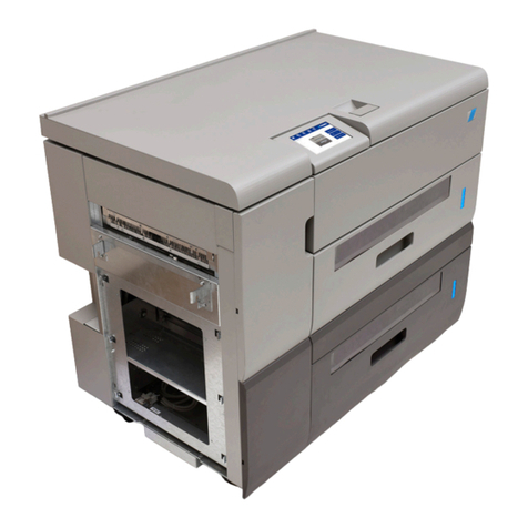
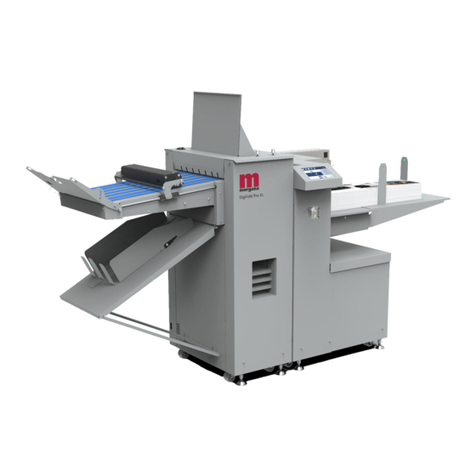
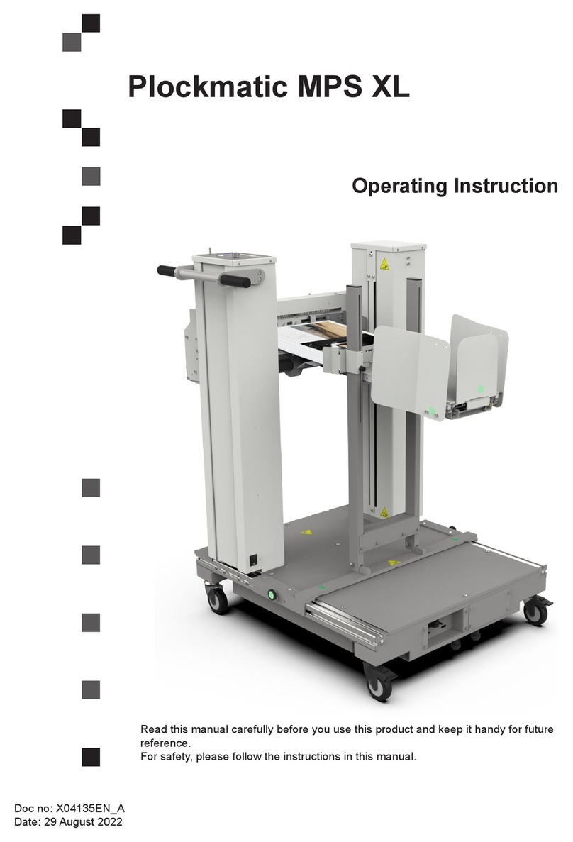
Plockmatic Morgana PowerSquare 160 User manual

Plockmatic PowerSquare™ 160
Right-to-Left Service Training Workbook
for Konica Minolta
Issue 1. Published October 2018. Amended 27/02/2019.
Name: ............................................................................
Doc No. x05081

© Watkiss Automation Limited 2018-2019
All Rights Reserved.
Reproduction, adaptation, or translation without prior written permission is prohibited, except as
allowed under the copyright laws.
Warranty
The information contained in this document is subject to change without notice. Watkiss Automation
Limited makes no warranty of any kind with regard to this material, including, but not limited to, the
implied warranties of merchantability and fitness for a particular purpose.
Watkiss Automation Limited shall not be liable for errors contained herein or for incidental or conse-
quential damage in connection with the furnishing, performance or use of this material.

iPlockmatic PowerSquare™ 160 - Service Training Workbook
CONTENTS
1 Introduction . . . . . . . . . . . . . . . . . . . . . . . . . . . . . . . . . . . . 1
1.1 Conventions in this workbook . . . . . . . . . . . . . . . . . . . . . . . . . . . . 3
1.2 Illustrated Parts Catalogues (IPC) . . . . . . . . . . . . . . . . . . . . . . . . . 4
2 Product Overview . . . . . . . . . . . . . . . . . . . . . . . . . . . . . . . 6
2.1 Paper Flow . . . . . . . . . . . . . . . . . . . . . . . . . . . . . . . . . . . . . . . . . . 6
3 Description of Operation . . . . . . . . . . . . . . . . . . . . . . . . . 9
3.1 Paper Enters the System. . . . . . . . . . . . . . . . . . . . . . . . . . . . . . . . 9
3.2 The Gathering Area - Online . . . . . . . . . . . . . . . . . . . . . . . . . . . . 11
3.3 The Gathering Area - Hand Feed . . . . . . . . . . . . . . . . . . . . . . . . 13
3.4 Paper Transport. . . . . . . . . . . . . . . . . . . . . . . . . . . . . . . . . . . . . . 14
3.5 The Staple Heads and Clinchers. . . . . . . . . . . . . . . . . . . . . . . . . 14
3.6 Fold and Form . . . . . . . . . . . . . . . . . . . . . . . . . . . . . . . . . . . . . . . 15
3.7 Trim . . . . . . . . . . . . . . . . . . . . . . . . . . . . . . . . . . . . . . . . . . . . . . . 16
3.8 Outfeed and Stacker . . . . . . . . . . . . . . . . . . . . . . . . . . . . . . . . . . 17
4 User Interface (GUI) - Operator Menu . . . . . . . . . . . . . . 18
4.1 Introduction . . . . . . . . . . . . . . . . . . . . . . . . . . . . . . . . . . . . . . . . . 18
4.2 Illustration - Online. . . . . . . . . . . . . . . . . . . . . . . . . . . . . . . . . . . . 18
4.3 Illustration - Hand Feed . . . . . . . . . . . . . . . . . . . . . . . . . . . . . . . . 19
4.4 Window Controls . . . . . . . . . . . . . . . . . . . . . . . . . . . . . . . . . . . . . 20
4.5 The Paper Size Window . . . . . . . . . . . . . . . . . . . . . . . . . . . . . . . 21
4.6 The Book Size Window . . . . . . . . . . . . . . . . . . . . . . . . . . . . . . . . 22
4.7 The Advanced Window . . . . . . . . . . . . . . . . . . . . . . . . . . . . . . . . 23
4.8 The Messages Tile . . . . . . . . . . . . . . . . . . . . . . . . . . . . . . . . . . . 24
4.9 The Message Window . . . . . . . . . . . . . . . . . . . . . . . . . . . . . . . . . 25
4.10 The Job Window . . . . . . . . . . . . . . . . . . . . . . . . . . . . . . . . . . . . . 25
4.11 Key Operator Tiles and Windows . . . . . . . . . . . . . . . . . . . . . . . . 26
4.12 System Status Window . . . . . . . . . . . . . . . . . . . . . . . . . . . . . . . . 27
5 Advanced Operation . . . . . . . . . . . . . . . . . . . . . . . . . . . . 28
5.1 Paper quality and machine performance. . . . . . . . . . . . . . . . . . . 28
5.2 Alignment and Level . . . . . . . . . . . . . . . . . . . . . . . . . . . . . . . . . . 28
continued . . .
Plockmatic PowerSquare™ 160, Service Training Workbook for KonicaMinolta
Issue 1, October 2018. Amended 27/02/2019.
ii Plockmatic PowerSquare™ 160 - Service Training Workbook
5.3 Clear paper jams . . . . . . . . . . . . . . . . . . . . . . . . . . . . . . . . . . . . . 28
5.4 Book Quality and Machine Specifications . . . . . . . . . . . . . . . . . . 29
6 User Interface - Service Overview . . . . . . . . . . . . . . . . . 30
6.1 Access Service Level . . . . . . . . . . . . . . . . . . . . . . . . . . . . . . . . . 30
7 Installation . . . . . . . . . . . . . . . . . . . . . . . . . . . . . . . . . . . . 33
8 Machine Areas . . . . . . . . . . . . . . . . . . . . . . . . . . . . . . . . 34
8.1 Introduction . . . . . . . . . . . . . . . . . . . . . . . . . . . . . . . . . . . . . . . . . 34
8.2 Connecting Bridge . . . . . . . . . . . . . . . . . . . . . . . . . . . . . . . . . . . . 34
8.3 Infeed/Gathering Area Module . . . . . . . . . . . . . . . . . . . . . . . . . . 35
8.4 Paper Transport - Book Gathering . . . . . . . . . . . . . . . . . . . . . . . 36
8.5 Paper Transport - Book Transport. . . . . . . . . . . . . . . . . . . . . . . . 37
8.6 Staple and Clinch . . . . . . . . . . . . . . . . . . . . . . . . . . . . . . . . . . . . 38
8.7 Fold and Form . . . . . . . . . . . . . . . . . . . . . . . . . . . . . . . . . . . . . . . 39
8.8 Trim . . . . . . . . . . . . . . . . . . . . . . . . . . . . . . . . . . . . . . . . . . . . . . . 41
8.9 Outfeed and Stacker . . . . . . . . . . . . . . . . . . . . . . . . . . . . . . . . . . 42
9 Preventative Maintenance . . . . . . . . . . . . . . . . . . . . . . . 43
9.1 Operator Maintenance. . . . . . . . . . . . . . . . . . . . . . . . . . . . . . . . . 43
9.2 Technical Maintenance . . . . . . . . . . . . . . . . . . . . . . . . . . . . . . . . 43
10 Power and Control . . . . . . . . . . . . . . . . . . . . . . . . . . . . . 44
10.1 Power . . . . . . . . . . . . . . . . . . . . . . . . . . . . . . . . . . . . . . . . . . . . . 44
10.2 Control . . . . . . . . . . . . . . . . . . . . . . . . . . . . . . . . . . . . . . . . . . . . . 45
10.3 Component Locations . . . . . . . . . . . . . . . . . . . . . . . . . . . . . . . . . 47
10.4 DFA . . . . . . . . . . . . . . . . . . . . . . . . . . . . . . . . . . . . . . . . . . . . . . . 51
11 Software . . . . . . . . . . . . . . . . . . . . . . . . . . . . . . . . . . . . . . 52
12 Replace Trimmer Blade . . . . . . . . . . . . . . . . . . . . . . . . . 54
13 PSQ160 Accessories . . . . . . . . . . . . . . . . . . . . . . . . . . . 54
14 Product Specifications . . . . . . . . . . . . . . . . . . . . . . . . . . 55
15 Quality Tolerances . . . . . . . . . . . . . . . . . . . . . . . . . . . . . 58
16 PSQ160 Site Requirements . . . . . . . . . . . . . . . . . . . . . . 59
17 Glossary of booklet making terms . . . . . . . . . . . . . . . . 66

Introduction
Plockmatic PowerSquare™ 160 - Service Training Workbook 1
1. Introduction
Figure 1. Plockmatic PowerSquare™ 160. Right to left with connecting bridge.
Figure 2. Plockmatic PowerSquare™ 160. Hand feed model.

Introduction
2Plockmatic PowerSquare™ 160 - Service Training Workbook
The Plockmatic PowerSquare™ 160 is an innovative, complete book making
system for digital print applications. In a single machine it combines the four
processes of stapling, folding, spine forming and trimming to produce
SquareBack™ books up to 160 pages.
With a maximum book thickness of 8 mm (40 sheets/80gsm), the PSQ160 is a fast
and cost effective alternative to perfect binding or tape binding. Since it will also
produce books from only a few sheets, it provides a single book-making solution for
documents from 8 through to 160 pages.

Introduction
Plockmatic PowerSquare™ 160 - Service Training Workbook 3
1.1 Conventions in this workbook
The Plockmatic PowerSquare™ 160 is referred to by its code of PSQ160.
this is an instruction or task that the trainer will do
this is a task that the student will do
This workbook refers to the following PSQ160 Service Manual:
• Issue 1, 07/02/2019

Introduction
4Plockmatic PowerSquare™ 160 - Service Training Workbook
1.2 Illustrated Parts Catalogues (IPC)
The Plockmatic PowerSquare™ 160 is made from these modules:
The modules are split into assemblies. Each assembly is shown as an exploded
diagram. See Figure 3.
PSQ160
IPC Code Description
P16x Complete M/C
- PBAS Base Machine
- PWAS Waste Bin Assembly
- - PDEC Deck assembly
- - PSK- Stacker
- - PGUI GUI and Hinge Assembly
- - PFOL Folder Assembly
- - PFRL Fold Rollers Assembly
- - PFOR Spine Former
--PSTO Trim Stop
- - PTRI Trimmer
- - POUT Outfeed
- PIN1 Infeed Assembly
x denotes manufacturer version
Connecting Bridge
IPC Code Description
PCRx Bridge cabinet, R2L
- PBR/7 Bridge Rotator
- PUD1/2/3/4 Up/Down Lifts
x denotes manufacturer version
Optional Units
IPC Code Description
PBS- PowerSquare Book Stacker (optional)
P2T- PowerSquare 2-Knife Trimmer (optional)

Introduction
Plockmatic PowerSquare™ 160 - Service Training Workbook 5
Figure 3. Extract from PDEC. Fig.11 - active tamper gate
• Every exploded diagram is followed by the related part number information. The
part number information is given for the top level assembly, sub-assemblies and
components where available. See Figure 4.
Figure 4. Extract from PDEC. Fig.11. Part number information.
AExploded diagram
ATop-level assembly
BSub assembly
CComponent level
-XO 3'(&),*$&7,9(7$03(5*$7(
F
D
E
G
D
G
F
E
A
:
28
Part No.Item Description Qty. Fig.
FIG.11 - ACTIVE TAMPER GATE ASSEM BLY PSQ160 DECK -PDEC LAST EDIT:30 NOV 17
Fig11 894-638 P.ASSY, (PDEC) ACTIVE TAMPER GATE 1
1 894-639 • P.ASSY, (PDEC) TA MPER PIVOT DRIVE SIDE 1
1a 100-334 • • SCREW, SKT HD CAP, M2.5x10mm STAINLESS 1
1b 160-202 • • WASHER, M2.5 FORM A STAIN LESS 1
1c 258-223 • • ST STEEL, (PDEC) PIVOT LOCATION PLATE 1
1d 266-088 • • SHAFT,(PSQ) ACTIVE-GATE PIVOT PIN 1
•
2 100-406 • SCREW, SKT HD CAP, M3x8 HT ZP 4
3 160-002 • WASHER, M3 FORM A BZP 12
4 150-033 • NUT, M3 NYLOC-TYPE T BZP 6
5 315-775 • PLASTIC,(PSQ) ACTIVE-GATE PIVOT BLOCK 1
6 894-640 • P.ASSY, (PDEC) TA MPER PIVOT PLATE 1
6a 266-088 • • SHAFT,(PSQ) ACTIVE-GATE PIVOT PIN 1
6b 258-223 • • ST STEEL, (PDEC) PIVOT LOCATION PLATE 1
6c 160-202 • • WASHER, M2.5 FORM A STAIN LESS 1
6d 100-334 • • SCREW, SKT HD CAP, M2.5x10mm STAINLESS 1
•
7 150-035 • NUT, M5 NYLOC- TYPE P BZP 2
8 160-003 • WASHER, M5 FORM A BZP 4
9 281-927 • STEEL, (PDEC) PCB MOUNTING BRACKET 1
10 900-258 • PCB ASSEMBLY, S TEPPER MTR INTERCONNECT 1
11 742-806 • CABLE ASSEMBLY , (PSTO) TRIM SENSOR 1
12 710-016 • ELEC-HARDWARE, CABLE TIE-small 7
13 160-001 • WASHER, M4 FORM A BZP 4
14 100-338 • SCREW, SKT HD CAP, M4 x 12mm STAINLESS 2
15 281-915 • STEEL, (PDEC) TAMPER MOTOR BRACKET 1
16 192-753 • GEAR, (PSTO) TAMPER DRIVE 28T 1MOD 1
A
B
C

Product Overview
6Plockmatic PowerSquare™ 160 - Service Training Workbook
2. Product Overview
2.1 Paper Flow
The sheets of paper leave
the printer and enter the
infeed of the connecting
bridge.
See Section 3.1
The paper is rotated in the
connecting bridge if
necessary.
See Section 3.1
The sheets of paper are
flipped upside down and
gathered into a set in the
gathering area.
See Section 3.2
When a set is complete it
is moved to the staple
position where it is
stapled. The staple heads
are underneath, the
clinchers are on top.
See Section 3.4
and Section 3.5

Product Overview
Plockmatic PowerSquare™ 160 - Service Training Workbook 7
The set is moved to the
fold position where the
fold blade pushes the set
into the spine form
clamp.
See Section 3.6
The fold blade lifts and the
form clamp closes. The
form roller creates the
SquareBack spine on the
book.
See Section 3.6
The fold rollers drive the
book down to the trim
infeed where the book is
driven onto the trim stop.
See Section 3.7
When driven onto the trim
stop, the book is clamped
in position. The fore-edge
of the book is trimmed by
the trimmer blade that
moves horizontally.
See Section 3.7

Description of Operation
Plockmatic PowerSquare™ 160 - Service Training Workbook 9
3. Description of Operation
After the PSQ160 is turned on, the operator either enters the paper size and
direction on the GUI or loads a previously saved job. Set thickness is handled
automatically by the PSQ160. When the job is gathered in the PSQ160, each sheet
is flipped upside down by the infeed drum, therefore the job must be printed ‘first-to-
last, face up’. See Figure 7. to Figure 9.
The PSQ160 is controlled by the printer and by a system of internal sensors.
3.1 Paper Enters the System
• When the print job starts, the printer sends a cycle-up signal to the PSQ160.
• Paper leaves the printer and enters the rotator module in the connecting bridge.
The paper is moved through the connecting bridge by belts into the gathering
area.
• Paper can be accepted from either ‘side-referenced’ or ‘centre-referenced’
printers. The connecting bridge translates the paper to ‘centre-referenced’ for the
PSQ160.
• When the page is in A4 portrait format, the paper can be rotated through 90° by
the turning-ball in the connecting bridge if necessary.
• A3 (17 x 11") and A4 (11 x 8½") landscape jobs move through the bridge without
rotation. The turning-ball is not in the paper path. The conveyor drive belt is at a
small angle to the sidelay and drives the paper against the sidelay.
Figure 5. A3 (11 x 17") paper moves straight through the connecting bridge
• A4 (8½ x 11") portrait jobs are rotated around the turning-ball. The paper is
driven against the sidelay by the angled, bridge drive-belt. The sidelay makes
sure the paper aligns to the centre reference line of the bridge.
A Gathering Area
B Sidelay
C Turning-ball
D A3 paper leaves the printer
E Bridge Drive Belt
A
B
C
D
E

Description of Operation
10 Plockmatic PowerSquare™ 160 - Service Training Workbook
Figure 6. A4 (8½ x 11") Portrait paper is rotated by the connecting bridge
• The drive belts are run from a stepper motor in the connecting bridge. The
connecting bridge axes are also adjusted by stepper motors.
• A combination of non-conductive belts and conductive-brushes in the connecting
bridge remove the static-electric charge from the paper. Sheets of paper with a
static-electric charge stick together and will not jog into a tidy book.
• After travelling through the rotator, the paper is raised to the height of the infeed
of the PSQ160 by an uplift module.
• An optical sensor in the rotator infeed sees that a piece of paper has entered the
rotator. Another optical sensor at the outfeed of the rotator sees when the paper
leaves the rotator. If the time between the operation of the sensors is too long,
then a flow error or paper jam in the rotator is indicated. The PSQ160 sends an
error message to the printer. The print job and the PSQ160 stop.
• An optical sensor in the uplift infeed sees that a piece of paper has entered the
uplift module. Another optical sensor at the outfeed of the uplift sees when the
paper leaves the uplift. If the time between the operation of the sensors is too
long, then a flow error or paper jam in the uplift is indicated. The PSQ160 sends
an error message to the printer. The print job and the PSQ160 stop.
• When a complete set is printed the printer sends an ‘end of set’ signal to the
PSQ160, which starts the PSQ160 operation.
• On the top of the connecting bridge is a tri-colour indicator. The tri-colour
indicator shows the machine status:
- Blinking green: Ready to receive a job
- Solid green: working
- Solid amber: operator intervention needed such as empty the trim bin
- Solid red: the machine is offline, e.g. changing paper size, or in an error state
- Flashing red: The GUI is unresponsive. The DFA has lost communication with
the GUI and generated the flashing red error. Reboot the PSQ160.
A Sidelay
B Turning-ball
C A4 portrait paper leaves the printer
D Bridge Drive Belt
E Gathering Area
A
B
C
D
E

Description of Operation
Plockmatic PowerSquare™ 160 - Service Training Workbook 11
3.2 The Gathering Area - Online
Figure 7. Paper enters the infeed face-up
Figure 8. Paper is gripped and rotated by the infeed drum
AInfeed
BPaper, face-up
CClamp
DInfeed drum
EGathering area
A
B
C
D
E

Description of Operation
12 Plockmatic PowerSquare™ 160 - Service Training Workbook
Figure 9. Paper face-down in the gathering area
See Figure 7. to Figure 9.
• When the paper enters the gathering area, a clamp on the rotating drum grips
the lead edge of the sheet.
• The paper is flipped upside down to ‘face-down’ orientation, released and
knocked-up against the endlay on the same side as the infeed. The opposite
endlay has an inbuilt side-tamper to assist with the knock-up.
• In the gathering area, the paper is placed between the endlays and sidelays. The
endlays and sidelays are adjusted by the PSQ160 to the measured paper-size
entered into the touch screen. Adjustments to the sidelays and endlays are
made with stepper motors.
See Figure 9.
• An active tamper gate in the front sidelay jogs the incoming sheets into a tidy set.
When the set is complete, the active tamper gate lifts to let the set move to the
staple position. The active gate is driven by a stepper motor.
• Optical sensors in the infeed, the gathering area and in the tumbler see when
paper is present. If the time between the operation of the sensors is too long or if
a sensor remains covered, then a flow error or paper jam in the gathering area is
indicated.
ASide-tamper
BActive tamper-gate
B
A

Description of Operation
Plockmatic PowerSquare™ 160 - Service Training Workbook 13
3.3 The Gathering Area - Hand Feed
Figure 10. The hand feed gathering area
• The required paper size is selected from the GUI and the endlays and sidelays
move to the correct position.
• Paper is placed into the gathering area between the endlays and sidelays. See
Figure 10.
• If the machine is configured for ‘Auto Sensor’, then after a preset delay, the set
will be progressed through the machine. If the machine is configured for ‘Manual
Button’, then the user must press the green manual button to start the
bookmaking process.
AEndlay
BSidelay
CSet in the gathering area
DManual button
B
A
C
D

Description of Operation
14 Plockmatic PowerSquare™ 160 - Service Training Workbook
3.4 Paper Transport
Figure 11. Belts, flights and sensor pins
• Flights (fingers) on the belts push the set through the machine from the
gathering area via the staple area and to the fold area.
• The belts run the length of the endlays and are moved by stepper motors. Each
endlay has two belts with flights that can move in opposite directions to increase
and decrease the distance between the flights according to the size of the book.
The belts can also run in the same direction to move the book through the
machine.
• The belts are independently driven by stepper motors.
• Each flight has a metal reference pin that interrupts optical sensors as the belts
move. From this, the machine knows the position of the flights and can then
adjust the position as needed for different sizes of paper.
• Additionally, one flight per side has a magnetic index pin that is seen by a sensor
and provides the index position.
3.5 The Staple Heads and Clinchers
• There are 2 staple heads that fire upward from below the deck. The clinchers are
mounted above the deck.
• The staple heads are in a fixed position, side-to-side, on the centre line of the
machine and form the datum from which measurements for the endlay set-up
are taken.
• The staple heads can move toward each other or away from each other along
the centre line of the machine to give a variable staple pitch. The clinchers move
to match the spacing of the staple heads. The staple head and clincher axes are
adjusted by stepper motors.
ALH endlay
BTop belt
CSensor pin
DFlight attached to the top belt
ESensor pin
FFlight attached to the bottom belt
GBottom belt
A
B
C
D
E
F
G

Description of Operation
Plockmatic PowerSquare™ 160 - Service Training Workbook 15
• When a set is delivered to the staple position, the clinchers are driven down by a
stepper motor until they contact the set. The steps needed to bring the clinchers
to the paper are counted and used to calculate the thickness of the book. This
data is used by the folder and former to give the correct depth of fold and spine
form.
• When the clinchers touch the set, the staple heads fire. The clinchers then rise to
release the set, which is transported to the folder area.
• An optical sensor in the staple area sees when paper is present. If the sensor
stays covered, then a jam is indicated.
3.6 Fold and Form
• When the set stops in the folder area, the folder blade is operated.
• The folder blade pushes against the centre line of the book - located by the
staples - and folds the book in half. The folder blade pushes the book to a
calculated depth between a pair of fold-rollers and into the form clamp.
• Each face of the form clamp has a horizontal, polyurethane strip that gives a
cushioned grip. The polyurethane strip is important for thin books because the
soft surface prevents the staple cutting through the front and back covers of the
book.
• The folder blade is held in the park position and released when the folder blade
needs to travel downward.
• Drive for the fold blade is by a stepper motor. Drive for the spine form clamp is
provided by the main motor and transferred to a drive shaft by a chain and
clutch.
Figure 12. Exploded diagram of the spine form clamp
• The fold blade retracts and the clamp closes on the book. The form roller rolls
along the spine of the book to create the SquareBack book. The pressure
applied is calculated by the PSQ160 or can be overridden on the touch screen
by the operator.
AClamp assembly
BForm roller
CForm roller end B sensor
A
B
C

Description of Operation
16 Plockmatic PowerSquare™ 160 - Service Training Workbook
• The form roller is transported on a carriage that runs along the carriage guide.
The carriage drive is by a stepper motor. When the carriage reaches the end of
the carriage guide, either the form roller end A or form roller end B sensor is
operated. If the carriage is stopped before either of the sensors is reached, the
carriage returns to the start position.
• The form roller is turned by a gear wheel that engages with a rack.
• When the spine is formed, the carriage stops at one end of the carriage guide
and the spine form clamp is released. The fold rollers rotate to drive the book
through to the trimmer infeed conveyors.
• An optical sensor in the fold area sees when paper is present. If the sensor stays
covered, then a jam is indicated.
3.7 Trim
Figure 13. Trim stop components
• The book is driven between two facing sets of conveyors in the trimmer infeed
onto the trim latch. The distance of the trim latch from the trimmer blade is
calculated by the PSQ160 according to the size of the job. The operator can
change the amount of trim from the touch screen if necessary. The trim axis is
adjusted by a stepper motor.
A900-258 interconnect PCB
BTrim latch drive motor
CTrim latch home sensor
D900-305 interconnect PCB
ETrim axis drive motor
FTrim axis home sensor
A
B
C
D
E
F
Other manuals for Morgana PowerSquare 160
1
Table of contents
Other Plockmatic Industrial Equipment manuals

Plockmatic
Plockmatic FeederPro 1000 User manual

Plockmatic
Plockmatic 510 User manual

Plockmatic
Plockmatic BM3000 User manual

Plockmatic
Plockmatic Pro XL User manual

Plockmatic
Plockmatic HCI3500 User manual

Plockmatic
Plockmatic HCI3500 User manual

Plockmatic
Plockmatic Morgana VFL Feeder User manual

Plockmatic
Plockmatic MPS XL User manual

Plockmatic
Plockmatic SF 4000 User manual