Hansen APPT08 Operating instructions

Specifications, Applications, Service
Instructions, & Parts
AUTO-PURGER®PLUS, APPT
Non-condensible Gas (Air) &
Water Purger for Ammonia
Bulletin APP-001f
SEPT 2016
For Models
APPT08, APPT16, APPT24,
AND APPTC
AUTO-PURGER®PLUS, APPT
SECTION 1 INTRODUCTION
Water contamination in an industrial ammonia refrigeration
system can lower system efficiency, and increase the
electrical costs required to run the system’s refrigeration
compressors. Ammonia refrigerant that is contaminated
with water requires a lower suction pressure to maintain
the same evaporator temperature than would pure ammonia
refrigerant. The requirement to maintain a lower suction
pressure than would be necessary if the water contamination
were removed is a waste of electrical energy.
For water removal, the AUTO-PURGER Plus has the
following capacities:
1% system water concentration – ½ gallon of water
removed per week,
5% system water concentration – 1 gallon of water removed
per day,
10% system water concentration – 3 gallons of water
removed per day,
20% or more system water concentration – 5 gallons of
water removed per day.
MATERIAL SPECIFICATIONS
Material of construction: steel, ASTM A53 Grade B, ASTM
A106 Grade B, ASTM A234 Grade WPB, ASTM A105,
ASTM A36
Safe working pressure: 400 psig (28 bar)
Operating temperature: -50F to +240F (-50C to +115C)
Internal volume: 0.7 cubic feet (20 liters)
Normal refrigerant inventory: 0.35 cubic feet (10 liters)
TABLE OF CONTENTS
Section 1 Introduction…………………….............Page 1
Section 2 Installation……………….....................Page 2
Section 3 Component Description……..............Page 6
Section 4 Purger Operation……………...............Page 19
Section 5 Service, Troubleshoot, Parts…..........Page 22
The AUTO-PURGER Plus is a totally automatic, electronically
controlled refrigerant noncondensible gas (air) and
water purger for reducing the energy costs of operating
an ammonia refrigeration system. All models are
preassembled, pre-wired, insulated, and include an
automatic water bubbler, a relief valve, and an isolation
service valve package. Installation requires piping the foul
gas line, low-pressure pumped-liquid line, low-pressure
liquid return line, suction line, water bubbler fill and drain
lines, relief valve vent line, water purge line to a customer
supplied container, a power connection, and wiring the
remote purge point solenoid valves. Purge point solenoid
valves must be purchased separately and must be a
minimum of ½” (13 mm) port size.
In addition to the APPT08, APPT16, and APPT24, a
computerized model—APPTC—is available where a
separate plant computer or programmable logic controller
(PLC) is used to independently operate the various remote
purge point solenoid valves.
The AUTO-PURGER Plus can operate over a wide range of
condensing pressures. This is important for refrigeration
systems that operate at low condensing pressures during
cold ambient conditions.
The number of purgers required for a system depends on
the number of installed purge points. Twenty-four purge
points is the maximum practical number per purger. For
example, a system with 24 points at 10 minutes per point
requires a 240 minute (4 hour) cycle. Each purge point
can be purged six times a day. If this is not adequate,
a second purger should be used and the purge points
divided equally between the two purgers.
In a system with normal noncondensible loads, all models
will handle a 750 ton (2600 kW) ammonia plant at suction
pressures below atmospheric pressure or a 1500 ton
(5300 kW) ammonia plant at positive suction pressures.
The amount of noncondensibles in the system is based
on many factors including age, maintenance practices,
and operating temperature.
.

2
APP-001f
SEPT 2016
MOUNTING INSTRUCTIONS
Mount the AUTO-PURGER Plus securely on a wall or
sturdy steel channels capable of supporting 450 lbs (205
Kg). Eight mounting holes in the frame are provided to
support the unit, see Figure 1. The unit should be located
in an accessible area, but away from moving equipment
that could accidentally come in contact with the purger.
Elevation with respect to condensers or high-pressure
receivers is not critical. Do not punch access holes in the
top of the control cabinet. Unused electrical entrances
to the enclosure must be sealed to protect the controls
from moisture.
The AUTO-PURGER Plus is normally installed in the
compressor room where it can be monitored, but also may
be installed outdoors where temperatures below freezing
are not anticipated. Outdoor use in areas near falling or
spraying water, or in constant high humidity areas is not
recommended.
Install the float switch assembly on the purger by removing
the packaging material and metal shipping tube. Slip the
float switch assembly over the enclosing tube being sure
the float switch assembly bottoms on the neck on the
enclosing tube. Warning: Tighten the retaining screw such
that the screw tip is in the groove of the neck assembly.
If the float switch assembly is not properly positioned
and retained, the switch may not function.
FOUL GAS PIPING
It is nearly impossible to predict where noncondensible
gases (air) will accumulate. Therefore, purging at several
points on the high-pressure side of the system is the best
method for removing air from the system. For multipoint
purgers, the solenoid valves may be manifolded into one
line to the purger. However, only one purge point should
be purged at a time. Connecting two purge points together
may result in gas flowing from one condenser to another
due to unequal pressure drop, even though the difference
in pressure drops is very small, for example ¼ psi (0.02
bar). The result is that even in the best of circumstances,
only one point is effectively purged. The best practice is
to purge each condenser and receiver circuit separately.
It is extremely important to install purge points at locations
sure to be liquid free. Also, no liquid traps are desirable
either before or after purge point solenoid valves, see
Figure 2. The line from the purge point on the condenser
to the AUTO-PURGER Plus should not pass through cold
areas where further condensing of the saturated gas can
occur. If this cannot be avoided, the purge line must be
insulated because flooded purge point lines will flood the
AUTO-PURGER Plus with liquid, resulting in a temporary
halt of noncondensibles being removed.
AUTO-PURGER PLUS APPT INSTALLATION DIMENSIONS
Figure 1
SECTION 2 INSTALLATION
LOW PRESSURE SEPARATOR
OIL DRAIN CONNECTION (1/4" FPT)
21.50"
[546 MM]
5.75"
[146 MM]
HIGH PRESSURE SEPARATOR
OIL DRAIN CONNECTION (1/4" FPT)
1" PVC OR 1" FPT WATER BUBBLER
DRAIN CONNECTION.
DO NOT INSTALL SHUT-OFF VALVE
IN WATER BUBBLER DRAIN LINE.
DO NOT RUN LINE MORE
THAN 10' (3 M) ABOVE BUBBLER.
WALL OR
COLUMN
.63"
[16 MM]
OUTLET
.75" [19 MM] CONDUIT KNOCKOUT
FOR REMOTE PURGE
POINT SOLENOID VALVE
CONNECTIONS
.50" [12 MM]
CONDUIT KNOCKOUT
FOR POWER CONNECTION
.53" [14 MM] MOUNTING
HOLE (TYPICAL)
4.50"
[114 MM]
31.50"
[800 MM]
7.50"
[191 MM]
16.50"
[419 MM]
1/2" WATER LINE
12.00"
[305 MM]
3.62"
[92 MM]
8.94"
[227 MM]
1/4" FPT GAUGE VALVE
FLANGE UNION
1/2" FPT WATER
BUBBLER FILL LINE
CONNECTION
25.00"
[635 MM]
21.25"
[540 MM]
16.25"
[413 MM]
ACCESS HOLES IN THE TOP
DO NOT PUNCH ELECTRICAL
1" FPT SUCTION LINE CONNECTION
TO PROTECTED SUCTION ACCUMULATOR
SHUT-OFF VALVE
1/2" FPT FOUL GAS LINE CONNECTION FROM PURGE POINTS
ON HIGH PRESSURE CONDENSERS AND RECEIVERS
1/2" FPT LOW-PRESSURE PUMPED-LIQUID LINE CONNECTION
1/4" FPT GAUGE VALVE
1/2" STRAINER
FLOW REGULATOR
1/2" STRAINER
SHUT-OFF VALVE
1/4" FPT GAUGE VALVE
BUBBLER
2.50" [64 MM]
1.00"
[25 MM]
TYPICAL
1.50"
[38 MM]
4.19"
[106 MM]
12.00"
[305 MM]
8.62"
[219 MM]
1/2" FPT LOW-PRESSURE LIQUID-RETURN LINE CONNECTION
10.00"
[254 MM]
1/4" MPT CONNECTION
FOR WATER PURGE LINE
35.00"
[889 MM]
RELIEF VALVE
3/4" FPT
11.00"
[279 MM]
TO CUSTOMER SUPPLIED CONTAINE
R
CONTROL CABINET
SHUT-OFF VALVE
WATER PURGE LINE
SHUT-OFF VALVE
1/2" STRAINER
STOP-CHECK VALVE

3
APP-001f
SEPT 2016
The minimum line size for foul gas piping is ½” (13 mm).
The line should be pitched down toward the purger to
drain any refrigerant that may condense.
It is important that one purge point solenoid valve is
open at all times to prevent losing foul gas pressure to
the purger. The high side pressure transducer monitors
foul gas pressure and the AUTO-PURGER Plus will enter
an alarm condition if foul gas pressure is lost.
EVAPORATIVE CONDENSER PIPING
Typically, ammonia evaporative condenser outlet liquid
drain lines on each circuit must drop between 4’–6’ (1.2m–
1.8m) from the centerline of the condenser outlet to the
centerline of highest elevation of the liquid line manifold
to receiver. Preferably each circuit should have a P-trap
to balance variations in pressure drop in each circuit
and to prevent liquid from backing up into one or more
condensers, flooding the purge point. A properly-sized
equalizer line from the receiver will help drain condenser
circuits into the receiver. Refer to ASHRAE guidelines or
IIAR papers on condenser piping design. Also, consult
condenser manufacturer’s installation instructions for
additional piping and sizing information.
Do not use one purge point solenoid valve to purge two
circuits. This negates the P-trap on the condenser drain
line and may back liquid up into one circuit.
PURGE POINT LOCATIONS
Condensers should be purged at points recommended by
the condenser manufacturer. This is typically at the top
of each circuit’s outlet header.
In some cases a small, high-pressure auxiliary receiver
is located at the outlet of one or more condensers. This
receiver should have a purge point at the top.
Where a high-pressure float regulator is used to drain one
or more condensers, the top of the float valve chamber
should be a purge point.
Heat exchangers and horizontal shell and tube watercooled
condensers should be purged at the top, usually at the
point or points furthest from the compressor discharge
main inlet. Vertical condensers should be purged near
the top of the vessel if possible.
For certain types of oil separators where very low velocities
may exist near the top of the vessel, purging may be
advisable from a top fitting.
It is not necessary to purge control pressure receivers,
high pressure thermosyphon vessels, or vessels located
on the low side of the system.
CONDENSER CONDENSERCONDENSER
RECEIVER
AUTO-PURGER PLUS APP (ALL MODELS)
PURGE POINT SOLENOID
VALVE (TYPICAL)
LIQUID DRAIN LINE FROM CONDENSER
PITCH FOUL GAS LINES TOWARD PURGER
1/2" (13 MM) LINE SIZE UP TO 200–300 FEET (60–90 M)
3/4" (20 MM) LINE SIZE FOR LONG PURGE GAS LINES
OR WHERE TWO PURGERS ARE PURGING A
COMMON PURGE POINT
1/2" (13 MM) PORT
PURGE POINT
SOLENOID (TYPICAL)
(NO TRAPS ALLOWED)
CONDENSER
INLET (TYPICAL)
PURGE POINT CONNECTION ON
TOP OF OUTLET PIPE OF EACH
CIRCUIT IN CONDENSER (TYPICAL)
PURGE POINT SOLENOID VALVE
(TYPICAL). LOCATE SOLENOID
VALVE NEAR THE PURGE POINT
AT THE SAME OR HIGHER
CONDENSER OUTLET (TYPICAL)
FOUL GAS LINE TO PURGER
1/2" (13 MM) LOW-PRESSURE PUMPED-LIQUID LINE
3/4" (20 MM) MINIMUM SUCTION LINE TO
PROTECTED SUCTION ACCUMULATOR
ELEVATION THAN THAT
OF THE PURGE POINT
1/2" (13 MM) LOW-PRESSURE LIQUID-RETURN LINE
TYPICAL PURGE POINT LOCATIONS
Figure 2
CONDENSER CONDENSERCONDENSER
RECEIVER
AUTO-PURGER PLUS APP (ALL MODELS)
PURGE POINT SOLENOID
VALVE (TYPICAL)
LIQUID DRAIN LINE FROM CONDENSER
PITCH FOUL GAS LINES TOWARD PURGER
1/2" (13 MM) LINE SIZE UP TO 200–300 FEET (60–90 M)
3/4" (20 MM) LINE SIZE FOR LONG PURGE GAS LINES
OR WHERE TWO PURGERS ARE PURGING A
COMMON PURGE POINT
1/2" (13 MM) PORT
PURGE POINT
SOLENOID (TYPICAL)
(NO TRAPS ALLOWED)
CONDENSER
INLET (TYPICAL)
PURGE POINT CONNECTION ON
TOP OF OUTLET PIPE OF EACH
CIRCUIT IN CONDENSER (TYPICAL)
PURGE POINT SOLENOID VALVE
(TYPICAL). LOCATE SOLENOID
VALVE NEAR THE PURGE POINT
AT THE SAME OR HIGHER
CONDENSER OUTLET (TYPICAL)
FOUL GAS LINE TO PURGER
1/2" (13 MM) LOW-PRESSURE PUMPED-LIQUID LINE
3/4" (20 MM) MINIMUM SUCTION LINE TO
PROTECTED SUCTION ACCUMULATOR
ELEVATION THAN THAT
OF THE PURGE POINT
1/2" (13 MM) LOW-PRESSURE LIQUID-RETURN LINE
1 25
SECTION 2 INSTALLATION
AUTO-PURGER PLUS APPT (ALL MODELS)

4
APP-001f
SEPT 2016
SUCTION LINE
A 1” (25 mm) suction line should be connected to a suction
accumulator, see Figure 3. The purger evaporator shell
temperature sensor is factory set at 40°F (4°C). To allow for
temperature transfer losses between the purger evaporator
and the temperature sensor, the suction temperature
should be approximately 20°F (–7°C) or below. This then
switches the AUTO-PURGER Plus from 3333 EVAP TEMP
>40F (4C) to COLLECTING AIR/WATER mode. For higher
suction temperatures, consult the factory.
RELIEF VALVE VENT LINE
A relief valve vent line should be connected to appropriately
vent any potential relief valve discharge in accordance with
applicable codes, for example ANSI/ASHRAE Standard 15,
Safety Standard for Refrigeration Systems, see Figure 6.
WATER BUBBLER FILL LINE
An automatic water bubbler flush system is provided
with the purger. A water line must be connected to the
water bubbler fill line solenoid valve (D), see Figure 6. The
connection is ½” FPT. The water supply pressure should
be 30–80 psig (2.1–5.5 barg).
LOW-PRESSURE PUMPED-LIQUID LINE
A ½” (13 mm) low-pressure pumped-liquid source is
required for the AUTO-PURGER Plus. This connection
should be from the pump discharge of the lowest pressure
recirculator, see Figure 3. This connection should be at a
location where oil will not be directed into the purger. The
low-pressure pumped-liquid line feeds makeup liquid as
required during purging. The line contains liquid ammonia
that typically is also contaminated with water which is to
be removed by the AUTO-PURGER Plus. The liquid line
solenoid valve (B) on the AUTO-PURGER Plus closes when
the AUTO-PURGER Plus is off, see Figure 6.
If the system contains more than one vessel that does
not feed liquid to any other lower pressure vessel,
then separate pipes may need to be installed, with
corresponding shutoff valves, so that liquid can periodically
be drawn from each vessel which may contain water. The
liquid pressure must be a minimum 15 psi (1.0 bar) higher
than the APPT suction for the liquid to feed properly.
LOW-PRESSURE LIQUID RETURN LINE
A ½” (13 mm) low-pressure liquid return line is required
for the AUTO-PURGER Plus. Ammonia vapor from the
foul gas line is condensed to liquid in the air separator
chamber. This condensed liquid ammonia flows to the
suction accumulator through the low-pressure liquid
return line, see Figure 3.
AUTO-PURGER PLUS APPT PIPING DIAGRAM
Figure 3
TO COMPRESSORS FROM EVAPORATORS
PUMP
DISCHARGE
LINE
TO SYSTEM
FILL LINE
WATER BUBBLER
DRAIN LINE
WATER BUBBLER
FROM PURGE POINTS
FOUL GAS LINE
LINE
WATER PURGE
VENT LINE
RELIEF VALVE
PUMPED
LIQUID LINE
SUCTIO
N
LINE
LOW PRESSURE
LIQUID RETURN LINE
REFRIGERANT PUMP
OPTIONAL
PIPING
PITCH LINES TOWARD
RECIRCULATOR
AUTO-PURGER
PLUS
SHUT-OFF VALVES
TO SWITCH FROM
MULTIPLE VESSELS
LOWEST PRESSURE
RECIRCULATOR
This drawing is for illustration purposes only
and should not be used for actual engineering
or installation. Not to scale.
Note: For APPT piping diagram to controlled pressure receiver (CPR) system, request Hansen sales drawing #2003-04.
SECTION 2 INSTALLATION

5
APP-001f
SEPT 2016
The clear tube of the water bubbler may become coated
with mineral deposits after a period of time. These deposits
can be removed by adding a cup of vinegar to the water
in the bubbler and cleaning the clear tube through the top
plastic fitting with the supplied brush. A water conditioning
filter housing and cartridge are available for abnormally
hard water.
WATER BUBBLER DRAIN LINE
A 1” (25 mm) PVC socket/1” FPT water drain connection
is located at the bottom of the bubbler. The water bubbler
drain line should flow to a suitable drain or container, see
Figure 6. If the drain line is run overhead, the fitting on the
top of the water bubbler must be sealed, including the ¼”
NPT vent connection in the fitting, and a protective mesh
installed around the clear tube. Do not run the line more
than 10’ (3 m) above the height of the bubbler because
the pressure on the water bubbler could be excessive.
Support the drain line to prevent undue stress on the water
bubbler. Also, do not install a shutoff valve in this line.
Initially, fill the water bubbler with water through the 3”
(80 mm) plug located on top of the tube. Keep the plug
lubricated and hand tight. Check for leaks at the hose
fittings.
WATER PURGE LINE
Water removed from the refrigeration system by the
AUTO-PURGER Plus flows out the water purge line. This
line should be directed to a customer supplied container,
such as a 55 gallon drum for example, see Figure 6. It is
recommended to use rigid metal tubing or to secure the
line. Commonly, when draining water, initially all the water
is released, then any oil is released, and then a small
quantity of ammonia vapor may be released. A loose hose
may whip around when the last of the liquid slugs come
out of the hose and is therefore not recommended. The
customer supplied container may be partially filled with
water, and the end of the water purge line submerged in
this water so that any small amount of ammonia vapor
that may be released is dissolved in this water.
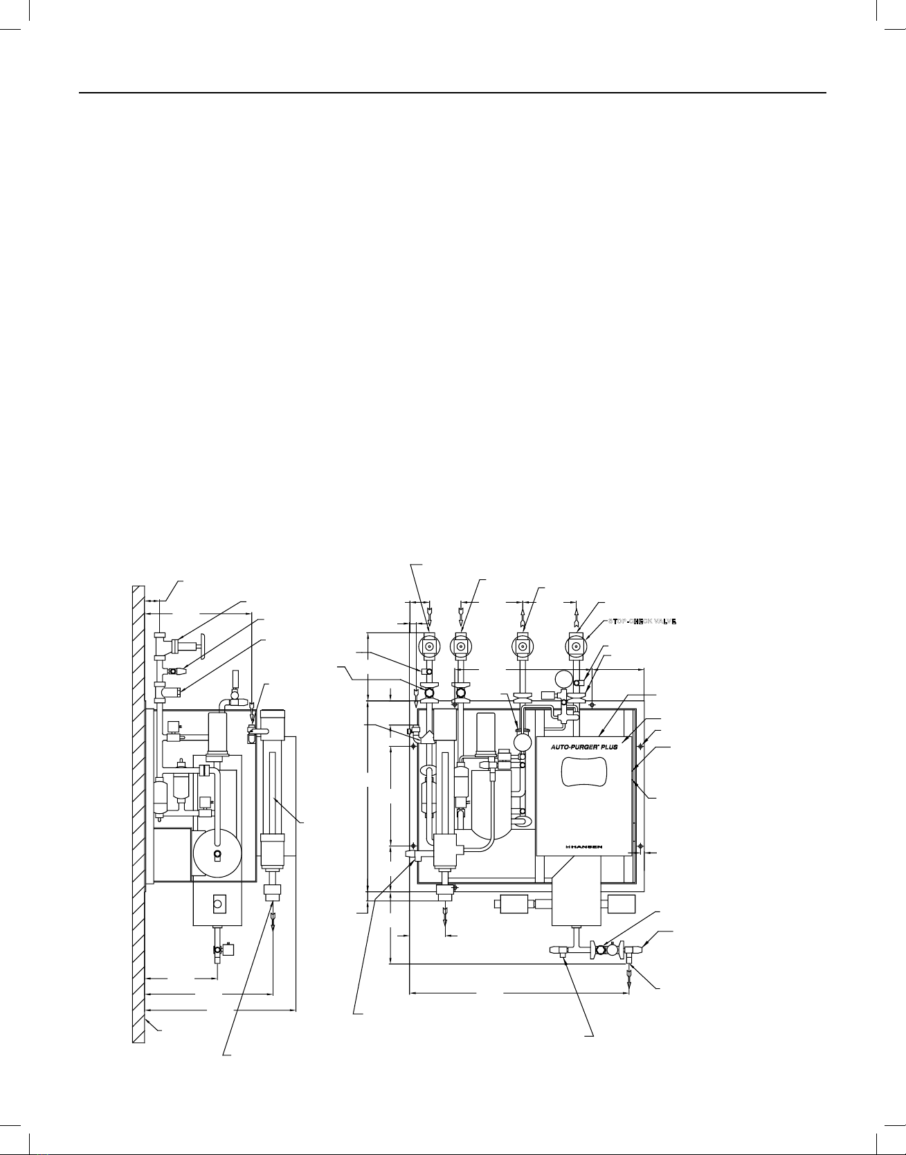
OIL DRAINS
Excess oil can reduce the purger capacity by lowering
the evaporating or condensing rate. Oil is not typically
a problem. Oil in the evaporator chamber is typically
released with the water that is released out the water purge
line. However, any oil that may collect in the purger can
be drained off through the two capped ¼” valves on the
purger, see Figure 1. Before draining oil, close the purge
gas gauge valve to the water bubbler, the low-pressure
pumped-liquid line shut-off valve, the foul gas line shut-
off valve, and the water bubbler fill line valve. Allow the
purger to pump out, then close the low-pressure liquid
return and suction line valves. Use normal oil draining
precautions to prevent injury or property damage.
ELECTRICAL CONNECTIONS
The standard AUTO-PURGER Plus requires a 115V 50/60Hz
17 amp electrical supply on a 20 amp circuit breaker;
models for 220V 50/60Hz, 11 amps electrical supply on
a 15 amp circuit breaker are available. All models have a
½” (13 mm) knockout on the side of the control cabinet to
access the power connection terminal strip.
AUTO-PURGER Plus models APPT08, APPT16, and APPT24
have an additional ¾” (20 mm) knockout for individual
purge point solenoid valves. Wires from each purge point
solenoid valve should be brought to the purger control
cabinet. Any additional access holes should be made on
the side of the control cabinet. All access holes into the
control cabinet must be sealed to prevent moisture, dust,
and debris entering the cabinet.
From each purge point solenoid, one wire is connected
to the corresponding screw terminal for the purge point
inside the control cabinet on the terminal strip. For 115V
models, the other wire from the purge point solenoid is
connected together for all the purge points and tied to
the available neutral position on the top terminal strip.
For the 220V models, the other wire from the purge point
solenoid is connected together for all the purge points
and tied to the top terminal strip labeled PP_COM. Both
115V and 220V models APPT08, APPT16, and APPT24
supply 115V to the purge points.
All APPT models have a relay available which energizes
whenever action is required by plant personnel. The
normally open contacts will close when action is required.
If desired, the contacts may be connected to a light, an
audible alarm, or to a plant computer, to notify plant
personnel to attend to the purger. The contacts are rated
for 10 amps. Connection to the relay is made at the top
terminal strip labeled REMOTE RELAY.
The purger should not be operated when the refrigeration
compressors are stopped. It is recommended to install
a customer supplied, externally mounted, power relay to
de-energize the purger when the refrigeration compressors
are stopped.
After completing all electrical connections inside the
cabinet, connect the cable from the Touchscreen to the
PLC. Connect the cable plug to the socket and tighten the
hand screws. Refer to the wiring tag inside unit.
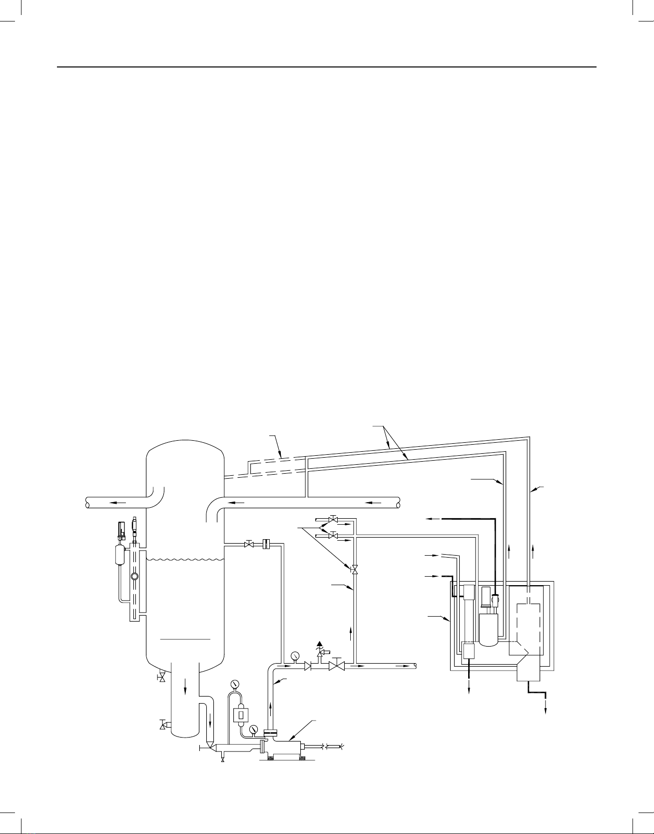
LEAK TEST
Use standard refrigeration procedures to check the
AUTO-PURGER Plus for leaks before placing it in service.
To confirm a leak-free AUTO-PURGER Plus, manually
open one remote purge point solenoid valve, if there is
one. Manually open the foul gas shut-off valve and allow
pressure inside the purger to build to condensing pressure,
as shown on the high side pressure gauge. Then, manually
open the high side to low side bypass valve to pressurize
the evaporator section of the purger, as shown on the low
side pressure gauge, see Figure 6. Check for leaks. Close
the high side to low side bypass valve.
SECTION 2 INSTALLATION

6
APP-001f
SEPT 2016
An indication of proper operation of the metering valve is
a frosted liquid feed line from the metering valve to the
low-pressure liquid-return line. If the line is not frosted
when the purger is in COLLECTING AIR/WATER mode, then
the flow of refrigerant through the line may be blocked
due to dirt in the metering valve or strainer.
The metering valve is set and held in place by a locking
knob. Unlock this knob using the .035” hex key wrench
provided inside the purger control cabinet. To clean the
orifice of the metering valve, fully open the metering
valve to flush out any particles. Then, close the valve and
reopen two turns.
If the line still does not frost, then pump out the purger
and inspect the strainer and metering valve.
HIGH SIDE TO LOW SIDE BYPASS VALVE
The High Side To Low Side Bypass Valve is normally
closed. The AUTO-PURGER Plus has portions that
normally contain high pressure, and portions that normally
contain low pressure. The two portions are separate and
isolated from each other. For some maintenance and
testing purposes, it may be desirable to connect the two
together so that the pressure in both is the same. The
High Side To Low Side Bypass Valve may be opened for
these purposes. Return this valve to its closed position
for normal operation, see Figure 5.
WATER BUBBLER
Noncondensible gas released from the AUTO-PURGER
Plus flows through the water bubbler where residual
ammonia is absorbed into the water. Large, 1” (25 mm)
diameter bubbles in the water bubbler indicate proper
operation. The water, with absorbed ammonia, flows to a
drain. The water bubbler fill line solenoid valve (D) opens
to automatically replenish water to the bubbler each time
the purge gas solenoid valve (C) energizes. The water
bubbler fill line solenoid valve (D) remains energized
for 30 seconds after the purge gas solenoid valve (C)
de-energizes (float switch magnet pulls in). This fills the
water bubbler with fresh water for the next purge cycle.
LIQUID DRAINER
The liquid drainer separates any liquid condensed in the
purge point piping. This liquid is fed to the low-pressure
liquid return line. Therefore, only foul gas—no liquid—
enters the condensing section of the purger. However,
if too much liquid comes down the foul gas line due to
improper piping, corrective action must be taken.
VAPOR TRAP
The vapor trap separates any vapor that flashes in the
low-pressure pumped liquid line piping. This vapor is
fed to the suction line. Therefore, only liquid—no vapor—
flows through the liquid make-up solenoid valve (B) to the
evaporator chamber of the purger.
CHECK VALVES
There are five check valves on the purger.
a) 1 psid (.07 bar) check valve with a 1/32” (.8 mm) diameter
metering orifice is installed on the purge gas line to
prevent reverse flow of water into the purger from the
water bubbler.
b) 225 psid (15.5 bar) relief check valve from the float
chamber to suction line.
c) 1 psid (.07 bar) relief check valve from the suction line
to the float chamber.
d) 1 psid (.07 bar) check valve in the water purge line to
prevent reverse flow of water into the purger from the
customer supplied container.
e)The water bubbler fill line has a ½” check valve.
PURGE GAS ORIFICE
A metering orifice disc is installed inside the 1 psid (0.07
bar) check valve in the purge gas line to the water bubbler,
see Figure 6. This 1/32” (0.8 mm) diameter orifice meters
the noncondensible gas into the water bubbler to prevent
over or under feeding. The ¼” NPT gauge valve should
be fully open during operation and closed for pump out
or maintenance.
METERING VALVE
The metering valve meters condensed liquid refrigerant
from the high-pressure float switch chamber of the purger
into the low-pressure liquid-return line. The refrigerant
is filtered through a small flanged strainer prior to the
metering valve, which removes any particles that might
block the orifice.
PURGE GAS SOLENOID VALVE
Figure 4
1/4" PURGE GAS GAUGE VALVE
WIDE OPEN DURING OPERATION
CLOSED FOR SERVICING PURGER
PURGE GAS
1/32" (0.8 MM) DIA
METERING ORIFICE
(0.07 BAR)
PURGE GAS TO WATER BUBBLER OR
TO CUSTOMER SUPPLIED WATER BOTTLE
CHECK
VALVE
SOLENOID VALVE
DISC INSTALLED IN
THE CHECK VALVE
1 PSID
SECTION 3 COMPONENT DESCRIPTIONS

7
APP-001f
SEPT 2016
TEMPERATURE SENSORS
There are three temperature sensors on the purger. All
three temperature sensors are type J thermocouples.
a)The evaporator shell temperature sensor is mounted
to the outside of the evaporator shell, and controls
the 3333 EVAP TEMP> 40F (4C) indication. It may be
replaced without pumping-out the purger.
b)The plate heater temperature sensor is mounted in
the bottom plate of the evaporator shell, between the
two electric heaters. It is used to control the heaters
to maintain adequate temperature of the plate when
CONCENTRATING WATER. It may be replaced without
pumping-out the purger, but may be very hot if the
heaters are energized.
c)The liquid temperature sensor measures the temperature
of the liquid inside the evaporator. It is used to indicate
liquid temperature when CONCENTRATING WATER. It
also is used to end the CONCENTRATING WATER cycle
and indicate READY TO DRAIN when the water has
reached the desired temperature. The purger must be
pumped-out to replace it because it is in direct contact
with the ammonia/water solution.
PRESSURE TRANSDUCERS
There are two pressure transducers on the purger. Each
provides a 4-20 mA output proportional to pressure from
30 in-Hg to 285 psig (-1.0 bar to +19.7 bar).
a)The low side pressure transducer measures the pressure
in the evaporator shell. It is used to adjust the set point
temperature to which the ammonia/water solution is
heated if the suction is operating in a vacuum, which
prevents boiling off the water. It also controls the
low-side pressure-assist solenoid valve (F) to maintain
positive pressure for draining water if the suction is in
a vacuum.
b)The high side pressure transducer measures the pressure
in the air separator chamber. It controls the 2222 FOUL
GAS<80 PSI (5 BAR) indication, which prevents the purge
gas solenoid valve (C) from energizing if the purger has
insufficient pressure.
SINGLE POINT LEVEL SENSORS
There are two single point level sensors on the purger,
which operate on the principle of capacitance to determine
whether liquid or gas is present. The level sensor has
a relay contact which is open when the sensor is in gas,
and which closes when the sensor is in liquid ammonia.
Further information may be found in bulletin P105.
a)The liquid make-up level sensor controls the low-
pressure pumped-liquid solenoid valve (B) to maintain
the ammonia level in the evaporator shell.
b)The low liquid level sensor prevents the electric heaters
from energizing if no liquid is present, which protects
the heaters from damage. It also controls the water
purge line solenoid valve (G) while draining water. While
water is draining, the water purge line solenoid valve
(G) will remain energized for 10 seconds after the low
liquid level sensor goes dry, and then will shut.
WATER CONCENTRATION SENSOR
The water concentration sensor measures temperature
and pressure in a single sensor, compares the two, and
outputs a 4-20 mA signal of the water concentration. A
current of 12 mA or less indicates no water. Each mA
above 12 mA is equivalent to 7.5% water concentration.
For example, 13 mA indicates 7.5% water, 14 mA indicates
15% water, and 15 mA indicates 22.5% water.
The maximum range for the water concentration sensor is
20 mA which indicates 60% water. Any water concentration
above 60% is out of range. The APPT display will only
indicate a maximum of 60% water, even if the concentration
is greater than 60%.
The water concentration sensor will only provide an
accurate reading when immersed in liquid. For example,
when the APPT is pumped-out, the water concentration
sensor will indicate 60%, because it senses low pressure
(1 atmosphere) and warm temperature (room temperature),
which would mean a high concentration of water if it were
sensing a liquid ammonia/water solution.
ELECTRIC HEATERS
The APPT has two electric heaters, which are used during
the CONCENTRATING WATER mode. When the purger is
CONCENTRATING WATER, the ammonia/water solution
is heated to evaporate as much ammonia as possible, so
that when the water is released it has as little ammonia
as possible. Each heater is 750 W.
PURGE POINT SOLENOID VALVES
For the customer-supplied purge point solenoid valves,
Hansen recommends our HS8A with close-coupled strainer.
This is a 1/2” port, heavy-duty, pilot-operated solenoid
valve with stainless steel piston. The purge point solenoid
valve must be a minimum of 1/2” port size to avoid excess
pressure drop across the valve.
The standard molded coil is for 115V, (208/230V or 24V
are available). Flange connections available are 1/2”,
3/4”, and 3/8” FPT, socket weld, and weld neck. To order,
specify catalog number HS8A with close coupled strainer,
required connection style and size, and volts. Specify DIN
plug solenoid connection if needed.
Both 115V and 220V models APPT08, APPT16, and APPT24
supply 115V to the purge points.
SECTION 3 COMPONENT DESCRIPTIONS

8
APP-001f
SEPT 2016
SECTION 3 COMPONENT DESCRIPTIONS
TOUCHSCREEN
The Touchscreen is the operator’s interface with the
APPT software. The Touchscreen display has two display
modes, the Menu Display Mode and the Status Display
Mode. The Status Display Mode will indicate the operating
conditions and alert the operator of the inputs to the APPT.
This is the display mode the APPT will most likely operate
in. In the Menu Display Mode the operator can verify
and in some cases change various system parameters,
troubleshoot their APPT, or remove their data storage
device. To switch between the two display modes press
“ESC” on Touchscreen.
There are four navigation keys on the Touchscreen:
ESC – Switch between the status mode and menu mode,
also used to exit back through menu mode.
/\ - Navigate up
\/ - Navigate down
ENTER – To enter a specific menu hierarchy or enter a
parameter change
ESC
/\
\/
ENTER
Auto-PurgerPlusTechnologyPackageColorTouchscreen
OK
STATUS
RESET4444
PURGEPOINTADV
Along the bottom of the control console there are four functional keys for specific tasks. Each will have a green dot
above it when the key is available and a red dot above it when the key is unavailable.
OK – This key will become active when the purger is ready
to drain water following water concentration mode. It will
need to be pressed when prompted to open the water
purge solenoid and again when prompted to close the
water purge solenoid.
STATUS – Pressing this key will display the status screens
of the operating conditions of the APPT (there are eight
status screens; see below).
RESET 4444 – Reset 4444 alarm condition (see Section
7 Troubleshooting for explanation of alarm).
PURGE POINT ADV – This key is pressed to manually
advance to the next purge point (key not applicable on
APP(T)C model).
5

9
APP-001f
SEPT 2016
SECTION 3 COMPONENT DESCRIPTIONS
MENUSCREENSFORAPPT
AirPurgeLimit
PurgePointEnable
WaterCollecJon
DisplayUnits
MenuScreen1
Air Purge Limit – APPT can limit the amount on continuous
air purge time to 60 minutes during normal operation. If
there are large amounts of noncondensibles expected to
be present, for example during startup, this limit can be
disabled allowing the APPT to purge air continuously. To
change the selection, press /\ or \/ to enable or disable.
Purge Point Enable – APPT08 has purge points 01-08,
APPT16 has purge points 01-16, and APPT24 has purge
points 01-24. At system startup, when a purger is initially
installed in a system having fewer purge points than are
available on the APPT, the unused purge points must be
set to 0. To enable or skip a purge point simply touch
the purge point button on the screen and it will change
the selection.
Water Collection – This screen contains information
that can’t be changed. The counts indicate the time (in
seconds) the water concentration as measured by the
water concentration sensor (HPT717) exceeds the water
concentration set point. The concentration of water in the
purger evaporator must exceed 25% for 10 continuous
minutes AND have the low liquid level sensor reading wet
before the purger will enter Concentrating Water mode.
Drain Mode will always read 0 and can’t be changed.
Display Units – Changes the temperature and pressure
units for the display readout. To change the selection,
press /\ or \/ to switch the units.
MENU SCREENS FOR APPT

10
APP-001f
SEPT 2016
SECTION 3 COMPONENT DESCRIPTIONS
Version
Language
AlarmHistory
SetupScreen
MenuScreen2
Version – This menu contains information which can’t be
changed. This will provide the programming version of
both the APPT’s internal PLC and touchscreen.
Language – Allows the user to change the language of
the APPT menus and readouts.
Alarm History – This menu contains information which
can’t be changed. This menu provides a list of all the error
codes with the date and time the code appeared. Codes
will appear on this list even if they are self-correcting,
meaning the operator didn’t need to make corrections to
APPT to solve error code.
Setup Screen – Factory configured set-up parameters.
Consult Hansen prior to attempting to change parameters.
MENU SCREENS–CONTINUED

11
APP-001f
SEPT 2016
SECTION 3 COMPONENT DESCRIPTIONS
Troubleshooting Help –This menu allows the user to
scroll through the error code messages for the APPT and
read the meaning of the error code and possible causes
and solutions to the error code.
Data Acquisition – This screen allows the user to disable
data collection of the APPT or remove the storage device
for user review. All APPT manufactured after October 1,
2016 contain the ability for the touchscreen to record
operating data from the purger and store it on a USB
storage device or SD card. To download these Excel
spreadsheets the storage device must be removed from
the APPT touchscreen and plugged into a computer.
System Reset – Resets the APPT system similar to
rebooting a computer. This will clear any error codes
except Service Required, clear the purge counts for air
and water, and temporarily stop purging air or water during
operation. This will not reset the parameters purge point
enabled/disable, air purge time limit, HMI Display, and
display units. If this key is pressed while liquid level make
up sensor is reading on/wet, the APPT will go into System
Initialize mode until the sensor reads dry/off and then the
APPT will proceed with standard operation.
HMI Display – The PLC is programmed to work with the
obsolete keypad and monochrome touchscreen, as well
as the color touchscreen but the touchscreen must be
set to HMI Display.
!
! ! ! !
Troubleshoo*ngHelp–Thismenuallowstheuserto
scrollthroughtheerrorcodemessagesfortheAPPT
andreadthemeaningoftheerrorcodeandpossible
causesandsolu:onstotheerrorcode.
DataAcquisi*on–Thisscreenallowstheuserto
disabledatacollec:onoftheAPPTorremovethe
storagedeviceforuserreview.AllAPPTmanufactured
a=erOctober1,2016containtheabilityforthe
touchscreentorecordopera:ngdatafromthepurger
andstoreitonaUSBstoragedeviceorSDcard.To
downloadtheseExcelspreadsheetsthestorage
devicemustberemovedfromtheAPPTtouchscreen
andpluggedintoacomputer.
SystemReset–ResetstheAPPTsystemsimilarto
reboo:ngacomputer.Thiswillclearanyerrorcodes
exceptServiceRequired,clearthepurgecountsforair
andwater,andtemporarilystoppurgingairorwater
duringopera:on.Thiswillnotresettheparameters
purgepointenabled/disable,airpurge:melimit,HMI
Display,anddisplayunits.Ifthiskeyispressedwhile
liquidlevelmakeupsensorisreadingon/wet,the
APPTwillgointoSystemIni:alizemodeun:lthe
sensorreadsdry/offandthentheAPPTwillproceed
withstandardopera:on.
HMIDisplay–ThePLCisprogrammedtoworkwith
theobsoletekeypad,monochrometouchscreen,as
wellasthecolortouchscreenbutthetouchscreen
mustbesettoHMIDisplay.
MenuScreen3
Troubleshoo:ngHelp DataAcquisi:on SystemReset HMIDisplay
MENU SCREENS–CONTINUED

12
APP-001f
SEPT 2016
O
StatusScreen4willprovidethehighsideandlowsidepressureasrecordedfromthepressuretransducers.
O
StatusScreen5willtellwhichAPPTsolenoidsareenergized.Thisscreenshouldmatchthebeaconlightsbeingon/
offonthesolenoids(thisscreendoesn’tshowpurgepointsolenoids).
O
StatusScreen6willtelliftheheaterisenergized,thestartupdelaycounter,andconcentra>ngwaterreading.The
concentra>ngwaterreadingisarawnumberneedingtobeconvertedtogivetheWaterConcentra>onpercentage.
StatusScreen4
StatusScreen5
StatusScreen6
O
StatusScreen4willprovidethehighsideandlowsidepressureasrecordedfromthepressuretransducers.
O
StatusScreen5willtellwhichAPPTsolenoidsareenergized.Thisscreenshouldmatchthebeaconlightsbeingon/
offonthesolenoids(thisscreendoesn’tshowpurgepointsolenoids).
O
StatusScreen6willtelliftheheaterisenergized,thestartupdelaycounter,andconcentra>ngwaterreading.The
concentra>ngwaterreadingisarawnumberneedingtobeconvertedtogivetheWaterConcentra>onpercentage.
StatusScreen4
StatusScreen5
StatusScreen6
SECTION 3 COMPONENT DESCRIPTIONS
STATUSSCREENSFORAPPT
O
Statusscreen1willprovidethenumberof>mesthepurgerwentintoapurgecycleandreleasedeitherairorwater
andtheamountofminutesitspentduringthosepurges.
O
Statusscreen2willprovidethewaterconcentra>onmeasurementforthefloodedevaporatorchamberoftheAPPT.
Whenthefloodedevaporatorchamberisemptythisreadingwillbe60%.Thisvaluewillnotappearwhen
concentra>ngwatermodeisineffect.
O
Statusscreen3willprovidethetemperaturesthethermocouplesontheAPPTarereading.Theunitsdisplayedwill
matchwhatisselectedinMenuScreen1–DisplayUnits.
StatusScreen1
StatusScreen2
StatusScreen3
Status screen 1 will provide the number of times the purger went into a purge cycle and released either air or water and
the amount of minutes it spent during those purges.
Status screen 3 will provide the temperatures the thermocouples on the APPT are reading. The units displayed will
match what is selected in Menu Screen 1 – Display Units.
Status screen 2 will provide the water concentration measurement for the flooded evaporator chamber of the APPT.
When the flooded evaporator chamber is empty this reading will be 60%. This value will not appear when concentrating
water mode is in effect.
STATUS SCREENS FOR APPT

13
APP-001f
SEPT 2016
SECTION 3 COMPONENT DESCRIPTIONS
Status Screen 4 will provide the high side and low side pressure as recorded from the pressure transducers.
Status Screen 6 will tell if the heater is energized, the start up delay counter, and concentrating water reading. The
concentrating water reading is a raw number needing to be converted to give the Water Concentration percentage.
Status Screen 5 will tell which APPT solenoids are energized. This screen should match the beacon lights being on/off
on the solenoids (this screen doesn’t show purge point solenoids).
O
StatusScreen4willprovidethehighsideandlowsidepressureasrecordedfromthepressuretransducers.
O
StatusScreen5willtellwhichAPPTsolenoidsareenergized.Thisscreenshouldmatchthebeaconlightsbeingon/
offonthesolenoids(thisscreendoesn’tshowpurgepointsolenoids).
O
StatusScreen6willtelliftheheaterisenergized,thestartupdelaycounter,andconcentra>ngwaterreading.The
concentra>ngwaterreadingisarawnumberneedingtobeconvertedtogivetheWaterConcentra>onpercentage.
StatusScreen4
StatusScreen5
StatusScreen6
O
StatusScreen4willprovidethehighsideandlowsidepressureasrecordedfromthepressuretransducers.
O
StatusScreen5willtellwhichAPPTsolenoidsareenergized.Thisscreenshouldmatchthebeaconlightsbeingon/
offonthesolenoids(thisscreendoesn’tshowpurgepointsolenoids).
O
StatusScreen6willtelliftheheaterisenergized,thestartupdelaycounter,andconcentra>ngwaterreading.The
concentra>ngwaterreadingisarawnumberneedingtobeconvertedtogivetheWaterConcentra>onpercentage.
StatusScreen4
StatusScreen5
StatusScreen6
STATUS SCREENS–CONTINUED
STATUSSCREENSFORAPPT
O
Statusscreen1willprovidethenumberof>mesthepurgerwentintoapurgecycleandreleasedeitherairorwater
andtheamountofminutesitspentduringthosepurges.
O
Statusscreen2willprovidethewaterconcentra>onmeasurementforthefloodedevaporatorchamberoftheAPPT.
Whenthefloodedevaporatorchamberisemptythisreadingwillbe60%.Thisvaluewillnotappearwhen
concentra>ngwatermodeisineffect.
O
Statusscreen3willprovidethetemperaturesthethermocouplesontheAPPTarereading.Theunitsdisplayedwill
matchwhatisselectedinMenuScreen1–DisplayUnits.
StatusScreen1
StatusScreen2
StatusScreen3

14
APP-001f
SEPT 2016
SECTION 3 COMPONENT DESCRIPTIONS
Status Screen 7 provides the state of the level sensors and the float switch.
Status Screen 8 will provide the operating mode the purger is in and the active purge point (not applicable for APPC
model)
O
StatusScreen7providesthestateofthelevelsensorsandthefloatswitch.
O
StatusScreen8willprovidetheopera>ngmodethepurgerisinandtheac>vepurgepoint(notapplicableforAPPC
model)
StatusScreen7
StatusScreen8
O
StatusScreen7providesthestateofthelevelsensorsandthefloatswitch.
O
StatusScreen8willprovidetheopera>ngmodethepurgerisinandtheac>vepurgepoint(notapplicableforAPPC
model)
StatusScreen7
StatusScreen8
STATUS SCREENS–CONTINUED

15
APP-001f
SEPT 2016
SECTION 3 COMPONENT DESCRIPTIONS
DISPLAYMESSAGES
StartupDelayMode
SystemIniJalizing
ReleasingAir
CollecJngAir/Water
DISPLAYMESSAGES
StartupDelayMode
SystemIniJalizing
ReleasingAir
CollecJngAir/Water
DISPLAYMESSAGES
StartupDelayMode
SystemIniJalizing
ReleasingAir
CollecJngAir/Water
DISPLAYMESSAGES
StartupDelayMode
SystemIniJalizing
ReleasingAir
CollecJngAir/Water
Startup Delay Mode – appears for 10 minutes after APPT
evaporator shell temperature reads below 40F (4C) and
the foul gas pressure is higher than 80 PSIG (5.5 BARG).
System Initializing – appears after either the System
Reset key has been pressed or power is cycled to the
APPT while the Liquid Make-Up Level Sensor is reading
wet. APPT will stay in this mode until Liquid make-Up
Level Sensor reads dry. This prevents the heaters from
turning on until the evaporator shell has filled with liquid.
Collecting Air/Water – appears when the APPT is in
its normal operating of collecting noncondensible gas
and water.
Releasing Air – appears when the APPT is releasing
noncondensible gas.
DISPLAY MESSAGES FOR APPT

16
APP-001f
SEPT 2016
SECTION 3 COMPONENT DESCRIPTIONS
O
ConcentraJngWater–appearsduringtheprocessof
hea>ngtheammonia/watersolu>ontoremoveas
muchammoniafromthewateraspossiblebefore
releasingthewater.Theliquidtemperatureappears
duringtheconcentra>ngwatermodetoindicatethe
temperatureoftheammonia/watersolu>on(units
willmatchtheselecteddisplayunits).
O
READYTODRAINWATER.OPENWATERPURGE
SHUT-OFFVALVETHENPRESSOKKEY–appears
whentheconcentra>ngwaterprocesshasbeen
completedandwaterisreadytobedrained.
O
DrainingWater–appearswhentheconcentrated
waterisdrainingfromtheAPPT.
O
DRAININGCOMPLETE.CLOSEWATERPURGESHUT-
OFFVALVETHENPRESSOKKEY–appearswhenthe
APPTisdonedrainingandisreadytogobacktoits
normalmode,Collec>ngAir/Water
O
ConcentraJngWater–appearsduringtheprocessof
hea>ngtheammonia/watersolu>ontoremoveas
muchammoniafromthewateraspossiblebefore
releasingthewater.Theliquidtemperatureappears
duringtheconcentra>ngwatermodetoindicatethe
temperatureoftheammonia/watersolu>on(units
willmatchtheselecteddisplayunits).
O
READYTODRAINWATER.OPENWATERPURGE
SHUT-OFFVALVETHENPRESSOKKEY–appears
whentheconcentra>ngwaterprocesshasbeen
completedandwaterisreadytobedrained.
O
DrainingWater–appearswhentheconcentrated
waterisdrainingfromtheAPPT.
O
DRAININGCOMPLETE.CLOSEWATERPURGESHUT-
OFFVALVETHENPRESSOKKEY–appearswhenthe
APPTisdonedrainingandisreadytogobacktoits
normalmode,Collec>ngAir/Water
Concentrating Water Mode – appears during the process
of heating the ammonia/water solution to remove as much
ammonia from the water as possible before releasing
the water. The liquid temperature appears during the
concentrating water mode to indicate the temperature of
the ammonia/water solution (units will match the selected
display units).
Ready to Drain Water – appears when the concentrating
water process has been completed and water is ready to
be drained.
Draining Complete – appears when the APPT is done
draining and is ready to go back to its normal mode,
Collecting Air/Water
Draining Water – appears when the concentrated water
is draining from the APPT.
DISPLAY MESSAGES–CONTINUED

17
APP-001f
SEPT 2016
SECTION 3 COMPONENT DESCRIPTIONS
TOUCHSCREEN DATA ACQUISITION
The APPT features data collection which is activated by
default on start up of the APPT, unless the user manually
deactivates or does not have a storage device plugged
into the touch panel. Two files will be created, DATA.csv
and MODE.csv. The data will be saved on the flashdrive
by default but there is also the option of using a micro SD
card. Whichever of these storage devices are used, they
must be in FAT or FAT32 format. It is recommended to
use a 2G or less storage device in order to limit the size
of the files so they can be easily opened and reviewed.
It is recommended to either download and/or delete the
files from the storage device after 8 months. The data
will stop writing to the file once the memory device is full
(notification will not be given prior to data writing stopping).
The DATA file is recorded every minute and contains the
status of the float switch, liquid make-up level sensor, low
liquid level sensor, liquid temperature, plate temperature,
shell temperature, low side pressure sensor, high side
pressure sensor, water concentration sensor, and the
state of the solenoids on the APPT. Each line will also
have a date and time stamp as well as indicating if there
is any error code at that time.
The MODE file is recorded every two minutes and it contains
the mode the purger is in at that time. The conditions
recorded are Satisfied (normal operation, collection air/
water), Cool Down, A_OP, and Water Concentration.
The data acquisition feature can be disabled if the user
so desires. Going to Menu Screen 3 and selecting Data
Acquisition, you come to the button to enable/disable
the data collection feature. Pressing DAQ ENABLED will
change the button to read DAQ DISABLED which turns
off the data collection.
DATAACQUISITION
Note: Selecting DAQ Enabled will stop the APPT from collecting
and saving the data to your storage device. To remove the storage
device, press the Remove Storage Device button. When the dot
turns green, remove your flashdrive/SD card. The touchscreen
will not record or store any data while the dot is green or when
the top button reads DAQ Disabled.
Note: When looking at the back of the Touchscreen, the USB
port is at the top left and the SD Card port is at the bottom right.
If there is both a USB and SD card installed in the Touchscreen,
only the USB will record data.
TOUCHSCREENDATAACQUISITION
/
Note:
Note

18
APP-001f
SEPT 2016
SECTION 3 COMPONENT DESCRIPTIONS
TOUCHSCREEN TROUBLESHOOTING GUIDE
On the touchscreen of the APPT there is a built-in
troubleshooting guide. This guide will show all the error
messages displayed, what the error condition is, and a few
conditions to check to fix the error state. This guide can
be accessed in two ways, Menu Screen 3 has an option
for Troubleshooting Help. Pressing this option will bring
you to the menu below where you can select which error
condition you are looking for.
TROUBLESHOOTINGGUIDE
Note: The second way to access this guide is when you are in an error state there will be a button which will appear. Pressing that
button which coincides with the error state the APPT currently is in will bring up the troubleshooting section for that particular error.
The guide programmed into the touchscreen is the same guide which is following this section in the product bulletin.

19
APP-001f
SEPT 2016
OPERATION
After the 10 minute STARTUP DELAY MODE is complete,
the purger will enter its normal mode of COLLECTING
AIR/WATER.
The foul gas that flows into the purger may carry a certain
amount of condensed refrigerant, which is captured by
the liquid drainer before it enters the purger’s condenser
coil. From the liquid drainer, the liquid is fed directly into
the low-pressure liquid return line. If this separation does
not occur, liquid refrigerant will fill the purger’s condenser
and limit the condensing capacity of the purger.
The liquid-free foul gas enters the purger condensing
coil, which is submerged in the flooded evaporator. The
refrigerant condenses inside the coil. The condensed
refrigerant and noncondensible gas then flow through
a check valve and into the air separator chamber. The
condensed liquid refrigerant is removed from the high-
pressure air separator chamber through the liquid metering
valve and to the low-pressure liquid return line.
Meanwhile, the noncondensible gas travels along the
top of the air separator chamber and into the float ball
chamber where it collects. As more noncondensible gases
collect, the liquid level gradually falls, causing the float
ball to fall. This changes the SPDT switch position of
the liquid level float switch and energizes the purge gas
solenoid valve (C) and the water bubbler fill line solenoid
valve (D), allowing noncondensible gas to bleed through
the orifice plate into the water bubbler. The Touchscreen
indicates RELEASING AIR. As air is released into the
water bubbler, the liquid refrigerant level in the purger
float ball chamber rises.
The control software operates each enabled remote
purge point solenoid valve in sequence. The control
software energizes each purge point for 10 minutes. If
noncondensibles are released during this 10 minute period,
then the control software will remain on that particular
purge point for 10 additional minutes, for a total of 20
minutes. If noncondensibles are released during this
second 10 minute period, then the control software will
remain on that particular purge point for another 10 minutes,
for a total of 30 minutes. After a total of 30 minutes on one
particular purge point, the control software will move to the
next purge point, regardless of whether noncondensibles
were released in the third 10 minute period.
The make-up liquid from the low-pressure pumped
liquid line typically contains a small percentage of water
dissolved in the liquid ammonia. This is the water the AUTO-
PURGER Plus will remove from the refrigeration system.
Liquid ammonia and water are brought into the evaporator
chamber of the purger, where the ammonia is evaporated
and the water remains. Gradually the concentration of water
in the evaporator chamber increases with time. When the
concentration of water in the evaporator chamber reaches
about 25% water for 10 continuous minutes, as detected
by the water concentration sensor, the AUTO-PURGER
Plus switches to the CONCENTRATING WATER mode. The
purger stops collecting air, isolates the mixture of water
and ammonia, and energizes the two electric heaters.
SECTION 4 AUTO-PURGER PLUS OPERATION
The AUTO-PURGER Plus is designed to automatically
startup and operate without the assistance of plant
personnel. Beginning at start-up, the following is a
description of the refrigerant flow through a purger when
all connecting shut-off valves are open, see Figure 6.
START-UP
Make sure all piping, electrical connections, and settings
are complete as described in this bulletin.
Models APPT08, APPT16, and APPT24 should have unused
purge points disabled before start-up. For example, an
APPT08 that will only use 6 of the possible 8 purge points,
should have purge points 7 and 8 disabled in the purger
software. All purge points are enabled when shipped
from the factory. To disable purge point, first energize the
purger. Press the ‘Purge Point Enable’ button on Menu
Screen 1. Then, touch the button of the purge point on the
screen you wish to disable. If purge point is not shown
on the screen, scroll up or down with \/ or /\ button to
get to the purge point to disable and touch that button
on the screen.
To start-up the APPT, open the foul gas, low-pressure
pumped-liquid, low-pressure liquid return, and suction
line shut-off valves. Open the purge gas valve. The water
purge line shut-off valve should remain closed at this
time (open only while draining water), see Figure 6. On
start-up, the AUTO-PURGER Plus enters a cooling down
stage. The display indicates 3333 EVAP TEMP >40F (4C).
In this stage, liquid refrigerant fills and cools the purger.
The low-pressure pumped-liquid line solenoid valve (B)
energizes to feed refrigerant to the low-pressure flooded
evaporator. The liquid make-up level sensor, located in the
evaporator chamber, senses when the flooded evaporator
is full and closes the low-pressure pumped-liquid line
solenoid valve (B).
At the same time the flooded evaporator is cooling, the
control software energizes the first purge point solenoid
valve. Foul gas enters the high-pressure air separator
chamber and condenses to fill the high-pressure air
separator chamber with liquid ammonia. When the float
switch chamber fills with liquid refrigerant, the float ball
rises and pulls in the float switch magnet. (If this chamber
is already full of air, the float switch magnet will not pull-in
until later when this air is released to the bubbler.)
After the evaporator shell temperature has cooled below
40°F, the purger switches from the cooling down stage to
STARTUP DELAY MODE for 10 minutes, as indicated by the
Touchscreen no longer displaying 3333 EVAP TEMP>40F
(4C), but instead displaying STARTUP DELAY MODE. The
control software will not allow any noncondensibles to
be released into the water bubbler until the 10 minute
STARTUP DELAY MODE is complete. This 10 minute delay
is necessary to give the purger time to condense enough
foul gas to fill the high pressure air separator chamber
with liquid ammonia.
continued on page 21
TROUBLESHOOTINGGUIDE

20
APP-001f
SEPT 2016
AUTO-PURGER PLUS APPT FLOW DIAGRAM
Figure 6
1" WATER BUBBLER
WATER
BUBBLER
OVERFLOW
TUBE
½" FOUL
GAS LINE
½" LOW-PRESSURE
PUMPED-LIQUID LINE ¾" SUCTION LINE
FILL LINE
D
B
C
FLOW REGULATOR
GAUGE VALVE
GAUGE VALVE
LIQUID MAKE-UP
LEVEL SENSOR
CHECK VALVE
LIQUID
DRAINER
OIL DRAIN AND PUMP OUT
HIGH PRESSURE
EVAPORATOR SHELL
FLOAT
SWITCH
1 PSID (0.07 BAR)
CHECK VALVE
½" LOW-PRESSURE
LIQUID RETURN LINE
STOP/CHECK VALVE
METERING
VALVE
HIGH SIDE PRESSURE TRANSDUCER
LEVEL SENSOR
LOW LIQUID
WATER CONCENTRATION SENSOR
ELECTRIC HEATERS
VAPOR
TRAP
TEMPERATURE SENSOR
PLATE HEATER TEMPERATURE SENSOR
LIQUID TEMPERATURE SENSOR
225 PSID (15.5 BAR) RELIEF CHECK VALVE
LOW SIDE PRESSURE TRANSDUCER
STRAINER
E
F
G
1 PSID (0.07 BAR) CHECK VALVE
AIR SEPARATOR
N.C.
OIL DRAIN AND PUMP OUT
FLOODED EVAPORATOR CHAMBER
1 PSID (0.07 BAR) RELIEF CHECK VALVE
WATER PURGE LINE
TO CUSTOMER SUPPLIED CONTAINER
GAS
RELIEF VALVE
300 PSI (20.7 BAR)
½" WATER BUBBLER
DRAIN LINE TO SEWER
RELIEF VALVE
VENT LINE
SOLENOID VALVES:
BLOW-PRESSURE PUMPED-LIQUID SOLENOID VALVE
CPURGE GAS SOLENOID VALVE
DWATER BUBBLER FILL LINE SOLENOID VALVE
ESUCTION LINE SOLENOID VALVE
FLOW-SIDE PRESSURE-ASSIST SOLENOID VALVE
GWATER PURGE LINE SOLENOID VALVE
ASSEMBLY
CHAMBER
HIGH SIDE TO LOW SIDE
BYPASS VALVE
(NORMALLY CLOSED)
WITH ORIFICE
PURGE
VALVE
WATER PURGE LINE
SHUT-OFF VALVE
NO ORIFICE
WATER PURGE LINE STRAINER
NO ORIFICE
1
SECTION 4 AUTO-PURGER PLUS OPERATION
This manual suits for next models
3
Other Hansen Industrial Equipment manuals
Popular Industrial Equipment manuals by other brands

Stanley
Stanley 71502 Instruction and service manual

Gorlitz
Gorlitz GO 4000 Operating & maintenance instructions

Emerson
Emerson Liebert iCOM manual

Electro Scan
Electro Scan EST12 Installation and maintenance instructions

Tronair
Tronair 06-5042 Series Operation & service manual

Rockwell Automation
Rockwell Automation THR Triguard SC300E quick start guide