Diamond Audio DES Series User manual
DES SeriesDES Series
DIGITAL AMPLIFIERSDIGITAL AMPLIFIERS
DES400.2D/DES400.4D/DES500.1D
DES1000.1D/DES1000.5D
DES400.2D/DES400.4D/DES500.1D
DES1000.1D/DES1000.5D

INTRODUCTION
2
Congratulations, you have just purchased one of the finest mobile audio products on the
market. Diamond Audio products represent the latest advances in acoustic technology in
sound reproduction for your vehicle. Diamond Audio products are designed, developed, and
engineered in the USA using the latest innovative materials and components to provide the
finest sound reproduction possible. Every Diamond Audio product has been verified and
tested to ensure the best sounding and most reliable product on the market, if installed
properly. Diamond Audio products will provide many years of the ultimate listening experience.
Please note that prolonged exposure to sound pressure levels in excess of 100dB can cause
permanent hearing loss. Using Diamond Audio products can exceed that level, so please
exercise restraint in its operation in order to preserve your ability to enjoy its high fidelity sound
for many years to come.
Diamond Audio recommends our products be professionally installed by an authorized
Diamond Audio dealer to achieve the best possible system recommendation and installation.
This will ensure a true Diamond Audio listening experience and sound you would expect from
Diamond Audio products. With proper validation use a Diamond Audio Retailer for installation
of your newly purchased amplifier. Diamond Audio will extend the product warranty from one
year to Two Years!!
Go ahead, Hear the Music

3
INSTALLATION -Pre Planning Section
WARNING:
Prolonged exposure to sound pressure levels in excess of 100dB can cause permanent hearing loss.
Diamond Audio amplifiers can exceed that level so please exercise restraint when listening and enjoying your new amplifier.
GENERAL PRECAUTIONS
• This unit is designed for negative ground 12V DC operation only.
• Total system impedance must not be less than 2ohms, in a bridged OR stereo configuration
• Avoid installing the unit where:
- It would be subject to high temperatures, such as from direct sunlight or hot air from the heater.
- It would be exposed to rain or moisture.
- It would be subject to dust or dirt.
• Do not cover the unit with carpet or wires.
• Do not use the unit with a weak vehicle battery. Optimum performance depends on a normal battery supply voltage.
• For safety reasons, keep the volume of your vehicle audio system moderate while driving. This is so you can still hear
normal traffic sounds outside your car.
• There is NO speaker level input connector, you can cut RCA’s and solder the wires and connect directly thru the RCA input.
MOUNTING PRECAUTIONS
Although Diamond Audio amplifiers incorporate heat sinks and protection circuits, mounting the amplifier in a tight space
without any air movement can still damage internal circuitry over time. Choose a location that provides adequate ventilation
around the amplifier. For easy system set-up, mount the amplifier so the side panel controls will be accessible after
installation. To increase thermal run times on low impedance loads, an additional fan is recommended, remember any moving
air across the amplifier will reduce heat.
In addition, observe the following precautions:
1. Using a felt pen mark the mounting hole locations.
2. Mounting the amplifier on carpet will significantly reduce air flow, resulting in reduced thermal run times.
3. Mount the amplifier on a solid surface. Avoid mounting to sub woofer enclosures or areas prone to vibration. Do not install
the amplifier on plastic or other combustible materials.
4. Prior to mounting the amplifier, make sure not to cut or drill into the fuel tank, fuel lines, brake lines (under chassis) or
electrical wiring.
WIRING PRECAUTIONS
1. Before installation, make sure the source unit power switch is in the OFF position.
2. Disconnect the negative (-) lead of the battery before making any power connections.
3. When making connections, be sure that each one is clean and secure. Insulate all of your connections. Failure to do so
may damage your equipment.
4. A secure clean ground connection is critical to the performance of your amplifier. Connect the ground directly to the car
chassis to minimize resistance and avoid any noise problems.
5. Add an external fuse on the amplifier’s positive (+) power lead and connect it as close as possible to the vehicle’s (+)
battery terminal. Use a rating that equals the total current consumption at full output of all amplifiers in the system. This
external fuse will protect the vehicle from short circuits that can cause a fire.
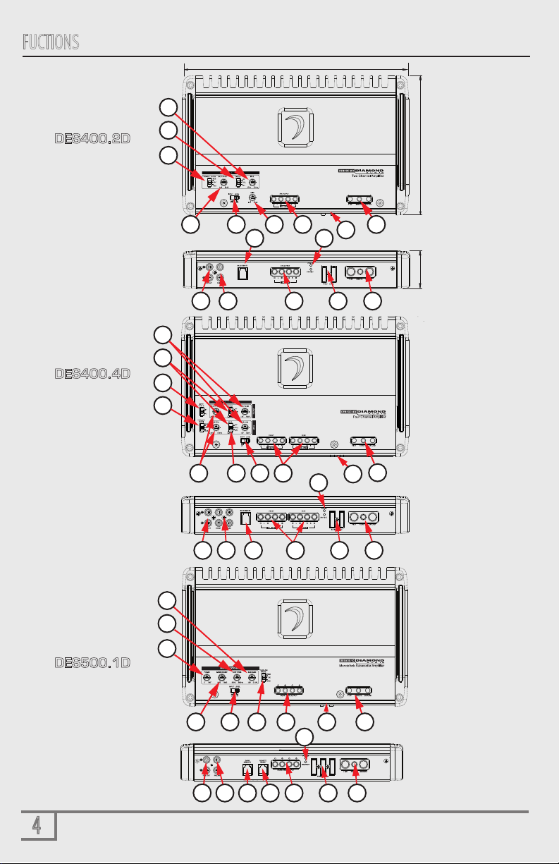
FUCTIONS
4
12
7.25”/184.2mm
11.81”/299.9mm
2.0”/50.8mm
4
8
6
7
12
9
7 15
3
6
6
2
4
10 14
11
7
2
16
10 14 17 15
9
12 13
15
1
14
4
8 5
16 15
14
10 9
16
5
15
14 16
1
16
1
5 2 14 15
SPECIAL NOTE:
ALL AMPLIFERS
ON THIS PAGE
ARE THE SAME
DIMENSIONS
DES400.2D
DES400.4D
DES500.1D
FUNCTIONS
5
STATUS - These lights indicate when the amplifier is powered up normally and when there is a protection fault. The Protect
LED is illuminated when there is a problem with your amplifier. Please contact your authorize DAT dealer or call DAT’s technical support.
1
GAIN - This control matches the preamp stage of the Diamond Audio amplifier to your source unit. This is NOT a volume control.
The range is between approx. 0.15mV to 12V. Use a speaker to RCA adapter (NOT an LOC!).
2
RCA INPUT (PRE INPUT) - The RCA jacks allow for a normal Left and Right channel signal input. Both HI (speaker level) or LO
(RCA’s). Simply connect to the source unit using RCA type audio cables (twisted pair is recommended), or use speaker to RCA adapters.
Make sure to keep them away from power wiring wherever possible to reduce risk of noise.
9
BASS BOOST - This control adds 0 to +12dB of Bass boost at 45Hz. Be cautious when adding boost to subwoofer systems as they
may not be able to handle the additional low frequency boost.
8
BASS REMOTE - All DES amplifers have this port for the remote level control (included). The control is intended to allow the
user to control the level of gain up to the maximum adjustment level set on the amplifier for the subwoofer output. The control does not
add additional boost, it only attenuates the setting that is fixed at the amplifier’s control panel.
12
POWER INPUT - These connections are for input power, chassis ground, and remote turn-on. Use a minimum of 8 gauge wiring for
power and ground connections. 4 Guage is recommended for the mono block. The terminals will handle up to 4 gauge wiring
with no problem whatsoever. Be sure any wiring that passes through metal has a grommet! DO NOT USE CCA power/ground wire!!
15
BASS REMOTE “Slave” - This OUTPUT allows you to control two (2) monoblock subwoofers amplifiers BASS BOOST - with
ONE (1)remote level contrrol!
13
11 PHASE- This control gives the installer a unique feature that allows the variable adjusment of phase 0-180 degrees to compensate for
subwoofer placement. Allowing the subwoofer to sound like it’s placed in the front of the vehicle instead of the trunk.
INPUT CONFIG - This switch parallels the input circuit if you are using a single stereo pair of outputs from your headunit
or from an auxiliary device (like a Smartphone, etc). The 5 channel model (DES1000.5D) is set up to accept 2/4/and 5 channels of input.
3
7FREQ - Use this adjustment to select the crossover point LPF/FLAT/ or HPF. Remember that you must select the crossover function
FIRST to get any adjustment. The range of adjustment is limited between 35-350Hz @12dB per octave .
6XOVER - This switch allows you to select the crossover function. HPF (High Pass Filter) LPF (Low Pass Filter) or FLAT(no filter),
HPF is for filtering out bass for midrange/mid bass drivers. LPF is for filtering out hIgh frequencies for subwoofers.
14 SPEAKER OUTPUT - Connect your speakers to these terminals. Stereo connections are connected as labeled. Bridged connections use
the LEFT + and RIGHT - as the two connections. The 2 and 4 channel amplifiers will perform into 4 and 2 Ohm stereo loads or 4 Ohm
bridged loads. DO NOT run 2 Ohm bridged loads on these amplifiers! The mono blocks will run 1 ohm mono.
4TURN-ON MODE - This switch allows you to configure the “Turn-On Mode” switch for desired turn-on trigger. There are 3 modes available:
REM, DC and VOX. 1 - (REM) is the standard 12V trigger wire, 2 - (DC) or DC offset, when connected high level in, will sense differences in
ground in your wiring through the speaker leads and turn on amplifier, 3 - VOX (signal sensing) which will sense any signal input into the
amplifier RCA input - turning on the amplifier.
RCA OUTPUT (PRE OUTPUT) - These RCA output jacks allow for Left and Right channel signal pass thru to a secondary amplifier.
This is available on the following DES amplifiers - DES400.2D/400.4D/1000.1D. It is NOT processed, and is full range/Unity Gain.
10
FUSES - Fuses are installed on ALL DES amplifers to protect ...the VEHICLE! They do NOT protect the amplifier. This is true of every amplifier
built today. IF you “blow” fuses, then check your electrical system. AGAIN - make sure you DO NOT use CCA wire power kits!!!
THIS VOIDS your warranty - NO EXCEPTION!
16
5INPUT LEVEL - This switch allow you to select HI or LO depending on the signal used. HI is used when you use speaker level
input. LO is when you use RCA input from an aftermarket headunit.
6
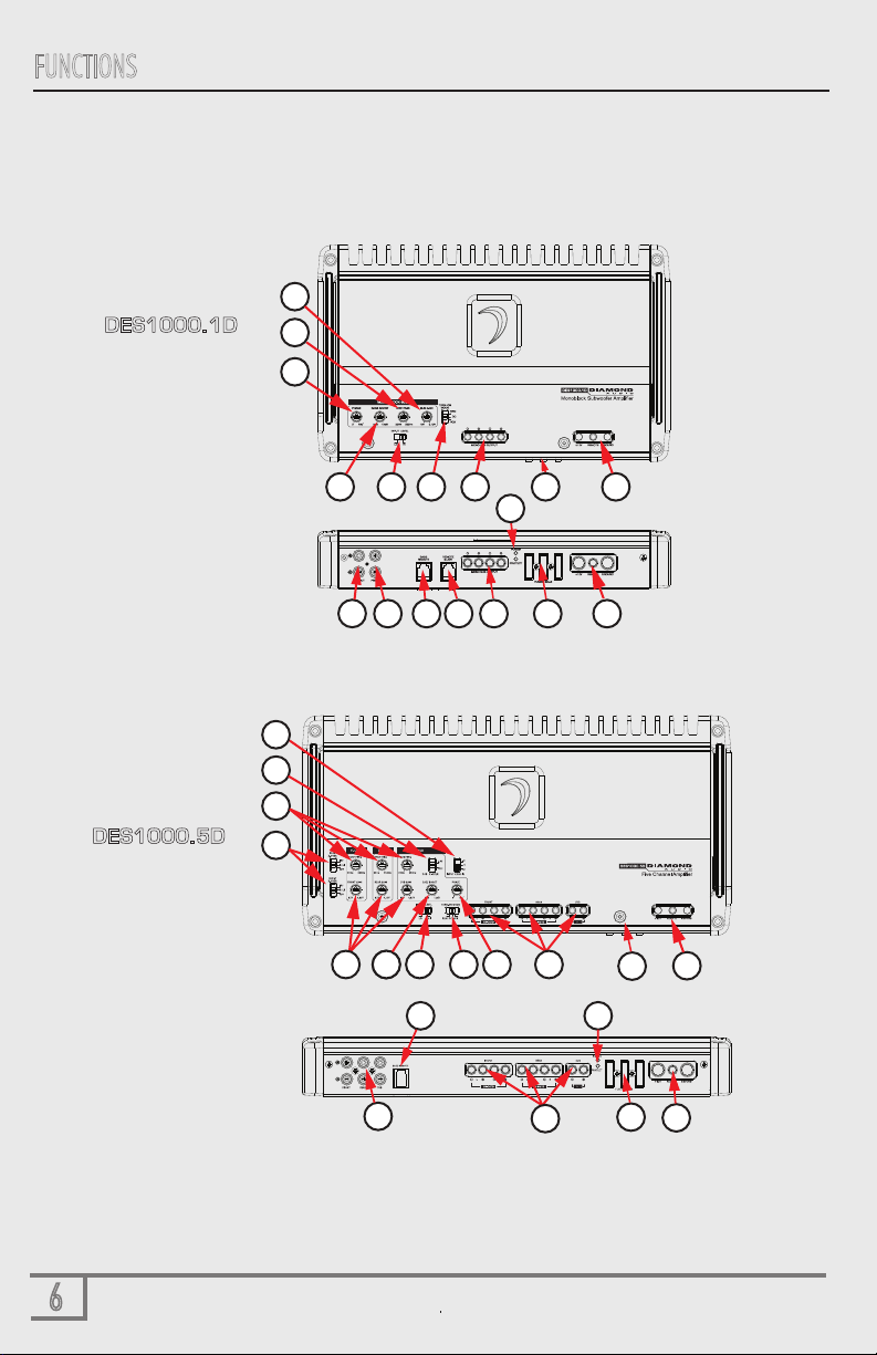
FUNCTIONS
8
11
15
10 14
7
2
16
915
1
12
11
6
15
7
3
16
13
12
16
14
1
5
16 15
9
6
58
4
514
24
14
DES1000.1D
DES1000.5D

FUNCTIONS
7
STATUS - These lights indicate when the amplifier is powered up normally and when there is a protection fault. The Protect
LED is illuminated when there is a problem with your amplifier. Please contact your authorize DAT dealer or call DAT’s technical support.
1
GAIN - This control matches the preamp stage of the Diamond Audio amplifier to your source unit. This is NOT a volume control.
The range is between approx. 0.15mV to 12V. Use a speaker to RCA adapter (NOT an LOC!).
2
RCA INPUT (PRE INPUT) - The RCA jacks allow for a normal Left and Right channel signal input. Both HI (speaker level) or LO
(RCA’s). Simply connect to the source unit using RCA type audio cables (twisted pair is recommended), or use speaker to RCA adapters.
Make sure to keep them away from power wiring wherever possible to reduce risk of noise.
9
BASS BOOST - This control adds 0 to +12dB of Bass boost at 45Hz. Be cautious when adding boost to subwoofer systems as they
may not be able to handle the additional low frequency boost.
8
BASS REMOTE - All DES amplifers have this port for the remote level control (included). The control is intended to allow the
user to control the level of gain up to the maximum adjustment level set on the amplifier for the subwoofer output. The control does not
add additional boost, it only attenuates the setting that is fixed at the amplifier’s control panel.
12
POWER INPUT - These connections are for input power, chassis ground, and remote turn-on. Use a minimum of 8 gauge wiring for
power and ground connections. 4 Guage is recommended for the mono block. The terminals will handle up to 4 gauge wiring
with no problem whatsoever. Be sure any wiring that passes through metal has a grommet! DO NOT USE CCA power/ground wire!!
15
BASS REMOTE “Slave” - This OUTPUT allows you to control two (2) monoblock subwoofers amplifiers BASS BOOST - with
ONE (1)remote level contrrol!
13
11 PHASE- This control gives the installer a unique feature that allows the variable adjusment of phase 0-180 degrees to compensate for
subwoofer placement. Allowing the subwoofer to sound like it’s placed in the front of the vehicle instead of the trunk.
INPUT CONFIG - This switch parallels the input circuit if you are using a single stereo pair of outputs from your headunit
or from an auxiliary device (like a Smartphone, etc). The 5 channel model (DES1000.5D) is set up to accept 2/4/and 5 channels of input.
3
7FREQ - Use this adjustment to select the crossover point LPF/FLAT/ or HPF. Remember that you must select the crossover function
FIRST to get any adjustment. The range of adjustment is limited between 35-350Hz @12dB per octave .
6XOVER - This switch allows you to select the crossover function. HPF (High Pass Filter) LPF (Low Pass Filter) or FLAT(no filter),
HPF is for filtering out bass for midrange/mid bass drivers. LPF is for filtering out hIgh frequencies for subwoofers.
14 SPEAKER OUTPUT - Connect your speakers to these terminals. Stereo connections are connected as labeled. Bridged connections use
the LEFT + and RIGHT - as the two connections. The 2 and 4 channel amplifiers will perform into 4 and 2 Ohm stereo loads or 4 Ohm
bridged loads. DO NOT run 2 Ohm bridged loads on these amplifiers! The mono blocks will run 1 ohm mono.
4TURN-ON MODE - This switch allows you to configure the “Turn-On Mode” switch for desired turn-on trigger. There are 3 modes available:
REM, DC and VOX. 1 - (REM) is the standard 12V trigger wire, 2 - (DC) or DC offset, when connected high level in, will sense differences in
ground in your wiring through the speaker leads and turn on amplifier, 3 - VOX (signal sensing) which will sense any signal input into the
amplifier RCA input - turning on the amplifier.
RCA OUTPUT (PRE OUTPUT) - These RCA output jacks allow for Left and Right channel signal pass thru to a secondary amplifier.
This is available on the following DES amplifiers - DES400.2D/400.4D/1000.1D. It is NOT processed, and is full range/Unity Gain.
10
FUSES - Fuses are installed on ALL DES amplifers to protect ...the VEHICLE! They do NOT protect the amplifier. This is true of every amplifier
built today. IF you “blow” fuses, then check your electrical system. AGAIN - make sure you DO NOT use CCA wire power kits!!!
THIS VOIDS your warranty - NO EXCEPTION!
16
5INPUT LEVEL - This switch allow you to select HI or LO depending on the signal used. HI is used when you use speaker level
input. LO is when you use RCA input from an aftermarket headunit.

8
8
SYSTEM SETUP
VEHICLE ELECTRICAL SYSTEM
Amplifiers (regardless of brand name) will put an increased load on the vehicle's battery and charging system. Diamond Audio
recommends checking your alternator and battery condition to ensure that the electrical system has enough capacity to handle
the increased load of your stereo system. Original equipment electrical systems which are in good condition should be able to
handle the extra load of any Diamond Audio amplifier without problems, although battery and alternator life can be reduced
depending on your individual listening habits. To maximize the performance of your amplifier, we suggest the use of a reserve
power "Stiffening" capacitor (1 Farad per 1000W).
WARNING:
Avoid running power wires near the low level input cables, antenna, power leads, sensitive equipment or harnesses. The power
wires carry substantial current and could radiate noise into the audio system through the audio cables.
1. Plan the wire routing as described in the "Importance of Pre-Planning" section. Keep RCA cables close together but isolated
from the amplifier's power cables and any high power vehicle accessories, especially electric motors. This is done to prevent
coupling the noise from radiated electrical fields into the audio signal. When feeding the wires through the firewall or any
metal barrier, protect them with plastic or rubber grommets to prevent short circuits. Leave the wires long at this point to
adjust for a precise fit at a later time.
2. Prepare the power wire for attachment to the amplifier
by stripping 5/8 inch (15.9mm) of insulation from the
end of the wire. Insert the bare wire into the B+
terminal and tighten the set screw to secure the cable
in place.
WARNING:
The B+ cable MUST be fused 18" or less from the
vehicle's positive battery post. Choose a location to
install a waterproof fuseholder under the hood and
ensure connections are water tight. If you do not use
the appropriate fuseholder, the connection will
eventually suffer corrosion from moisture and heat.
3. Trim the power cable within 18 inches (45.7mm)
of the positive battery post and splice in an in-line
fuse holder. DO NOT install the fuse at this time.
4. Strip 1/2 inch (12.7mm) from the battery end
of the power cable. Crimp and soldier a large ring
terminal to the cable. Connect the ring terminal to
the positive (+) battery post.
+
Front/Rear
Speaker setup
(2 W on front channels)

9
SYSTEM SETUP
5. Prepare the ground wire for attachment to the amplifier by stripping 5/8” of insulation from the end of the wire. Always
use a wire of the same gauge as the power connection, never smaller. Insert the bare wire into the GND terminal and
tighten the set screw to secure the cable in place. Prepare the chassis ground by scraping any paint from the metal surface
and thoroughly clean the area of all dirt and grease. Strip the other end of the wire, crimp and solder a ring connector.
Fasten the cable to the chassis using a non-anodized screw with a star washer and a nut.
WARNING: It is important to upgrade the ground
connection between the negative (-) battery post and the
vehicle body or chassis to achieve optimum electrical
performance.
6. Prepare the REM turn-on wire for attachment to the amplifier
by stripping 5/8 inch (15.9mm) of insulation from the end
of the wire. Insert the bare wire into the REM terminal and
tighten the set screw to secure the wire in place. Connect the
other end of the REM wire to a switched 12 volt positive
source. The switched voltage is usually taken from the
source unit’s remote amp turn on lead. If the source unit
does not have this output available, the recommended
solution is to wire to an accessory terminal in the car’s fuse
block using a relay to isolate the amplifer from the vehicles
accessory circuit. This however will turn the amplifier on and
off with the ignition key, regardless of whether the car stereo
is on or off.
7. Securely mount the amplifier to the vehicle or amp rack. Be careful not to mount the amplifier on cardboard or plastic
panels. Doing so may enable the screws to pull out from the panel due to road vibration or sudden vehicle stops.
8. Connect from source signal by connecting the RCA audio cables to the input jacks at the amplifier.
BATTERY FUSE RATINGS
9. Connect the vehicle speakers. Speakers impedance should never be less than 2 Ohms stereo, 4 Ohms bridged.
For most applications 18 gauge wire is adequate for the speaker leads. For leads in excess of ten feet, 16 gauge
wire is recommended. Strip the speaker wires 1/2” (12.7mm) and insert into the speaker terminal block then tighten
the set screw to secure into place. When wiring the speakers, pay careful attention to the polarity of the terminals on
the speakers and make certain they correspond to the polarity on the amplifier. DO NOT chassis ground any of the
speaker leads as unstable operation or damage to the amplifier and/or speaker may result.
400.2D = 50A
400.4D = 60A
500.1D = 90A
1000.1D = 60A
1000.5D = 90A
BY AMPLIFER MODEL
SPECIAL NOTE: DO NOT EXCEED THESE
FUSE RATINGS AND NEVER USE CCA WIRE!
RCA CONNECTION DIAGRAM

SYSTEM SETUP
10
Placing the XOVER switch in the FULL position sets the amplifier to Full Range. This
setting allows ALL frequencies to pass to the speakers. With placing the switch in the
HPF or LPF position activates the 12dB crossover, adjustable from 35Hz - 350Hz. The
500.1D/1000.1D mono is dedicated for Low Pass (LPF) only with an adjustable
frequency from 35Hz - 350Hz. The DES1000.5D (5 channel) amplifier offers full
range (FULL) high pass (HPF) or low pass (LPF) selector switch for channels 1-4.
Channel. Sub channel is LPF or OFF (for DSP processing)
Placing the switch in the HPF position sets the amplifier to the High Pass Filter mode,
enabling frequencies above the cutoff point to pass. Placing the switch in the LPF position sets the amplifier to the Low Pass
Filter mode, enabling frequencies below the cutoff point to pass. For system tuning begin with the frequency set at
approximately 80Hz and fine tune up or down based on music choice and input level.
To adjust the gain setting, turn the amplifier gains all the way down (counterclockwise). If using a remote level control (ALL
DES amplifiers), plug the level control into the amplifier and turn it to about "HALF-WAY" (approx. the 12 O'clock position)
this setups the bass boost so you can turn it UP...OR... turn it DOWN when playing different music styles. Next turn the source
unit volume up to almost full volume (usually about 2/3rds of the way up) or until the output starts to distort on an
oscilloscope. This will be NEARLY full volume on most source units, perhaps one or two "clicks" down from maximum volume.
Next, increase the amplifier gain setting until adequate volume is achieved, or until distortion is audible and then turn it down
a bit until the distortion is inaudible.
NOTE: Ideal signal to noise and dynamic range are achieved with the gain at minimum. Most users find adequate gain
and volume is achieved at less than halfway in the adjustment range. Avoid setting the amplifier gain very high as
noise and distortion will increase significantly. For a more in depth level setting (gain adjustment) procedure, visit the
Diamond Audio website.
The HPF or LPF crossover adjustment can now be fine tuned. If you are using the amplifier in a HPF configuration and would
like the system to be a little bit louder you can increase the HPF Filter frequency and reset the "Gain" of the amplifier. Raising
the HPF frequency up too high however will cause a loss of mid range and bass. If you are using the amplifier in a LPF
configuration and you hear voice or vocals coming from your subwoofer system you can turn the LPF frequency down (lower).
After setting the input gain adjustment and crossover, you may choose to add a small amount of “Bass Boost" in the low
frequency region. Remember that the Bass Boost feature will not fix a poorly designed subwoofer enclosure or subwoofers
that didn't sound good to begin with.
1. Make sure any bass EQ or low frequency equalization from the source unit is set to OFF or FLAT.
2. While playing the same musical selections used during the gain setting process, slowly increase the level of the Bass
Boost. You should be able to notice a change between 0 and +12dB. At the same time adjust frequency slowly from
35 -350Hz. If you do not notice much difference, then it will not serve any benefit to increase the boost further.
3. If the boost has audible benefits without adding appreciable distortion, find a level that suits your taste. Remember: it's
much easier to construct the right subwoofer enclosure for your listening preferences than relying on a bass boost control
to do the job!
350Hz35Hz

SYSTEM SETUP
11
Placing the XOVER switch in the FULL position sets the amplifier to Full Range. This
setting allows ALL frequencies to pass to the speakers. With placing the switch in the
HPF or LPF position activates the 12dB crossover, adjustable from 35Hz - 350Hz. The
500.1D/1000.1D mono is dedicated for Low Pass (LPF) only with an adjustable
frequency from 35Hz - 350Hz. The DES1000.5D (5 channel) amplifier offers full
range (FULL) high pass (HPF) or low pass (LPF) selector switch for channels 1-4.
Channel. Sub channel is LPF or OFF (for DSP processing)
Placing the switch in the HPF position sets the amplifier to the High Pass Filter mode,
enabling frequencies above the cutoff point to pass. Placing the switch in the LPF position sets the amplifier to the Low Pass
Filter mode, enabling frequencies below the cutoff point to pass. For system tuning begin with the frequency set at
approximately 80Hz and fine tune up or down based on music choice and input level.
To adjust the gain setting, turn the amplifier gains all the way down (counterclockwise). If using a remote level control (ALL
DES amplifiers), plug the level control into the amplifier and turn it to about "HALF-WAY" (approx. the 12 O'clock position)
this setups the bass boost so you can turn it UP...OR... turn it DOWN when playing different music styles. Next turn the source
unit volume up to almost full volume (usually about 2/3rds of the way up) or until the output starts to distort on an
oscilloscope. This will be NEARLY full volume on most source units, perhaps one or two "clicks" down from maximum volume.
Next, increase the amplifier gain setting until adequate volume is achieved, or until distortion is audible and then turn it down
a bit until the distortion is inaudible.
NOTE: Ideal signal to noise and dynamic range are achieved with the gain at minimum. Most users find adequate gain
and volume is achieved at less than halfway in the adjustment range. Avoid setting the amplifier gain very high as
noise and distortion will increase significantly. For a more in depth level setting (gain adjustment) procedure, visit the
Diamond Audio website.
The HPF or LPF crossover adjustment can now be fine tuned. If you are using the amplifier in a HPF configuration and would
like the system to be a little bit louder you can increase the HPF Filter frequency and reset the "Gain" of the amplifier. Raising
the HPF frequency up too high however will cause a loss of mid range and bass. If you are using the amplifier in a LPF
configuration and you hear voice or vocals coming from your subwoofer system you can turn the LPF frequency down (lower).
After setting the input gain adjustment and crossover, you may choose to add a small amount of “Bass Boost" in the low
frequency region. Remember that the Bass Boost feature will not fix a poorly designed subwoofer enclosure or subwoofers
that didn't sound good to begin with.
1. Make sure any bass EQ or low frequency equalization from the source unit is set to OFF or FLAT.
2. While playing the same musical selections used during the gain setting process, slowly increase the level of the Bass
Boost. You should be able to notice a change between 0 and +12dB. At the same time adjust frequency slowly from
35 -350Hz. If you do not notice much difference, then it will not serve any benefit to increase the boost further.
3. If the boost has audible benefits without adding appreciable distortion, find a level that suits your taste. Remember: it's
much easier to construct the right subwoofer enclosure for your listening preferences than relying on a bass boost control
to do the job!
4.TURN-ON MODE OPTIONS - Configure the “Turn-On Mode” switch for desired turn-on trigger. There are 3 modes available
on the DES series amplifier, REM, DC and VOX. 1 - (REM) is the standard 12V trigger wire, 2 - (DC) or DC offset, when
connected high level in, will sense differences in ground in your wiring through the speaker leads and turn on amplifier,
3 - VOX (signalsensing) will sense signal input into the amplifier RCA INPUT turning on the amplifier. DIAMOND AUDIO
Bluetooth Controller. The most preferred and reliable method is using the REM setting with a 12V trigger wire connected
to the vehicles ignition and will provide instant on and off for the amplifier. VOX and DC will provide turn on capabilities
for the amplifier when a 12V trigger wire is not available. These methods will have some delay in turning the amplifier
on and off.
5. REMOTE LEVEL/REMOTE LEVEL “SLAVE” – These RJ11 ports are specifically designed to be used with the DIAMOND
AUDIO BASS REMOTE controller. This will allow direct plug in control (level)of the subwoofer output. It is a proprietary
design and can ONLY be used with Diamond Audio amplifiers. This controller allows the user to adjust the subwoofer
level control totally seperate from the bass EQ that is in your car audio source unit. It is a GAIN control that specifically
controls the subwoofers level from 0 to +12dB more GAIN. Be careful as this will cause distortion at high levels as no
car audio amplifier has 12 dB of gain (this is equivalent to 20 times more power output DEMAND when the Remote
Bass knob is turned all the way up - clockwise) Assuming you have a 1,000 watt monoblock (like a DES1000.1D) you
would be asking the amplifer to produce 20,000 watts for a brief period of time. Also with our DES500.1D and
DES1000.1D there is an additional RJ11 Remote Bass Slave Port (See below). This makes using 2 DES monoblock
amplifiers subwoofer level adjustment simple using only ONE (1) Remote Bass Control. See below:
DES500.1D/DES1000.1D
”SLAVE”
PASS THRU from
“MASTER” AMP
DES500.1D/DES1000.1D
”MASTER”
Remote Bass
Control
To Sub
6 pin RJ11 cord
To Sub
“SWITCHED”
12 VOLTS “VOX” VOICE
ACTIVATED
(signal sensing)
DC “OFFSET”
INPUT from
HeadUnit (sub out)
Speaker level Input (Hi Level)
SYSTEM CONFIGURATIONS
12
This is for OEM radios with NO RCA outputs, only speaker outputs. For
each speaker or subwoofer that you plan to drive, with an amplifier
channel, strip back a small part of your vehicle's color-coded left and right
speaker wires then splice in the wires that lead to your amplifier.
(Solder or crimp, and secure the connection for optimum performance.)
NOTE: Amplifying front seat speakers will require you to run wiring thru a
door jamb or the floor carpeting to reach the speakers. Likewise, if your
amp is under a front seat, the front speakers are more accessible than the
rear ones. If your amp is in your trunk, it's a relatively short path to rear
deck speakers or a subwoofer.
HEAD UNIT
(perferredly with 5V output)
Front/Rear
Speaker setup
(4 /2 W on front channels)
ESC
VIEW
BAND
SOURCE
AUDIO
MUTE FUNC
TAG
Switched 12 V Out
from Headunit
5 Channel DES1000.5D
(front panel connection)
Sub Out
from Headunit
Rear Out
from Headunit
Front Out
from Headunit
Since the DES series amplifiers can take speaker level
in , here is the simpliest way to use it. Get an in-expensive
pair of RCA’s. Cut the cable about 18 inches back.
Strip the left and right wires to connect to
the OEM amplifier/Headunits speaker
outputs then plug directly into the DES
RCA input harness. Just switch how
Turn-On works (REM/DC/VOX)
SPEAKER LEVEL INPUT (OPTIONAL):
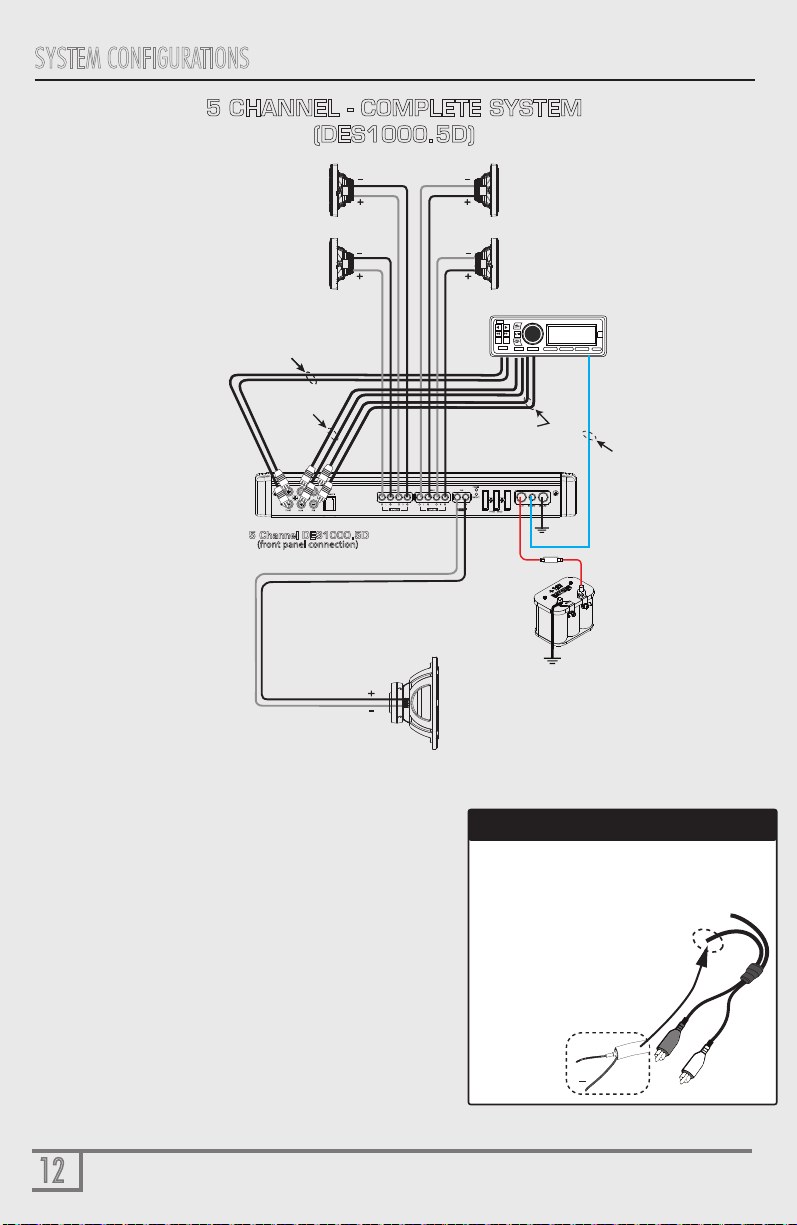
5 CHANNEL - COMPLETE SYSTEM
(DES1000.5D)
+
Once stripped as
(shown to the right)
solder the speaker
leads from your OEM
headunit
Subwoofer (4Wload)

13
SYSTEM CONFIGURATIONS
13
SYSTEM CONFIGURATIONS
HEAD UNIT
(perferredly with 5V output)
Front/Rear
Speaker setup
(2 W on front channels)
ESC
VIEW
BAND
SOURCE
AUDIO
MUTE FUNC
TAG
Subwoofer (4Wload)
Rear Channels Bridged Mono
to 4 ohm woofer
Switched 12 V Out
from Headunit
4 CHANNEL - DES400.4D
3 CHANNEL MODE
4 Channel DES400.4D
(front panel connection)
Front Out
from Headunit
Rear Out
from Headunit
SYSTEM CONFIGURATIONS
14
Front/Rear
Speaker setup
(4/2 Won ALL channels)
HEAD UNIT
(perferredly with 5V output)
Switched 12 V Out
from Headunit
FRONT Out
from Headunit
ESC
VIEW
BAND
SOURCE
AUDIO
MUTE FUNC
TAG
Remote Bass
Control
5 CHANNEL -COMPLETE SYSTEM
(DES400.4D/DES1000.1D)
4 Channel DES400.4D
(front panel connection)
1 Channel DES500.1D
(front panel connection)
PASS THRU from AMP
REAR Out
from Headunit
Subwoofer (2 OR 1Wload)

SYSTEM CONFIGURATIONS
15
DES400.2D
STEREO ( 1 AMP/4 SPEAKERS - 2 0HM LOAD)
HEAD UNIT
(perferredly with 5V output)
Total Speaker Impedance (MIN 2Ω)
Front Speakers(4/2Ω)
Rear Speakers(4Ω)
2 Channel DES400.2D
(front panel connection)
ESC
VIEW
BAND
SOURCE
AUDIO
MUTE FUNC
TAG
PASS THRU from AMP
to SUB AMPLIFIER
SYSTEM CONFIGURATIONS
16
1 Channel DES1000.1D
(front panel connection)
1 Channel DES1000.1D
(front panel connection)
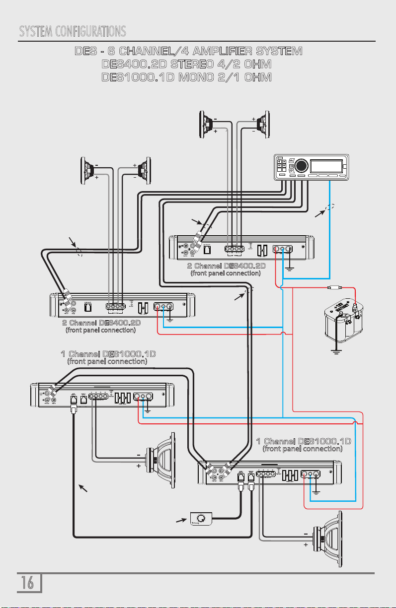
DES - 6 CHANNEL/4 AMPLIFIER SYSTEM
DES400.2D STEREO 4/2 OHM
DES1000.1D MONO 2/1 OHM
SUB Out
from Headunit
Remote Bass
“SLAVE” Connection
FRONT
Speaker setup
(4/2 ohms on ALL channels)
Switched 12 V Out
from Headunit
Remote Bass
Control
REAR
Speaker setup
(4/2 ohms on ALL channels)
HEAD UNIT
(perferredly with 5V output)
ESC
VIEW
BAND
SOURCE
AUDIO
MUTE FUNC
TAG
2 Channel DES400.2D
(front panel connection)
2 Channel DES400.2D
(front panel connection)
REAR Out
from Headunit
FRONT Out
from Headunit
Subwoofer (2 OR 1Wload)
Subwoofer
(2 OR 1Wload)

17
SPECIFICATIONS
DES400.2D DES400.4D DES1000.5D
Power Rating
Power Supply Full PWM Full PWM Full PWM
Power Supply Threshold 10.0VDC -
17.0VDC 10.0VDC -
17.0VDC 10.0VDC -
17.0VDC
Distortion
THD (1KHz @4Ω) 0.05% 0.07% 0.03%
S/N Ratio (A weighted @1W) -77.2dBA --77.4dBA --76.7dBA
S/N Ratio (A weighted @ FP) -98.9dBA -97.4dBA -96.7dBA
Input Sensitivity
Low Input Level 0.2mV - 12.0V 0.2mV - 10.0V 0.2mV - 10.0V
High Input Level
Input Impedance
Low Input Level
High Input Level
22 KΩ 22 KΩ 22 KΩ
Crossover (-12dB/Oct)
Variable High-Pass 35Hz - 350Hz 35Hz - 350Hz
35Hz - 350Hz
Variable Low-Pass
Variable Sub-Sonic
Fuse Ratings
35Hz - 350Hz
N/A
35Hz - 350Hz
N/A
35Hz - 350Hz
Power Supply
Output Stage
Output Impedance 0.047Ω 0.047Ω 0.051 Ω
Damping Factor (50Hz @ 4Ω) >250 >250 >70
Idle Current (0.7A) (0.7A) (0.7A)
ATC 2 X 30A
Dimensions
Lenght x Width x Height (inches)
Lenght x Width x Height (mm)
Bandwidth (-3dB) 10Hz-35KHz 10Hz-35KHz 10Hz-350Hz
Topology Full-Range Class D
Type
N/A
Full-Range Class D Full-Range Class D
RMS Power (2 Ω)
RMS Power (4 Ω)
Bridged (mono 1 Ω)
Bridged (mono 2 Ω)
Bridged (mono 4 Ω)
250 W X 2
200 W X 2
N/A
N/A
500 W X 2(4 Ω ONLY)
170 W X 4
140 W X 4
N/A
N/A
400 W X 2(4 Ω ONLY)
MODEL:
11.81 x 7.25 x 2.0
299.9 x 184.2 x 50.8
YES - UP to 25 W RMS YES - UP to 25 W RMS YES - UP to 25 W RMS
2 X 25A 3 X 40A
11.81 x 7.25 x 2.0
299.9 x 184.2 x 50.8
11.81 x 7.25 x 2.0
299.9 x 184.2 x 50.8
150 W X 4 /250 X 1
90 W X 4 /150 X 2
N/A
300 W X 2/500 W X 1(Ch 5/6 bridged)
N/A

18
SPECIFICATIONS
RMS Power (1Ω) 500 W X 1 RMS 1000 W X 1 RMS
RMS Power (2 Ω)
500 W X 1 RMS
400 W X 1 RMS
1000 W X 1 RMS
800 W X 1 RMS
RMS Power (4 Ω)
Power Rating
3 X 40A
3 X 40A
11.81 x 7.25 x 2.0
299.9 x 184.2 x 50.8
11.81 x 7.25 x 2.0
299.9 x 184.2 x 50.8
11.81 x 7.25 x 2.0
299.9 x 184.2 x 50.8
DES500.1D DES1000.1D
Power Supply Full PWM Full PWM
Power Supply Threshold 10.0VDC -
17.0VDC 10.0VDC -
17.0VDC
Distortion
THD (1KHz @4Ω) 0.05% 0.07%
S/N Ratio (A weighted @1W) -77.2dBA --77.4dBA
S/N Ratio (A weighted @ FP) -98.9dBA -97.4dBA
Input Sensitivity
Low Input Level 0.2mV - 10.0V 0.2mV - 10.0V
High Input Level YES - UP to 25 W RMS YES - UP to 25 W RMS
Input Impedance
Low Input Level 22 KΩ 22 KΩ
Crossover (-12dB/Oct)
Variable High-Pass N/A N/A
Variable Low-Pass
Variable Sub-Sonic
Fuse Ratings
35Hz - 350Hz 35Hz - 350Hz
Power Supply
Output Stage
Output Impedance 0.047Ω 0.047Ω
Damping Factor (50Hz @ 4Ω) >250 >250
Idle Current (0.7A) (0.7A)
ATC
Dimensions
Lenght x Width x Height (inches)
Lenght x Width x Height (mm)
Bandwidth (-3dB) 10Hz-350Hz 10Hz-350Hz
Topology MonoBlock Class D
Type
MonoBlock Class D
MODEL:
High Input Level 22 KΩ 22 KΩ
N/A N/A

19
WARRANTY
THIS WARRANTY IS NOT TRANSFERABLE AND APPLIES ONLY TO THE ORIGINAL PURCHASER OF THIS PRODUCT
IN ITS ORIGINAL INSTALLATION. Original purchaser must reside in the United States and be able to provide proof of
purchase and installation with the sales receipt and completion of online registration from the authorized DAT retailer that
sold and installed the product.
Should a manufacturing defect occur during above said warranty period, DAT will replace or repair the defective product
with a product of the same or equivalent value and performance, at DAT’s discretion.
Damage or failure caused by any of the following is not covered under this warranty policy: negligence, improper use,
abuse, product modification, unauthorized repair attempts, accident, acts of God, misrepresentations by DAT retailers, and
improper/inadequate packaging during return shipping.
Warranty is void if serial numbers have been removed, altered or defaced.
HOW TO OBTAINWARRANTY SERVICE
In the event a DAT product should require service, you should visit the authorized DAT retailer you purchased the product
from and they can expedite your claim. All claims must fall into the guidelines listed above and be accompanied by a copy of
the original sales and installation receipt from that authorized DAT retailer.
Product returned for warranty service must be freight-prepaid, properly packaged and clearly marked with the Return
Authorization (RA) number issued by DAT. Any product returned to DAT that is improperly packaged, does not have a
RA number clearly marked on the package, or never received a RA number, may be refused upon delivery. DAT does not
assume responsibility for lost or misdirected product.
Repair or replacement under this warranty is the exclusive remedy of the consumer. DAT shall not be liable for any
incidental or consequential damages for breach of any expressed or implied warranty on this product. Some states do not
allow the exclusion or limitation of incidental or consequential damages, or allow limitations on how long an implied warranty
lasts, so the above limitations or exclusions may not apply to you. This warranty gives you specific legal rights and you may
also have other rights that may vary from state to state.
Customers outside the United States should contact their local sales office to obtain information on pricing, exchange unit
availability, instructions, service and warranty/non-warranty replacement or repair.
Diamond Audio Technologies
1225 E.7th ST
LOS ANGELES,CA 90021
Tel: 213-261-4161
Fax: 213-947-4767
Web: diamondaudio.com
Service/Tech Support:
213-261-4161
Tech Support Email
Diamond Audio Technologies (DAT), a division of CV & DA Holdings Incorporated, warrants this product to be free from
defects in material and workmanship for a period of one (1) year from the original date of purchase, provided it was
purchased from an authorized DAT retailer within the United States. Product warranty period starts at the date of
purchase or one year past the manufacture date whichever is first. However, upon purchase and completion of the
on-line registration and installation by an authorized DAT dealer, warranty period will be extended to two (2) years.
This warranty extension offer will only be recognized upon completion of the on-line registration of your product within
thirty (30) days of the date of purchase.

Product specifications are subject to change without notice
Other manuals for DES Series
2
This manual suits for next models
5
Table of contents
Other Diamond Audio Amplifier manuals


Popular Amplifier manuals by other brands


C.E.C.
C.E.C. TUBE53 owner's manual

Alesis
Alesis TransActive Drummer quick start guide

Harman
Harman CROWN CDi Series System Technology Bulletin

Cary Audio Design
Cary Audio Design SLA-70B Signature operating manual
18-DI03-4S-4T1R Safety manual")
turck
turck IM(X)18-DI03-4S-4T1R Safety manual

Harman Kardon
Harman Kardon HK870 Technical manual