DIAMOND GEAR WG Series Instruction manual

www.australianpipelinevalve.com.au
INSTALLATION, OPERATION & MAINTENANCE MANUAL
WORM GEARBOX
QUARTER TURN
SERIES WG

View our catalogues at www.australianpipelinevalve.com.au
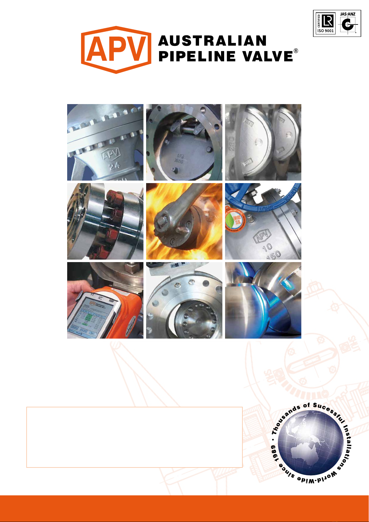
AUSTRALIAN PIPELINE VALVE BRAND RANGE -CATALOGUES
APV FAMILY OF BRANDS RANGE - CATALOGUES
COMPLETE
PRODUCT LINE
“Australian Pipeline Valve
produces isolation,
control and flow reversal
protection products for
severe and critical service
media in utility, steam,
pipelines, oil & gas
and process industries.
APV valves and pipeline
products form the most
competitive portfolio
in the market.”
Oilfield Products
Valves & Wellheads
Gate, Globe & Check
Valves - Forged Steel
Plug Valves Lubricated,
Sleeved & Lined
Gate, Globe & Check
Valves - Cast Steel
Diamond Gear
Gearboxes
Flowturn Gate, Globe
& Check Valves
Flowturn
Instrument Valves
Flowturn Ball Valves
Multiway & Deadman
Flowturn Strainers
& Sight Glasses
Supercheck
Wafer Check Valves
Superseal
Butterfly Valves
Steamco
Steam Valves
Superseal
Industrial Ball Valves
TwinLok Tube Fittings Uniflo Check ValvesTorqturn Actuators
Ball Valves Floating
& Trunnion Mounted
Ball Valves
Floating Small Bore
Ball Valves
Special Service
Product Brochure
Contact us for your local stockist/distributor

Introduction 2
Safety Information 3-4
1.0 Description 4
2.0 Storage 5
3.0 Operation 5
4.0 Installation 5-6
4.1 Setting adjustment screws 6
5.0 Troubleshooting 6
6.0 Maintenance 7
Appendix 1 - Typical design 8
Appendix 2 - Bill of materials 9-10
QUARTER TURN WORM GEARBOX - SERIES WG
INDEX
Australian Pipeline Valve - Installation, Operation and Maintenance Manual 1
© Copyright Australian Pipeline Valve 1990 - 2013 Edition
Catalogues, photos, brochures and technical publications are the exclusive property of Australian Pipeline Valve.
Any unauthorised reproduction in total or in part, shall result in prosecution. Products and data sheets in this publication are subject
to change at anytime without notice. Australian Pipeline Valve reserves the right to carry out amendments to products and materials.

QUARTER TURN WORM GEARBOX - SERIES WG
Australian Pipeline Valve - Installation, Operation and Maintenance Manual2
INTRODUCTION
The majority of this information is common knowledge to experienced valve and gearbox users. When
properly installed in applications for which they were designed, Australian Pipeline Valve (APV) - Diamond
Gear gearboxes will give long reliable service. This instruction is only a guide for installation and
operation on standard service and covers general maintenance and minor repairs. A professional APV
approved engineering facility should be utilised for reconditioning or major repairs.
RESPONSIBILITY FOR VALVE/GEARBOX APPLICATION
The User is responsible for ordering the correct gearboxes. The user is responsible for ensuring APV -
Diamond Gear gearboxes are selected and installed in conformance with the torque service and design
temperature requirements. Prior to installation, the gearbox drawing and nameplates should be checked
for proper identification to ensure the gearbox is of the proper type, material and is of a suitable size and
temperature rating to satisfy the requirements of the service application.
RECEIVING INSPECTION AND HANDLING
Gearboxes should be inspected upon receipt to ensure:
- Conformance with all purchase order requirements.
- Correct type, model, size, body and trim materials.
- Any damage caused during shipping and handling to end connections, hand wheel or stem.
Note
We do recommend however that this entire document be read prior to proceeding
with any installation or repair. Australian Pipeline Valve and it’s parent company
take no responsibility for damage or injury to people, property or equipment. It is
the sole responsibility of the user to ensure only specially trained valve repair
experts perform repairs under the supervision of a qualified supervisor.
Do not use gearboxes in applications where the temperature is higher than the
allowable working values. Gearboxes should not be used in environments if not
compatible with the gearbox materials of construction, as this will cause chemical
attacks, leakage, valve failure.
The User is advised that specifying an incorrect gearbox for the application may
result in injuries or property damage. Selecting the correct gearbox type, material
and mounting, in conformance with the required performance requirements is
important for proper application and is the sole responsibility of the user.
Australian Pipeline Valve - Installation, Operation and Maintenance Manual 3
QUARTER TURN WORM GEARBOX - SERIES WG
SAFETY INFORMATION
The following general safety information should be taken in account in addition to the specific warnings
and cautions specified in this manual. They are recommended precautions that must be understood and
applied during operation and maintenance of the equipment covered in this I.O.M.
This manual provides instructions for storing, general servicing, installation and removal of gearboxes.
APV and it’s resellers refuse any liability for damage to people, property or plant as well as loss of
production and loss of income under any circumstances but especially if caused by: Incorrect installation
or utilisation of the gearbox or if the gearbox installed is not fit for intended purpose. It is the sole
responsibility of the user to ensure the gearbox type and materials are correctly specified.
DURING OPERATION TAKE INTO ACCOUNT THE FOLLOWING WARNINGS:
a- The gearboxes internal parts shall be handled with care avoiding scratches or surface damage.
b- All tools and equipment for handling the internal parts shall be soft coated.
c- Gearboxes can be fitted with seals in Buna, Viton, etc., hence high temperatures will damage sealing
components.
For all operations make reference to position number on part list of the applicable drawing listed.
• Gearbox surface temperature may be dangerously too hot or too cold for skin
contact.
• Ensure adequate ventilation is available for service.
Personal injury may result from sudden release of any process pressure. APV
recommends the use of protective clothing, gloves and eye wear when performing
any installation or maintenance.
Isolate the valve from the system and relieve pressure prior to performing
maintenance.
Disconnect any operating line providing air pressure, control signals or electrical
power to actuators.
If a gasket seal is disturbed while removing or adjusting gasketed parts, APV
recommends installing a new gasket while reassembling. A proper seal is required
to ensure optimum operation.

Australian Pipeline Valve - Installation, Operation and Maintenance Manual4
QUARTER TURN WORM GEARBOX - SERIES WG
1.0 DESCRIPTION
The Diamond Gear WG series worm gear operators offer simple and reliable manual positioning of valves,
dampers and other quarter turn devices. All Diamond Gear WG units combine rugged construction, light
weight and modular design to provide the most efficient and cost effective solution for actuation of
process valves such as butterfly, ball and plug valves. WG series have an optional locking device.
Gearboxes should be sized with at least a 40% safety factor or even more if high or low temperature or
dirty service or infrequent use. Valves should be regularly opened to avoid sticking. Most valves will
increase in torque over time as debris, corrosion, increased pressure, erosion, infrequent use, sticking of
seats, etc., all effect torque. Bear in mind, some valves like plug valves need regular lubrication. Also the
theorectical torque of a valve can be dramatically different to the actual torque.
Potential HIGH PRESSURE vessel - be aware of high-pressure hazards associated with
the attached valve or other actuated device when installing or performing
maintenance on the operator. Do not remove the operator bolts from the valve or
actuated device unless the valve or device stem is secured or there is no pressure in
the line.
For maintenance and/or disassembly of the operator when installed on the valve,
ensure that the operator is not under thrust or torque load. If the valve must be left
in service, the valve stem must be locked in such a way as to prevent any movement
of the valve stem.
Do not manually operate the operator with devices other than the installed hand-
wheel. Using force beyond the ratings of the operator and/or using additive force
devices such as cheater bars, wheel wrenches, pipe wrenches, or other devices on
the operator handwheel may cause serious personal injury and/or damage to the
operator and valve.
Do not exceed any design limitations or make modifications to this equipment
without first consulting us.
Use of the product must be suspended any time it fails to operate properly.
Standard gearboxes are not suitable for motor actuation. A special heavy duty
version can be specified for this purpose.
Do not use replacement parts that are not genuine Diamond Gear parts, as serious
personal injury and/or damage to the operator and valve may result.

Australian Pipeline Valve - Installation, Operation and Maintenance Manual 5
QUARTER TURN WORM GEARBOX - SERIES WG
2.0 STORAGE
WG Gear Operators don’t have a shelf life however, store in a clean, dry area protecting the input and
output bores from corrosion and damage by sealing each unit in a plastic bag.
Store on wooden skids to protect the machined mounting flange. If the operators must be stored outside,
they must be covered in polyethylene with silica gel crystals to absorb moisture. Input shafts should be
rotated every three months to mix lubricant.
3.0 OPERATION
Operation of the hand wheel will actuate the process valve.
A limit Stop arrangement allows adjustment of the stroke by ±5° from either open or closed range. This
can be achieved by adjusting the two stroke limiting screws to the extent desired. For normal operation
of the valve, ensure the screws to be set in the extreme out position.
An open/close visual indicator on top of the gearboxes indicates degree open/closed. ‘Open’ and shut
indicators are marked, ensure they are correctly synchronised.
4.0 INSTALLATION
WG gearboxes can be direct mounted or fitted with a bracket and adaptor. Ensure adaptors are
manufactured from high strength steel such as 17-4PH, S31803, CR13, 410, 4140, XM-19, etc. Also ensure
only high tensile bolts are used to secure the gearbox and bracket. Gearboxes can be supplied with a pre
bored stem and keyway or with a small starter hole allowing client to machine. Do not machine a larger
shaft hole and keyway than the maximum shown in the WG brochure and drawing. After ensuring
mounting patterns are drilled and tapped correctly, install as follows: -
1. Ensure the valve and gear are in the same synchronised position (open or closed). Remove the gear
indicator to ensure the input bore and shaft lines up with the valve stem.
Note: Due to the different stop settings of each valve, the gearbox indicator may not be exactly
synchronised with the position of the valve. Accurate settings should be determined by the actual position
of the valves, plug, disc or ball.
2. Lower gear box over the valve stem onto the valve mounting pad, ensuring the mounting holes on the
bottom of the gear box align with the valve mounting pad or bracket.
3. Bolt the operator onto the bracket or valve then reinstall gear indicator ensuring the indicator is
correctly synchronised with the valve position.

Australian Pipeline Valve - Installation, Operation and Maintenance Manual
6
QUARTER TURN WORM GEARBOX - SERIES WG
4.1 SETTING ADJUSTMENT SCREWS
1. Move the valve to the fully closed position. Set the adjustment bolt clockwise until it makes contact
with the segment in the gear then lock the adjustment screw in place with the lock nut.
2. Move the valve to the fully open position.
Note: If the valve is installed in the line and you cannot see if the valve is full open, count the number of
turns of the handwheel required to reach 90 degrees. For example, if the gear box is a 100:1 ratio, rotate
the handwheel 25 times to reach 90 degrees. This can still be inaccurate and it is recommended to remove
the valve from the line and properly calibrate the operator at the next opportunity.
3. Set the other adjustment screw clockwise until it makes contact with the segment inside the gear. Lock
the adjustment screw with the lock.
5.0 TROUBLESHOOTING
Note
Do not use oversize handwheels or leverage/cheater bars. This can result in damage
to the gear box.
SL NO.FAULT PROBABLE CAUSE REMEDIAL ACTION
1. Valve not opening/
closing even when
handwheel is rotated
Worm to shaft mechanism broken
due to over loading.
Handwheel to shaft connection
failed, key sheared/ missing.
Open gear box and replace
damaged parts.
Check handwheel to shaft joint
and replace parts if broken.
2. Full open/ closing of
valve not achieved/
obtained
Improper adjustment of limit stop
screw on WG.
Fixing bolts between valve and
WG loose. Play between the joint.
Excessive play in adaptor linkage/
keyway.
Re-adjust limit stop screws and
lock in position.
Check mounting bewteen valve
and WG. Tighten nuts after
aliging in correct position.
Check linkage between valve
and shaft and gear box.
Replace key, if required.
3. Valve opening/ closing
found to be more than
90º, Over closing/
over opening
Improper adjustment of limit stop
screws.
Loosen locknuts. Adjust stopper
screws to the desired opening/
closing and tighten locknuts.
4. Excessive force
required for
handwheel rotation
Excessive valve torque. WG not
selected properly.
Check valve torque and replace
with higher size WG, if required.

Australian Pipeline Valve - Installation, Operation and Maintenance Manual 7
QUARTER TURN WORM GEARBOX - SERIES WG
6.0 MAINTENANCE
Gearboxes are factory pre greased for life depending on the environment and service, for water resistant
service. Inspect the internal gears and bearings annually and re-lubricate where required. Obviously for
special, critical or frequent service applications, inspect the internals more regularly. To inspect the
internals, remove cover bolts and indicator plate, O-rings and cover gasket. To inspect bearings, remove
screws from end caps. Always replace O-rings and gaskets before re-assembly.
Should extra lubricant be required, use suitable multipurpose grease containing ‘EP’ additive that is non
separating and contains no additive that will damage Viton or Buna O-rings.
Complete overhaul or extra ordinary repairs should be sent back to APV. However, it is usually cheaper to
replace the unit with a brand new operator. Refer to diagram 1 for typical bill of material explosion. Only
a gear box expert should attempt complete disassembly and repair.
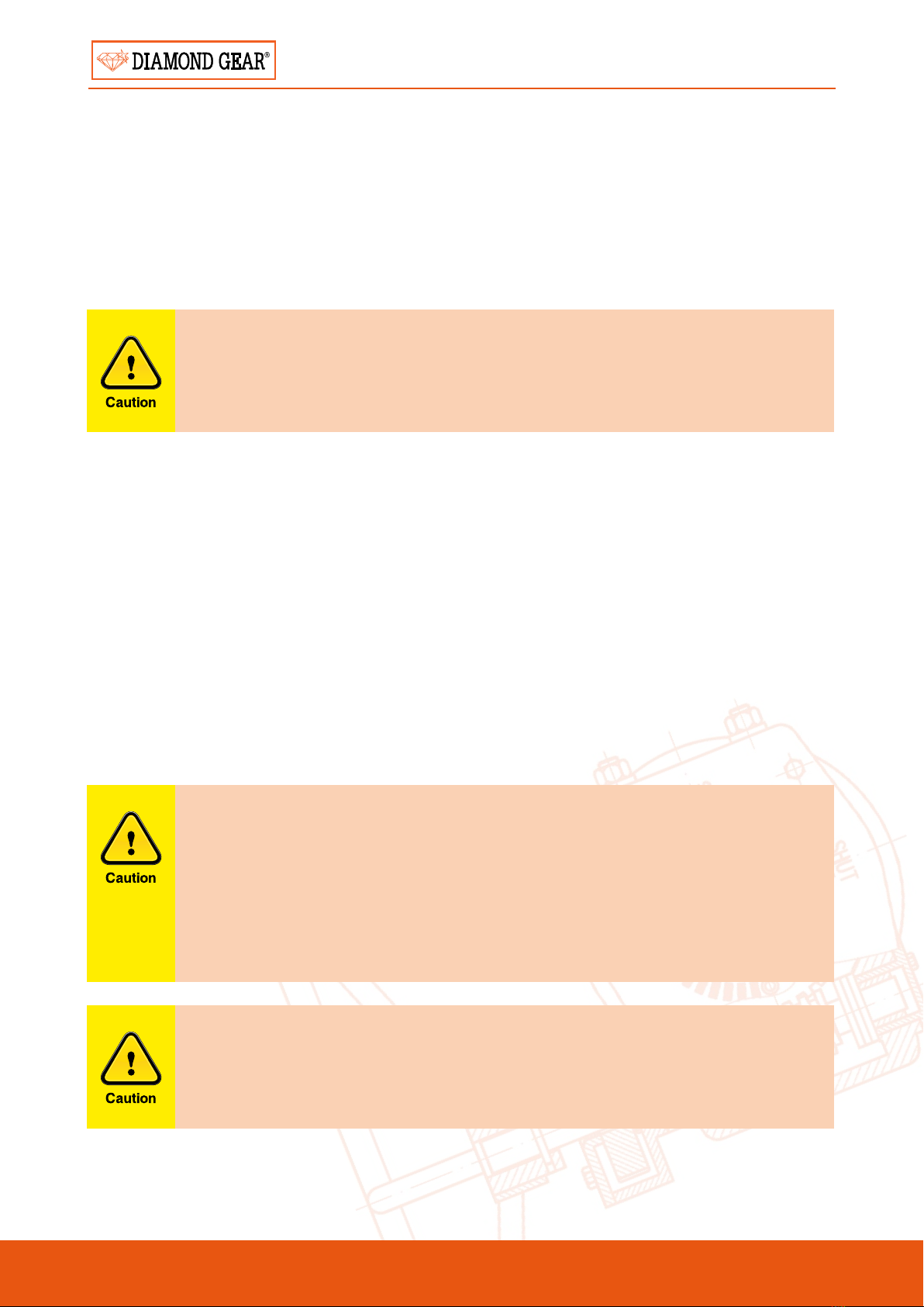
EXPLOSION DIAGRAM 1
Typical indicative explosion only refer to as-bult drawing, parts vary according to size/model.
Smaller size units do not have side cap ange.
Australian Pipeline Valve - Installation, Operation and Maintenance Manual8
QUARTER TURN WORM GEARBOX - SERIES WG
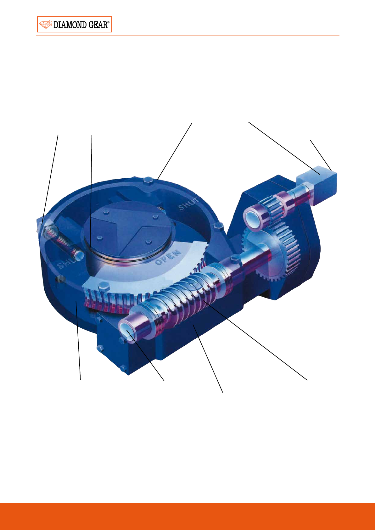
APPENDIX 1
DIAGRAM 2
* Optional heavy duty spur gear design required for motor operation.
Custom gear
mounting pattern,
boring and keyway
patterns.
Worm gear dual
position mounting
capability for easy
reversal of rotation
direction.
Comprehensive
product line for
torque capability.
Industry
inter-changeable
pre-drilled
mounting pattern
per MSS SP 101.
Machine generated
self-lock gearing
assures minimum
backlash and
smooth operation.
Optional square
operating nut allows
for removal of
handwheel and
operation by a
reach rod.
*Easily converted
for motorized
applications.
High strength
cast iron
enclosure.
O-ring sealed and
permanently
lubricated.
External
mechanical
stops
allow +/-50
travel.
Fully
weather
resistant
for outdoor
service.
Australian Pipeline Valve - Installation, Operation and Maintenance Manual 9
QUARTER TURN WORM GEARBOX - SERIES WG
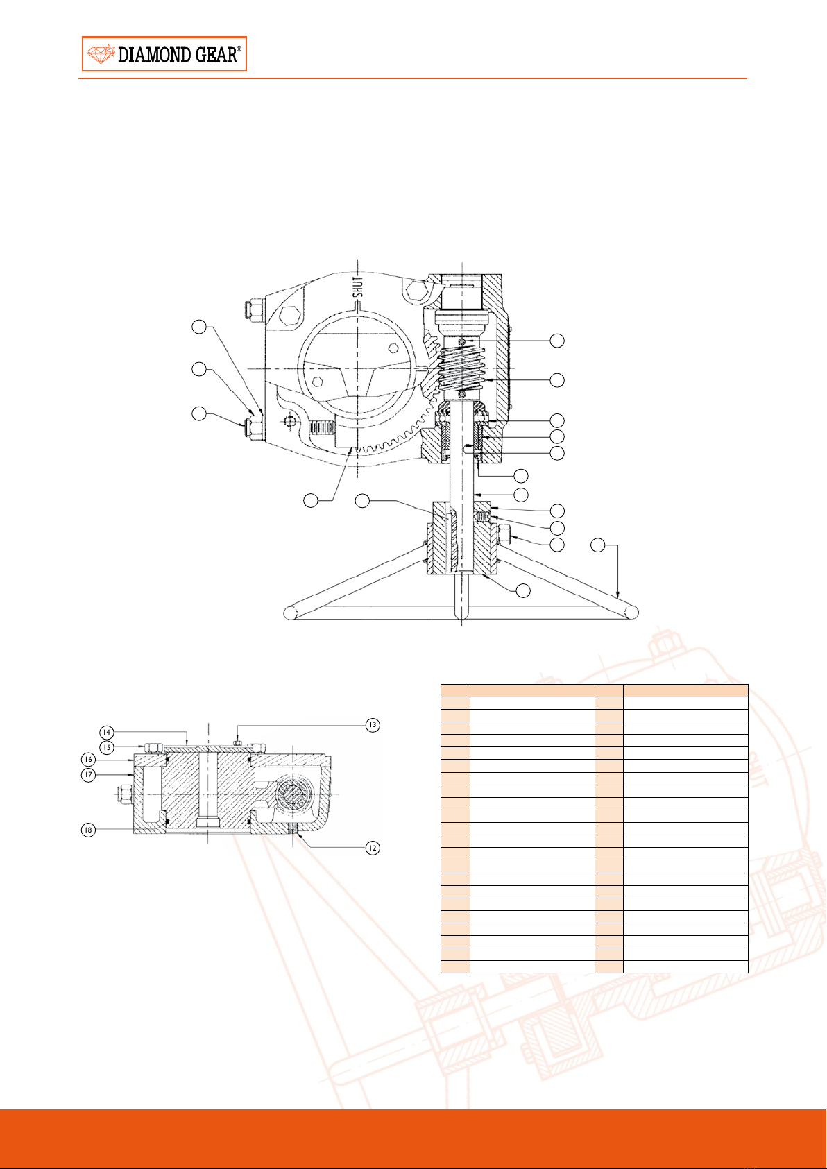
APPENDIX 2
WG008W ~ WG208W
DIAGRAM 3
Indicative drawing only. Refer to as-built drawing.
19 20
21
1
2
3
4
5
6
7
8
9
10
11
24
23
22
BILL OF MATERIALS
NO PART NAME QTY MATERIAL
1HANDWHEEL 1CARBON STEEL
2SET SCREW 1CARBON STEEL
3STEM KEY 1CARBON STEEL
4INPUT SHAFT 1AISI 1045
5OIL SEAL 1RUBBER
6BEARING 2Cu-BASE ALLOY
7OIL BEARING 2Cu-BASE ALLOY
8THRUST BEARING 2COMMERCIAL
10 WORM 1AISI 1045
12 PIN2CARBON STEEL
15 PLUG 2CARBON STEEL
16 BOLT 2CARBON STEEL
17 INDICATOR PLATE1CAST IRON
18 BOLT 4CARBON STEEL
19 COVER 1CAST IRON
20 HOUSING 1CAST IRON
21 O-RING 2RUBBER
23 WORM GEAR 1DUCTILE IRON
24 2” SQ. OPERATING NUT 1CARBON STEEL
25 STOP SCREW 2CARBON STEEL
26 HEX NUT 2CARBON STEEL
27 LOCKWASHER 2CARBON STEEL
14
15
16
17
18
13
12
Australian Pipeline Valve - Installation, Operation and Maintenance Manual10
QUARTER TURN WORM GEARBOX - SERIES WG
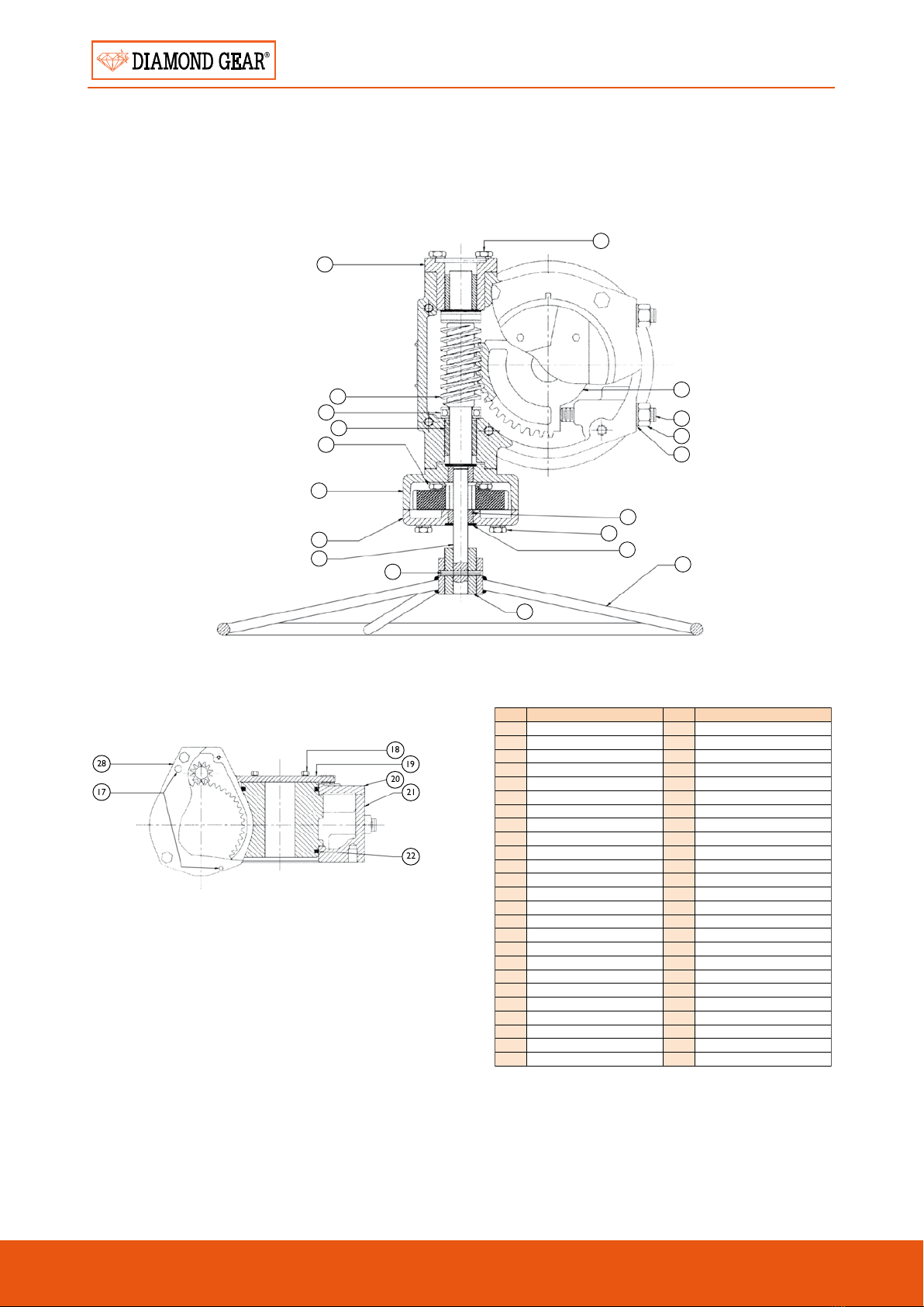
WG308W ~ WG508W
DIAGRAM 4
Indicative drawing only. Refer to as-built drawing.
15
9
12
11
10
9
6
3
5
1
34
31
33
32
30
37
36
35
27
28
17
18
19
20
21
22
BILL OF MATERIALS
NO PART NAME QTY MATERIAL
1SLOTTED SPRING PIN 1CARBON STEEL
3SPUR GEAR COVER 1CAST IRON
5INPUT SHAFT 1AISI 1045
6SPUR GEAR HOUSING 1CAST IRON
9BOLT 4CARBON STEEL
10 BEARING 1Cu-BASE ALLOY
11 THRUST BEARING 1COMMERCIAL
12 WORM 1AISI 1045
15 BEARING BLOCK 1CARBON STEEL
17 LOCATOR PINS 2CARBON STEEL
18 BOLT 4CARBON STEEL
19 INDICATOR PLATE1CAST IRON
20 COVE 1CAST IRON
21 HOUSING 1CAST IRON
22 O-RING 2RUBBER
27 WORM GEAR 1DUCTILE IRON
28 SPUR GEAR 1CARBON STEEL
30 BEARING 1Cu-BASE ALLOY
31 BOLT 4CARBON STEEL
32 SEAL COVER 1RUBBER
33 HANDWHEEL 1CARBON STEEL
34 2” SQ. OPERATING UNIT 1CARBON STEEL
35 STOPSCREW 2CARBON STEEL
36 HEX NUT 2CARBON STEEL
37 LOCKWASHER 2CARBON STEEL

Australian Pipeline Valve - Installation, Operation and Maintenance Manual 11
NOTES

Australian Pipeline Valve - Installation, Operation and Maintenance Manual12
NOTES

NOTES
Australian Pipeline Valve - Installation, Operation and Maintenance Manual 13
www.australianpipelinevalve.com.au
AUSTRALIAN PIPELINE VALVE® HEAD OFFICE
70-78 Stanbel Road Salisbury Plain South Australia 5109 Telephone +61 (0)8 8285 0033 Fax +61 (0)8 8285 0044
email: admin@australianpipelinevalve.com.au
If you have any requirements in the field of valves, please contact us for a prompt response. Continuous development of Australian Pipeline Valve products
may necessitate changes in the design or manufacture process. Australian Pipeline Valve reserves the right to effect any such changes without prior notice.
© Australian Pipeline Valve 1990 - 2013 Edition
LOCAL DISTRIBUTOR/AGENT
IOM Diamond Gear Worm
ADELAIDE • BRISBANE • PERTH
Table of contents
Popular Industrial Equipment manuals by other brands


Alfalaval
Alfalaval CIP 200L Original manual

Alfalaval
Alfalaval M15 instruction manual

Oriental motor
Oriental motor EZ limo EZS II Series quick start guide

EL-CELL
EL-CELL ECC-Opto-Std user manual

OEM Tools
OEM Tools 87032 Operating instructions and parts manual

Flex-A-Seal
Flex-A-Seal Style RKCS/D Installation, operation, maintenance guide


