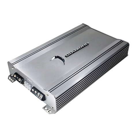
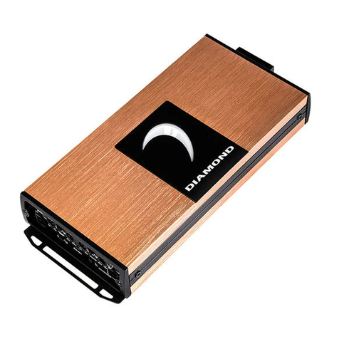
INPUT CONNECTIONS AND AUDIO CONTROL
The following figuresshow the input/audio control end panelsfor each amplifier along with
a key toshow the layout.
1.RCA lnput jacks
2.Gain Control
3.Bass Boost Control
4.Crossover Frequency
5.X-Over Mode Switch
6.RCA Output Jacks
7.Power lndicator
Fig.3 D3 400.2
1
23456
Fig.4 D3 400.4
1
23456
7 8 9 10
1.Front RCA lnputjacks
2.Rear RCA lnputjacks
3.Front Gain Control
4.Rear Gain Control
5.Bass Boost Control
6.Channel lnput Selector
7.Front X-Over FrequncySelection
8.Front X-Over Mode Switch
9.Rear X-Over FrequncySelection
10.Rear X-Over Mode Switch
11.Power lndicator
Gain Control Allows the nominaloperating level of the amplifier tobe set in conjunction
with the levelof input voltage from the sourceunit. The D3amplifiers will accommodate
low level (RCA)input ranging from 500 mV~5 V.
Bass Boost Acts like anequalizer with an adjustable gain fixedat 45 Hz. This adjustment
gives you upto 18 dB of boost atthat frequency. This can beused to compensatefor lack
of low-frequency responsein the car audio environment.
Crossover Frequency Selection The crossover frequencyis fully adjustable between
55 Hz and550 Hz.
Crossover Mode Switch Switches crossover betweenoff, low-pass, orhigh-pass.
When in theLP or HPposition, a 12dB per octave slope is implementedat the frequency
selected on theFrequency Knob.
Input Mode Switch Sets the inputmode of the amplifier, dependingon its purpose in the
system. Can beset to Stereo Mode, Bridged Mode,or Mono Mode.
Rear Channel InputSelect (4 channel only) Allows channels 3& 4 to use either setof
inputs (front orrear) for signal.
Problem
No AudioOutput
Solution
Low or noturn-on voltage. Check remote connections atamp and head unit.
Check remote voltageat amp with multi-meter, thereshould be around 12 volts when
head unit ison.
SETTING THE GAIN
The best wayto set thegains on any amplifier is withan oscilloscope and test tone. Using
the scope willensure the amplifier is not clippingand protect your system from beingdamaged
from being overdriven. If you havean oscilloscope and need help usingit, feel free to call DAT
TechnicalSupport for help.
Another wayis with a multi-meter and testtone. Set the multi-meter to DCvoltage, play
the test toneat 75% volume. Tune gains up until DCvoltage is present, then back thegains back
down a little.
If an oscilloscope,multi-meter, or test tone isnot available, find out the outputsignal
voltage of thehead unit. Match the gain knobwith that amount of voltage. Itshould be
between 500 mVand 5 V. If it is above 5V, the head unit has too muchsignal and the amp will
clip even withthe gain set at minimum. Turn system onand volume to 75%, if thereis
noticeable distortion, gainsshould be tuned down some.
SETTING THE CROSSOVER
Select LP orHP using theCrossover Mode Switch,select desired frequency by turning the
Frequency Knob.
SETTING THE BASS BOOST
If there isa noticeable lack of low endfrequency, thebass boost can be used toraise the
level of bassin the system. Turn the system on tonormal listening levels and raise thebass boost
until the levelof bass is satisfactory.
Caution: If "popping", "crackling" ,or any other unusualnoise is heard from the system
when using thebass boost, immediately turn the boostdown to avoid damaging components
in the system. Also, ifthe bass sounds "muddy" or distorted,turn the bass boost down.
TROUBLESHOOTING
Blown Fuse. Checkboth main system fuse and amplifier fuse. If blown,replace with
fuse of sametype and rating.
Speaker lead shorted. Check all speaker wire to makesure they are not shorted out
somewhere.
Blown speakers. Check speaker impedance with multi-meter, if the woofer isblown,
it will reada dead short.
Problem
Amplifier cycleson and off.
Solution
Thermal protection circuitsare shutting the amplifier off. Checklocation of amplifier
for adequate ventilation. Check impedance at amplifier for correctload. Check
voltage at amplifierfor low voltage.
Loose Connections. Check all power and signal wires to make sure theyhave solid
connection.
7
11
34
