Diamond D117E/7 User manual

Mod: D117E/7
Production code: T101BESN
06/2017


DISHWASHER INSTRUCTIONS MANUAL
MDIISY31-(r01) Page 1 of 21
UK
INDEX
CAP 1
FOREWORD ...............................................................................................................2
CAP 2 HANDLING AND TRANSPORTING THE MACHINE ..................................................2
TRANSPORTATION AND PACKAGING ....................................................................................2
HANDLING.........................................................................................................................22.2
STORAGE .........................................................................................................................32.3
DIMENSIONS .....................................................................................................................32.4
CAP 3 INSTALLATION ..........................................................................................................3
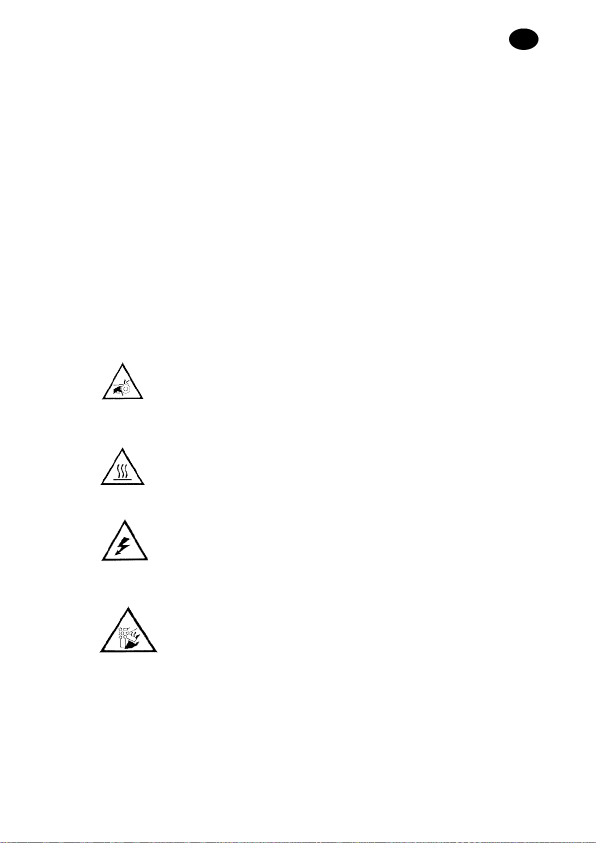
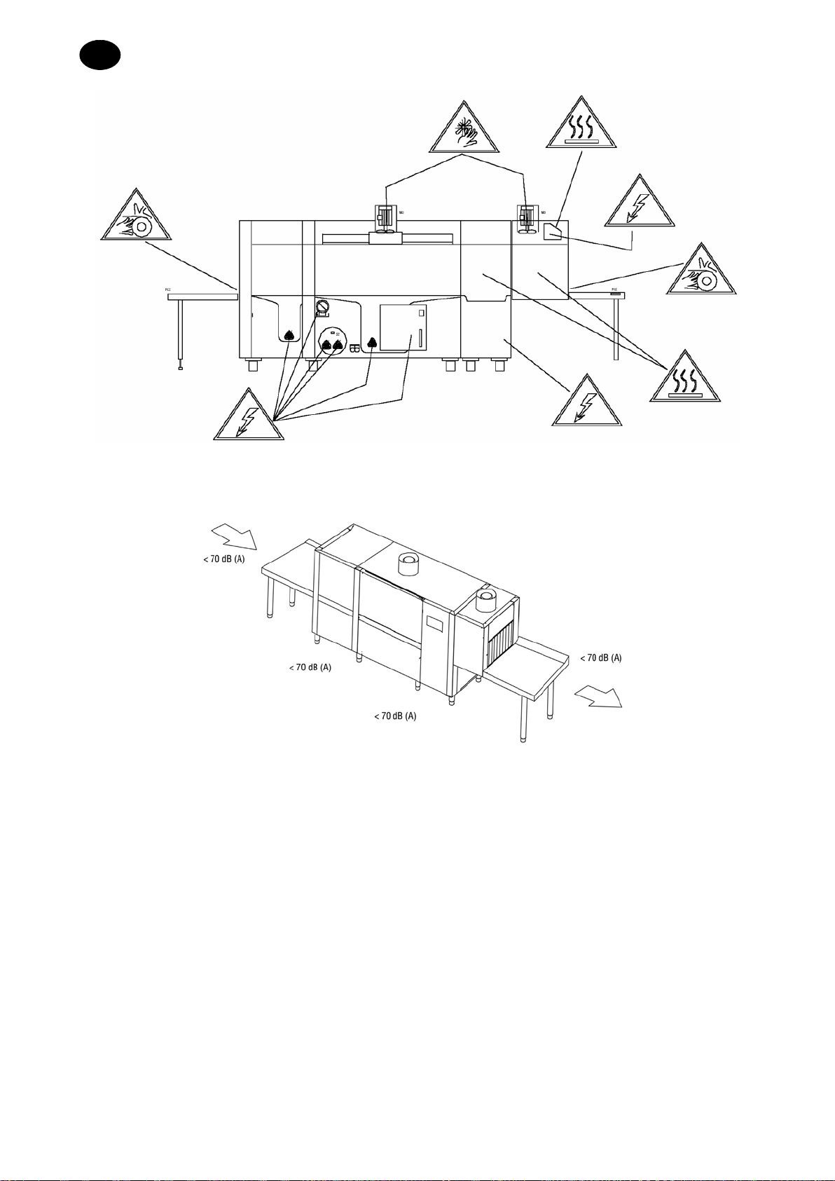
DANGER ZONES ................................................................................................................33.1
ACOUSTIC PRESSURE LEVEL ..............................................................................................43.2
UNPACKAGING AND POSITIONING........................................................................................53.3
ENVIRONMENTAL CONDITIONS............................................................................................53.4
CAP 4 INSTALLATION ..........................................................................................................5
ELECTRICAL CONNECTIONS................................................................................................54.1
HYDRAULIC CONNECTION...................................................................................................64.2
CONNECTION TO THE WATER DISCHARGE GRID....................................................................74.3
CONNECTING THE LIMIT SWITCH .........................................................................................74.4
INSTALLATION OF DISPENSERS...........................................................................................84.5
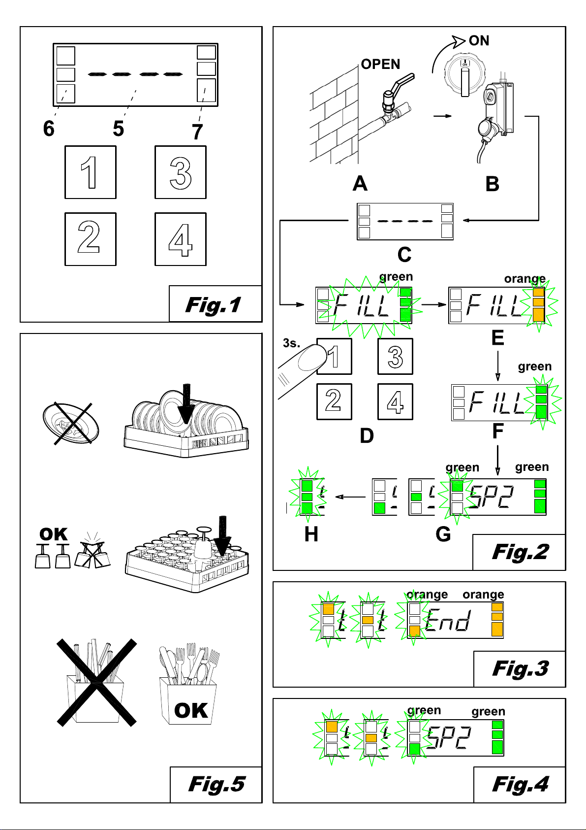
COMMISSIONING...........................................................................................................84.6 4.6.1 First boiler charging.....................................................................................................8
CONTROLS .......................................................................................................................84.7
RECOMMENDATIONS ON THE SAFETY REGULATIONS TO BE ADOPTED ..................................104.8
CAP 5 MACHINE DESCRIPTION.........................................................................................11
MACHINE DIAGRAM..........................................................................................................115.1
DANGEROUS POINTS .......................................................................................................125.2
SAFETY DEVICES.............................................................................................................125.3
USE ACCORDING TO THE REGULATIONS ............................................................................125.4
CAP 6 MACHINE USE .........................................................................................................13
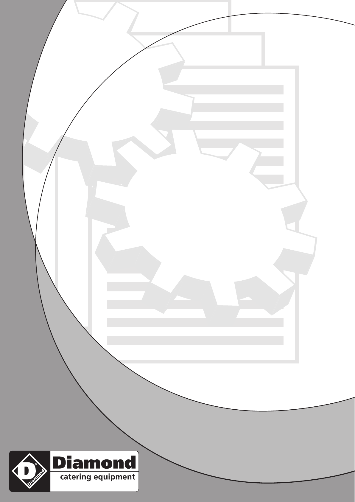
COMMAND DESCRIPTION..................................................................................................136.1
MACHINE START..............................................................................................................136.2
HEATING.........................................................................................................................136.3
WASHING........................................................................................................................136.4
WASHING PROGRAMME....................................................................................................136.5
STOP DEVICE ..................................................................................................................136.6
TEMPERATURE AND WORKING HOURS DISPLAY..................................................................146.7
LIMIT SWITCH DEVICE.......................................................................................................146.8
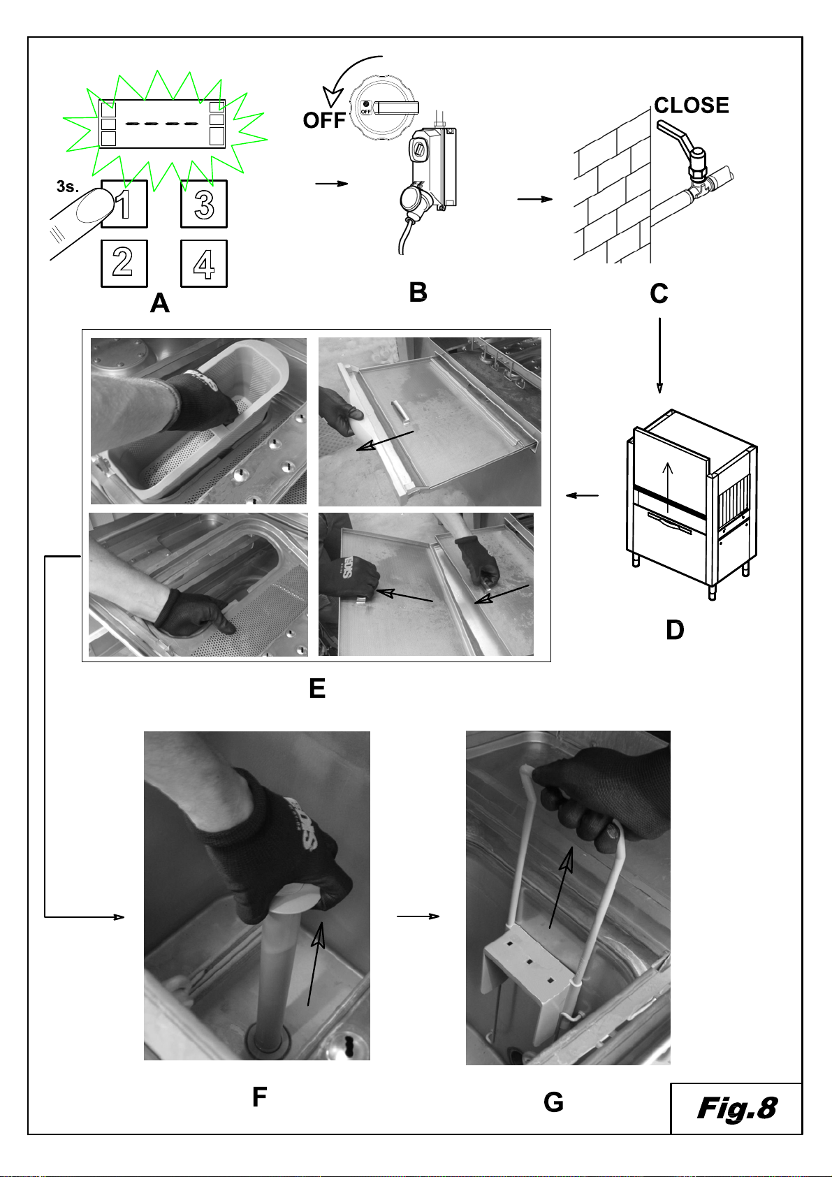
REGULATIONS.................................................................................................................146.9 6.9.1 temperatures .............................................................................................................14
6.9.2 dispensers.................................................................................................................15
USER MESSAGES.............................................................................................................166.10
FUNCTION AND STATUS BARS...........................................................................................166.11
SELF-DIAGNOSIS .............................................................................................................166.12
END OF WASHING OPERATIONS ........................................................................................186.13
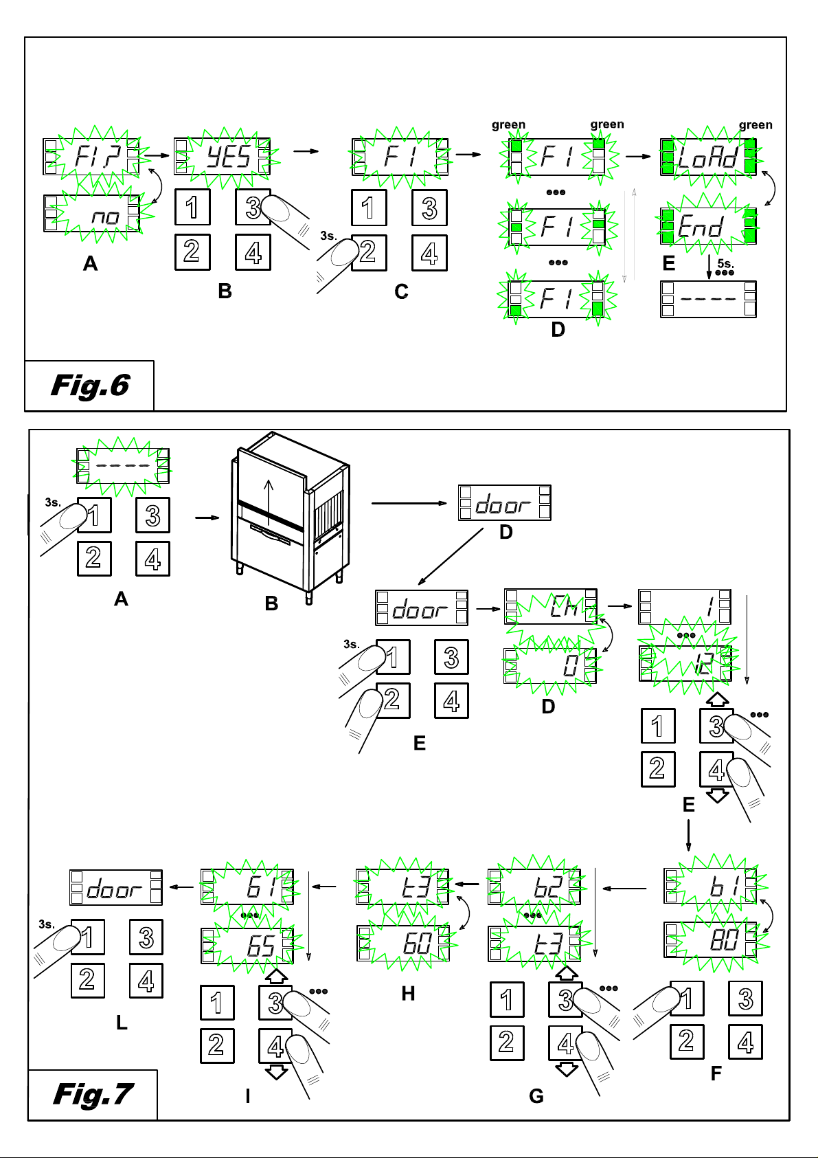
POSITIONING THE DISHES.................................................................................................186.14
CAP 7 MAINTENANCE........................................................................................................19
GENERAL RULES .............................................................................................................197.1
PERIODICAL MAINTENANCE..............................................................................................207.2
CAP 8 DISPOSAL................................................................................................................21
CAP 9 ENVIRONMENT........................................................................................................21

DISHWASHER INSTRUCTIONS MANUAL
Page 2 of 21 MDIISY31-(r01)
UK
Cap 1
FOREWORD
The contents of this manual supply important safety information throughout the
various phases of installation, use and maintenance.
Failure to follow the instructions contained in the attached documentation may
compromise the safety of the appliance and immediately annul its warranty.
Warnings:
Carefully store all the documents near the appliance. Hand them to the technicians and workers in
charge of use and make sure they are
kept well preserved over time, at a safe location, ideally with
copies for frequent consultation.
The operator must read, understand and learn the present manual before carrying out any
operation on the device.
This piece of equipment is destined exclusive
ly to the professional washing of tableware for large
numbers of people. Therefore, its use and maintenance are only to be carried out by well-trained
personnel, committed to following the manufacturer's instructions.
Warranty:
The manufacturer declines
all responsibility and warranty for damages to things or persons derived from
failure to follow the instructions provided herein or from improper use of the machine.
Failure to follow the indications contained in the attached documents may compromise the safety of the
device and cause the warranty to be immediately annulled.
Installation and repairs carried out by unauthorised technicians, or the use of non-original spare parts,
will cause the warranty to be immediately annulled.
Cap 2 HANDLING AND TRANSPORTING THE MACHINE
Transportation and packaging
The machines can be transported in two manners:
- on lorries
- in containers
Both situations require the same kind of packaging.
Handling
2.2
•The machines must be handled with care, using a forklift truck or a hand
pallet truck.
•The hoisting points are marked on the machine by adhesive labels.
•During transportation, it is forbidden to remain near the machine, as it
may tilt and cause serious harm to persons nearby.
•Accidents may involve impact, entanglement, and trapping by the
machine during handling and storage of the machine itself.

DISHWASHER INSTRUCTIONS MANUAL
MDIISY31-(r01) Page 3 of 21
UK
Storage
2.3
Storage methods for materials must include pallet, containers, conveyor belts, vehicles, lifting
equipment and devices suitable for the prevention of damages caused by vibration, impact, abrasion,
corrosion, temperature or any other condition that may occur. The parts stored must be periodically
inspected for deterioration.
Storage:
Transportation and deposit: between -10° C and 55° C, with peaks of up to 70° C (max 24 hours)
Dimensions
2.4
The machines of the rack conveyor line are available in various models, whose layouts are attached to
this document, including the dimensions of each machine.
Cap 3 INSTALLATION
Danger zones
3.1
Definition of danger zone and how (see figures on the next page) hazards may occur; general
description of the protection measures adopted.
Risk of entangling and dragging
- On the conveyor
High temperature hazard
- on the doors that give access to the washing/rinsing areas
- on the walls of the drying area
- on the boiler, during installation and maintenance operations
Dangerous voltage
- general switchboard
- electro-pump
- fan
- electric resistances
Shearing hazard
- on the fan of the suction unit
The machine is equipped with bulkheads that limit access to the inner part of the machine and to
moving parts. The bulkheads are fixed by screws.
MOVING PARTS
HOT
DANGEROUS POWER
VOLTAGE

DISHWASHER INSTRUCTIONS MANUAL
Page 4 of 21 MDIISY31-(r01)
UK
Acoustic pressure level
3.2

DISHWASHER INSTRUCTIONS MANUAL
MDIISY31-(r01) Page 5 of 21
UK
Unpackaging and positioning
3.3
When the machine is received, open the packaging and check the machine and its accessories for
damage occurred during transportation. If any damages are detected, immediately report to the
transportation company and do not proceed with installation: seek the assistance of qualified,
authorised personnel.
The manufacturer cannot be held responsible for any damage occurred during transportation.
Packaging elements (plastic bags, Styrofoam, strips of wood, nails etc) must be kept away from the
reach of children, as they are potentially hazardous.
Position the machine according to the indications supplied by the general
installation layout, supplied separately, making sure its position is correct
regarding maintenance needs.
Screw the feet to the supports and place the machine in its proper position.
Adjust the height of the feet to level the machine. As these machines are long,
use a spirit level.
Warning:
While positioning the machine, do not drag it on the floor, as this may damage its
structure.
The floor must be dimensioned taking into consideration the overall weight of the
machine. The floor must be levelled.
Environmental conditions
3.4
•Environmental temperature: 40° C max/4° C min (average: 30°C)
•Altitude: up to 2,000 metres
•Relative humidity: Max 30% at 40° C/max 90% at 20° C
Cap 4 INSTALLATION
Electrical connections
4.1
•Caution! Installation must only be carried out by specialised
technicians!
•Prior to connecting the equipment, make sure that both the
voltage and frequency of the power grid correspond to those
indicated in the information plate on the lateral panel of the
machine.
•It is obligatory to connect the machine to the power grid by means
of a dedicated omnipolar switch, in conformity with the safety
regulations in force, of the automatic type, with fuses with at least
3 mm of opening between contacts. The above mentioned
switch, not supplied with the machine, must be installed on the
wall, in such a position that it can be easily reached, at a height
between 0.6 and 1.7 m.
•Prior to connecting the machine to the power grid, make sure the
power supply line is not live.

DISHWASHER INSTRUCTIONS MANUAL
Page 6 of 21 MDIISY31-(r01)
UK
•Remove the anterior panel and the protection of the switchboard
by loosening the screws.
•Introduce the power cable through the cable gland.
•Connect the cable to the terminals on the board, as indicated in
the wiring diagram attached.
•If the Neutral and Earth cables are connected incorrectly, the
machine may suffer irreversible damage, and the warranty may
be annulled!
•Check that the cables on the contactors, thermal protections etc
are well tightened, as the screws may have loosened during
transportation.
•Place the anterior panel back in position and the control panel,
using the screws included.
•The power supply cable, exclusively of the H07RN-F type, must never be tensioned or crushed
during normal use or routine maintenance.
•In addition, the machine must be installed as part of an equipotential system,
connected through a screw marked with the symbol .
•The equipotential conductor must have a section of 10 mm
2
.
It is forbidden to use multiple sockets, adaptors, cables of unsuitable type or section, or with
extension junctions not in conformity with the current regulations regarding electric systems.
Hydraulic connection
4.2
Prepare the area according to the installation diagram attached.
Prior to connecting the machine, make sure that there is a gate valve installed
between the water mains and the machine, to make it possible to interrupt
water supply in case of need or when carrying out repairs.
In addition, make sure that the supply capacity is not inferior to 20 l/min.
Make sure that the incoming water temperature and pressure
correspond to the values indicated in the technical characteristics tag.
If the water is harder than the value indicated in the tag, it is advisable to
install a water softener uphill to the power supply solenoid valve of the
machine.
If the concentration of residual minerals in the conductibility water is very
high, it is advisable to install a demineralisation system calibrated to obtain a
residual water hardness compatible with the values in the table below.
WARNING! High concentrations of sodium chloride may cause rust.

DISHWASHER INSTRUCTIONS MANUAL
MDIISY31-(r01) Page 7 of 21
UK
Characteristics Min Max
Hardness
French hardness
f
5
10
German hardness °dH
4
7.5
English hardness °e
5
9.5
Residual
minerals Parts per million ppm
70
140
Maximum mg/l 300/400
Connection to the water discharge grid
4.3
•Conveyor belt dish washing machines operate continuously. This
means they require particularly efficient and well-working discharge
systems.
•For information on the position of the discharge outlets, please
refer to the installation diagram attached.
•Connect the discharge outlets of the machine to the mains, using
tubes resistant to continuous temperatures of 70° C.
•Use the discharge tube and the connection supplied with the
machine.
•The discharge system must include a siphon.
Connecting the limit switch
4.4
It is OBLIGATORY to install a limit switch in order to use the
machine.
•The limit switch must be installed on the outgoing plane.
•The switch must be mechanically fixed to the machine in a
manner suitable for its application.
•It is advisable to use a limit switch with lever activation with
washer, to increase contact surface and reduce the effect of
mechanical contrast.
•It is obligatory to verify its proper functioning with all the baskets
in use in the area.
•It must have a protection of at least IP55.
•The switch must be in its positive mode (contact normally closed).
•Its minimum rated capacity must be 240 V 1.5 A.
•The advised mechanical duration is 10,000,000 cycles.

DISHWASHER INSTRUCTIONS MANUAL
Page 8 of 21 MDIISY31-(r01)
UK
Installation of dispensers
4.5
The machine is equipped with specific outlets for the dispensers for rinse aid and dish washing liquid.
Connect the dispensers according to the wiring diagram, to ensure that the machine works properly.
Both the rinse aid and the washing liquid must be dosed by the automatic dispensers.
The amount of both products is established by the installation technician, according to water hardness.
The technician
is responsible for calibrating the dispensers.
For the initial filling of the dosing circuit and for its relative regulations, please refer to the "Regulations"
paragraph.
•The level of liquids in the containers must never be allowed to drop to empty levels.
•The dispensers must never be filled with corrosive or soiled products.
•It is forbidden to use chlorine-based products, as they cause the formation of chlorine; in
concentrations above 50 ppm, they may lead to corrosion.
•It is not advisable to dispense the products manually.
•For any other installation, please refer to the wiring and installation diagrams attached.
•The machine does not support multi-voltage dispensers and/or with more than 5 A of absorption per
outlet.
If you decide to use this kind of dispenser, it must be connected to an external 16 A relay.
COMMISSIONING
4.6
4.6.1 First boiler charging
Reference: Figures 2 and 6
•Open the gate valve of the water supply system (Fig. 2/A)
•Supply the machine with power by switching on the main switch (Fig. 2/B)
•The display will show 4 horizontal bars (Fig. 2/C)
•Press the line button (1) to switch the machine on. (Fig. 2/D)
•The display will show the alternating message “FI?” “no” (Fig. 6/A)
•Press button (3) to select “yES” (Fig. 6/A)
•To confirm, press button (2). (Fig. 6/C)
•The machine will automatically start loading the boiler, and the display will show the message “FI”
(Fig. 6/D)
•When the display shows the alternating messages “LoAd” “End”, it means the loading phase is
concluded, and the machine is ready to be switched on. (Fig. 6/E)
Controls
4.7
•Make sure that the level of water in the washing tank, once filled, is 1-2 cm below the overflow
level.
•Make sure that the temperature of the washing and rinsing tank is in accordance with the
settings.
•Check the dispensers for proper function.
•Make sure the rinsing economiser is working well: it must start dispensing hot water as soon as
a basket arrives beneath the rinsing jets, and make the hot water flow stop when the basket
moves away.
•Make sure the limit switch is working. The switch must block the functioning of the advancement
motor and of the pump whenever a basket reaches the end of the plane. Once the basket is
removed, the functioning must resume.
•Check the rotation direction of the pumps. If they are turning in the opposite direction, invert the
two phases of the power supply cable.

DISHWASHER INSTRUCTIONS MANUAL
MDIISY31-(r01) Page 9 of 21
UK
•Check the regulation of the mechanical safety system of the conveyor,
which must be adjusted taking into account the overall length of the
machine and of the output tables measured by themselves.
A full load of baskets full of plates should not block the advancement
of the conveyor.
To make the regulation, turn the screw on the bracket that supports
the conveying motion unit.
The advised L length must range from 60 to 75 mm (see figure).
Please contact your assistance centre for complex applications.
•Make sure that the rotation direction corresponds to the figure and to
the central motion of the conveyor.
WARNING: The mechanical safety will not work efficiently if the
rotation direction is incorrect.
•Check the manometer during rinsing. If necessary, adjust the pressure regulator and set the value
as indicated in the table:
Version
Litres/hour
Baskets/hour
bar
No pre-wash
160
0.6
With pre-wash
270
0.7
Failure to carry out these checks will automatically annul the warranty.
END OF INSTALLATION
•The installation technician must inform the manufacturer in case of functioning and/or safety
anomalies observed during the initial testing.
•The machine can only be used once installation is complete.
•The technician must issue a declaration of work carried out according to the rules of the trade and
to the laws in force.

DISHWASHER INSTRUCTIONS MANUAL
Page 10 of 21 MDIISY31-(r01)
UK
Recommendations on the safety regulations
4.8 to be adopted
•This machine must only be destined to the use for which it has been expressly designed. Any other
use must be considered improper and therefore dangerous.
•Do not leave the machine exposed to atmospheric agents (rain, sun etc).
•Do not allow the machine to be used by children or mentally disabled persons.
•The machine must only be used by trained personnel.
•
Keep the machine in perfect functioning conditions and always use the several protections it is
equipped with; ordinary maintenance must be performed by professionally qualified personnel. In
particular, all safety devices must be periodically inspected by the maintenance technician.
•Prior to connecting the machine, make sure the information on the plates corresponds to the
information regarding the power and water grids.
•Make sure the machine is perfectly earthed, as defined by the current laws in force. This
fundamental safety requisite must absolutely be respected. In case of doubt, request an accurate
inspection of the entire machine by professionally qualified personnel.
•Make sure that the power capacity of the system is suitable for the maximum power absorbed by the
machine. In case of doubt, seek the assistance of a qualified person, who must make sure that the
section of the system cables is suitable for the power absorbed by the device.
•The incoming power grid cables (not included) for the main switch must be suitably marked for
danger.
•The power cable of this machine must be of the H07RN-F type.
•Prior to carrying out any maintenance operation, cut off power from the machine using the power
switch.
•In case of malfunctioning, switch off the main power switch and do not attempt any direct repair
intervention.
•The machine must only be repaired by the manufacturer or by an authorised assistance centre,
using only original parts.
•Failure to follow these indications may compromise the safety of the machine.
•Do not use water to extinguish fires on the electric parts. Use a powder fire extinguisher.
•The machine must not be left under voltage when not in use.
•Do not modify the protections, and only remove them if the machine is not working and is cut off
from the power supply.
•If you decide not to use a machine of this kind any longer, it is advisable to make it impossible to use
by removing its power cable, after unplugging it from the mains.
•When cleaning the machine, strictly follow all the instructions supplied in the manufacturer's booklet.
•Do not obstruct the aspiration or dissipation grids.
•Do not operate the machine without its filters.
•After cutting off the machine from the power supply, only qualified personnel may access the control
board.
•Do not submerge your unprotected hands in the water-detergent mixture. In case of accidental
contact with the eyes, rinse with abundant clean water and seek medical advice.
•Do not open the doors too quickly. Wait at least 15 seconds after the engines have stopped.
•When opening the doors, make sure they are well hooked to their supports.
•Should the conveying system stop due to the safety device, remove the obstacle that cause the
block before resuming operation.
•Make sure that the objects being washed are dishwasher-safe.
•Do not use dispensing devices or other devices not intended by the manufacturer, which may alter
the safety or functionality characteristics of the machine.
•Use only anti-foam detergents specific for dishes, in the doses recommended by the manufacturer,
according to the hardness of the water and the capacity of the tank.
•It is forbidden to use acid or corrosive products to clean the machine or to wash the dishes.
•NEVER use chips, steel wool or steel brushes to wash stainless steel items.
•In order to protect the environment, we advise against the use of corrosive or polluting products. Do
not exceed the recommended dose.

DISHWASHER INSTRUCTIONS MANUAL
MDIISY31-(r01) Page 11 of 21
UK
•The personnel in charge of handling the dishes must absolutely follow the hygiene regulations in
force after the washing.
•To pick up an object that fell inside the machine, stop the machine and switch it off.
•Do not get near the moving parts with dangling jewellery or loose sleeves, to avoid tangling.
•Do not use the machine as support surface for objects or tools.
•Always switch the machine off when not in use, using the wall-mounted omnipolar switch.
•Cut off water supply every time the machine is not in use.
•Immediately switch the machine off if any water leaks are detected.
•Keep in mind that the machine must never be used without its protection curtains (entrance, exit,
and intermediary positions).
•It is forbidden to remove the basket from the machine before the basket is completely out of the
machine.
Cap 5 MACHINE DESCRIPTION
Machine diagram
5.1
1 Pre-wash chamber 5 Final rinsing chamber 9 Washing tank
2 Washing chamber 6 Drying chamber 10 Rinsing tank
3 Pre-rinse chamber 7 Steam extraction and recovery zone 11 Boiler
4 First rinse chamber 8 Pre-wash tank
Conveying belt washing machines are manufactured with high-quality materials: AISI 304 stainless steel
for the washing tanks and stainless steel for the remaining parts.
•In section 1 (pre-wash), the dishes are submitted to an initial removal of dirt.
•In section 2 (wash), the dishes are actually washed.
•Rinsing takes place in sections 3-5.
•The dishes are dried in section 6.
•In section 7, steam is extracted or heat is recovered.
•The baskets are automatically conveyed through the sections thanks to a lateral conveyor.

DISHWASHER INSTRUCTIONS MANUAL
Page 12 of 21 MDIISY31-(r01)
UK
Dangerous points
5.2
A dangerous point or dangerous area of the machine is an area in which accidents may occur in case of
failure to follow the instructions.
•
If the conveyor stops during regular functioning, press the line button. Only restart the machine once
the cause of the blockage has been identified and removed.
•
It is forbidden and very dangerous to access the internal part of the machine from the entrance or exit
of the conveyor when the machine is on and in motion.
•
It is forbidden and very dangerous to make repairs to the conveying system and to the electric users
when the machine is working.
•
It is forbidden to use the machine without the surveillance of an operator.
•
Do not submerge your hands in the water in the tanks.
•
It is forbidden to access the switch to deactivate or activate the machine with wet hands.
•It is absolutely forbidden to access the internal part of the electric box.
Safety devices
5.3
•
On the doors there are magnetic switches that interrupt pre-
wash, wash, rinse and basket conveying,
when opened.
•
Protection against unexpected start-
up. If the machine accidentally stops due to lack of electricity, it
will not resume automatically when the power returns.
•
Thermal protections for electro-pumps and motors, guaranteeing their integrity in case of short-circuit
and overload.
•
Magneto-thermal protections or fuses for each heating element, protecting elements from the dangers
of short-circuits and overload.
•
Boiler safety thermostat. In case of malfunctioning of a thermostat for temperature control, a second
safety thermostat will intervene and interrupt the functioning of heating elements.
•
Safety microswitch on the conveyor. If the conveying stops due to accidental causes, the microswitch
installed near the support of the motor reducer will interrupt the conveying function.
•
Safety door stop. When the doors are opened, the hooks prevent them from falling if a spring should
break.
•Low-voltage commands.
Use according to the regulations
5.4
•
Conveying machines are expressly designed to wash dishes, glasses, cups, flatware and similar
items together with the basket in which they are placed. Any other use is considered to be not in
accordance with the regulations.
•
It is imperative to respect the manufacturer's safety, use and maintenance regulations.
•
It is imperative to respect the suitable regulations to prevent accidents, and further acknowledged
safety technique regulations.
•
The machine must only be used by personnel suitably trained to avoid hazards.
•The machine must only be used with original manufacturer's accessories and spare parts.

DISHWASHER INSTRUCTIONS MANUAL
MDIISY31-(r01) Page 13 of 21
UK
Cap 6 MACHINE USE
Command description
6.1
With reference to Fig. 1
1
ON/OFF LINE BUTTON
5
INFORMATION DISPLAY
2
START/STOP BUTTON
6
FUNCTION BAR (LED)
3
PROGRAMME SELECTION BUTTON
7
ALARM BAR (LED)
4
SPECIAL PROGRAMME SELECTION BUTTON
Machine start
6.2
Reference to Figure 2
•Open the gate valve of the water supply system (Fig. 2/A)
•Supply the machine with power by switching on the main switch (Fig. 2/B)
•The display will show 4 horizontal bars (Fig. 2/C)
•Press the line button (1) to switch the machine on. (Fig. 2/D)
•The display will flash the message “FILL” and the machine will start loading water (Fig. 2/E).
•Once the proper level has been reached, the display will show the default message “SP2”. (Fig. 2/G)
Heating
6.3
Reference to Figure 2
•Once the loading is finished, the machine will automatically start heating.
•During heating, the LED function bar (6) is orange (Fig. 2/G).
•As soon as the pre-set temperature is reached, the LED function bar (6) will turn green and fixed.
(Fig. 2/H)
Washing
6.4
Reference to figure 4
•To start washing, simply insert a basket at the the entrance of the machine until it is hooked by the
basket conveying system.
•The LED function bar (6) will then start moving.
•During washing, the display will show the washing programme being used.
Washing programme
6.5
Use the keyboard to select the following programmes:
standard programmes selected using button (4)
•SP1 “High capacity “, to wash dishes with light, fresh dirt.
•SP2 “General purpose”, programme for general use.
programmes selected using button (3)
•AP1 “Prolonged contact” ensures a longer washing time, in accordance to regulation DIN 10534
•AP2 “Glass” programme, specific for the washing of glasses.
It is only possible to select a different programme during washing after pressing button (2).
Stop device
6.6
The machine is equipped with a ON/OFF line button (1) on the control board, and its use causes the
immediate stop of all moving parts and of the washing programme.
It is possible to install additional optional stop devices near the entrance and the exit of the baskets.

DISHWASHER INSTRUCTIONS MANUAL
Page 14 of 21 MDIISY31-(r01)
UK
Temperature and working hours display
6.7
It is possible to visualise washing and rinsing temperatures at any moment.
Simply keep button (2) pressed for a few seconds.
The display will show, in sequence, the washing temperature “t”, the rinsing temperature “b”, and the
machine hours of work “Hr”.
The message is displayed twice.
Limit switch device
6.8
The machine must work with a limit switch installed on the exit plane of the baskets (see installation
chapter).
The display will show the message “End” when a basket exiting the machine reaches the end of the
plane, and the conveyor stops until the basket is removed (Fig. 3).
Simply remove the basket from the end of the plane to restart the machine completely.
If the basket is not removed within a few minutes, the machine will switch off, in a succession, the rinsing
area, the washing area, the pre-wash area and, finally, the drying area, when installed.
Regulations
6.9
It is possible to regulate the temperature and the dispensing times.
With reference to Figure 7
•
Switch the machine off by pressing the line button (1) (Fig. 7/A)
•
Open the door of the machine (Fig. 7/B)
•
The display will show the message “door” (Fig. 7/C)
•
Keep buttons (1) and (2) simultaneously pressed for a few seconds. (Fig. 7/D)
•
The display will alternate messages “CH” and “0”.
•
Scroll through the numbers using buttons (3) and (4) until you reach “12”. (Fig. 7/E)
•
Press line button (1) (Fig. 7/F).
•
Select the parameter you wish to regulate by scrolling through the list with buttons (1) and (2) (Fig.
7/G).
•
The display will show, in sequence, the parameter and the set value (Fig. 7/H).
•
Use buttons (3) and (4) to set the desired value. (Fig. 7/I)
•
Once all regulations are concluded, keep the line button (1) pressed for a few seconds.
•The new settings are now memorised and the display will show the message “- - - -” . (Fig. 7/M)
6.9.1 temperatures
It is possible to set the washing and rinsing temperatures of all washing programmes, with the exception
of the Glass programme.
Parameter
Programme rinsing temperature
range of regulation (° C)
b1
“SP1”
“oFF”,1,2…90
b2
“SP2”
b3
“AP1”
Parameter
Programme washing temperature
range of regulation (° C)
t1
“SP1”
“oFF”,1,2…70
t2
“SP2”
t2
“AP1”

DISHWASHER INSTRUCTIONS MANUAL
MDIISY31-(r01) Page 15 of 21
UK
6.9.2 dispensers
It is possible to adjust the dosing time, in seconds, for the rinse aid and detergent dispensers.
Parameter
Dosing time
range of regulation (s)
dt
detergent
oFF,1,2…25
bL
rinse aid
oFF,1,2…25
It is possible to manually load the dosing circuit.
Proceed as follows:
•Select, from the menu, parameter “bn” if you wish to load the rinse aid circuit, or “dn” if you want to
load the detergent circuit.
•The display will show, in succession, “bn”, “oFF” , if you selected the rinse aid circuit, or “dn”, “oFF”
if you selected the detergent circuit.
•Keep button (3) pressed.
•The corresponding dispenser will start loading the circuit and the display will show “on” instead of
“oFF”
•To stop the dispenser, simply release button (3).
This manual suits for next models
1
Table of contents
Other Diamond Dishwasher manuals

Diamond
Diamond 046D-NP User manual

Diamond
Diamond DCS9 User manual

Diamond
Diamond DK7/2-NP User manual

Diamond
Diamond DC502/6M-PS User manual

Diamond
Diamond 914791 User manual

Diamond
Diamond 051D/6M-PS User manual

Diamond
Diamond DK7/6 User manual

Diamond
Diamond DFE8/6 Operating and installation instructions

Diamond
Diamond DC402/6-PS User manual

Diamond
Diamond Diverso WR-LV50-MC User manual