DIC SEPAREL PF Series User manual

www.separel.com/en
Instruction Manual for
SEPAREL PF Modules
Hollow Fiber Membrane Module
Before using the SEPAREL® PF series, be sure to read this instruction manual to ensure safe and
proper use.
DIC will not have any liability to a customer or end user in connection with any costs and damages
arising directly or indirectly from any defective modules.
We are not responsible for any usage, installation, or any other handling done by the customer.
The module must be used, installed, and handled responsibly by the customer.
PF (Internal Perfusion Flow) Series
؞PF-001D Series
؞PF-004D Series
؞EF-015 Series
؞EF-030 Series
PF-001D PF-004D PF-015 PF-030
Ver. 1. 2
June 3, 2016
Application Materials Product Division

Ṳ
Ṳ
About this Instruction Manual
This instruction manual explains how to handle SEPAREL® PF degassing modules, such
as the PF-001D, PF-004D, PF-015, and PF-030 series, with precautions to be followed
for your safety.
Before using the SEPAREL® PF series, be sure to read this instruction manual to ensure
safe and proper use.
Depending on use conditions, proper methods for usage and storage may differ even
though there are descriptions about usage methods, storage methods, and risks
associated with the product module within this manual.
Please note that this manual does not describe all information about risks related to
usage and storage of the product.
Although the content of this instruction manual is based on reliable testing and
measurement results, no guarantees are provided for its accuracy.
DIC does not have any responsibility for anything described or not described in this
manual.
The details of this instruction manual may be modified for improved reliability of the
SEPAREL® PF series or to account for changes in its design.
2
2
Application Materials Product Division
INSTRUCTION MANUAL

ṲWarranty, Warranty Period
ẔWarrantyẕ
At the time of delivery, DIC warrants that the Separel module will be free from defects in material and
workmanship and meet the specifications supplied to the customer by DIC.
ẔWarranty Period ẕ
The following Warranty Period is applied only if customer use of the Separel module is in accordance with the
instructions contained in this manual, the specification sheet, any applicable Cleaning Guides and the Warranty
Statement.
(1) Water
Maximum 12 months from the date of delivery of the module
- This warranty period is applied only if customer refers to P.11, 3-3 (1).
- The above warranty will be voided in the event that water of unspecified quality is used.
(2) Liquids other than water
- Water-Based Liquid : Maximum 12 months from the date of delivery of the module*1
- Non-Water-Based Liquid : Maximum 6 months from the date of delivery of the module*1
*1 The warranty periods shown above are strictly to demonstrate the maximum warranty period available for
the modules. Any actual warranty period will be based upon the results of compatibility tests of the module
with all liquids which may come in contact with the module. The compatibility testing procedures will be
informed to the customer by DIC. It is the customer’s responsibility to conduct the compatibility tests and
provide the results thereof to DIC. In accordance with the results of the compatibility test, any warranty period
will be determined through consultations between DIC and the customer. DIC and the customer will agree in
writing to the warranty period, as well as, terms of use for the module (“Warranty Statement”).
If a liquid other than water (2) is used, only several SEPAREL products are applicable—please refer to Table 1
below.
3
Model
Liquid
Ṟ
Ṟ
Water
ṟ
Liquids other than water
ί
Developing solution, Inkjet Inks and so on)*2
PF-001D series ṺṺ
PF-004D series ṺṺ
PF-015 series Ṻᶣ
PF-030 series Ṻᶣ
“․‒‾⁛ ⁛⁗⁖‒‒⁞⁛⁛⁖‒⁘‒⁚⁛⁕⁚‒⁘⁞⁛⁖‒⁕ ⁓⁛⁔⁛⁞⁛‒⁚⁓‒⁔⁗⁗‒⁗⁛⁘⁛⁗⁖†‒⁆⁚⁗‒⁂‸‟‸‒⁅⁗⁛⁗‒⁞⁛⁗⁖‒ ⁓‒⁓⁞‒⁔⁗‒⁗⁖‒⁘‒
‵⁚⁗ ⁛⁕⁓⁞‒⁓⁖‒⁅⁞⁗†
⁆⁓⁔⁞⁗ ‣ ‵⁗⁖⁗⁕⁗‒⁓⁔⁞⁗
INSTRUCTION MANUAL
Application Materials Product Division

Ṳ
Ṳ
Warranty Remedy
ẔWarranty Remedyẕ
During the applicable warranty period as specified in the Warranty Statement, any defective module
will be replaced free of charge by DIC in cases where a defect is found under normal use in
accordance with this instruction manual and under use and storage conditions specified in the
specification sheet and Warranty Statement.
This is the sole remedy available to the customer under this warranty. DIC will not have any liability
to a customer or end user in connection with any costs and damages arising directly or indirectly
from any defective modules.
We are not responsible for any usage, installation, or any other handling done by the customer. The
module must be used, installed, and handled responsibly by the customer. The above warranty will
be voided in the event that a liquid which has not been specified for use between the customer
and DIC, as specified in the Warranty Statement, is used in the module or by any other use,
installation or handling that is not in accordance with the instructions contained in this manual, the
specification sheet and Warranty Statement.
This module is consumable. DIC recommends that customers replace the module within the
warranty period.
4
4
Ṳ ᵰᶃᶅᵿᶐᶂᶇᶌᶅᴾᵰᶃᶎᶐᶍᶂᶓᶁᶒᶇᶍᶌᴾᵿᶌᶂᴾᵮᶆᶍᶒᶍᶁᶍᶎᶗᶇᶌᶅᴾᶍᶄᴾᶒᶆᶇᶑᴾᵫᵿᶌᶓᵿᶊ
Ṹ ᵰᶃᶎᶐᶍᶂᶓᶁᶒᶇᶍᶌᴾᶍᶄᴾᶒᶆᶇᶑᴾᶋᵿᶌᶓᵿᶊᴾᶇᶌᴾᶕᶆᶍᶊᶃᴾᶍᶐᴾᶇᶌᴾᶎᵿᶐᶒᴾᶇᶑᴾᶑᶒᶐᶇᶁᶒᶊᶗᴾᶎᶐᶍᶆᶇᶀᶇᶒᶃᶂᵌ
Ṹ ᵲᶆᶃᴾᶁᶍᶌᶒᶃᶌᶒᴾᶍᶄᴾᶒᶆᶇᶑᴾᶋᵿᶌᶓᵿᶊᴾᵿᶐᶃᴾᶑᶓᶀᶈᶃᶁᶒᴾᶒᶍᴾᶁᶆᵿᶌᶅᶃᴾᶕᶇᶒᶆᶍᶓᶒᴾᶌᶍᶒᶇᶁᶃᵌ
Ṹ ᵱᵣᵮᵟᵰᵣᵪ®ᶇᶑᴾᵿᴾᶐᶃᶅᶇᶑᶒᶃᶐᶃᶂᴾᶒᶐᵿᶂᶃᶋᵿᶐᶉᴾᶍᶄᴾᶒᶆᶃᴾᵢᵧᵡᴾᵡᶍᶐᶎᶍᶐᵿᶒᶇᶍᶌᵌ
INSTRUCTION MANUAL
Application Materials Product Division

5
Contents
1. General Precautions P. 6
2. Upon Receipt P. 6
3. Installation P. 7
4. Start-Up P. 11
5. Shutoff and Storage P. 12
6. Restart P. 12
7. Maintenance P. 13
Reference Data
1. Basic Principles of Degassing P.14
2. Vacuum Pressure Degree P.15
3. Setting Value of Vacuum Pressure Degree P.16
4. Range of Liquid Flow Rate P.17
5. Inner Volume P.18
6. Troubleshooting P.19
Contacts P.22
5
Application Materials Product Division
INSTRUCTION MANUAL

1. BASIC PRECAUTIONS
2. UPON RECEIPT
6
6
1-1. Maintain use, handling, and storage conditions described in specifications.
1-2. SEPAREL is consumable. We recommend replacement within the warranty period.
1-3. We are not responsible for any usage, installation, or other handling done by the customer.
Make sure that the product is used, installed, and handled responsibly.
1-4. Do not feed the following liquids into SEPAREL–oxidizing agents (highly concentrated
chlorine water, ozone water, etc.), strong acids, strong bases, organic solvents, alcohol,
oils, or any other liquid which is not compatible with the liquid and materials that SEPAREL
modules are composed of.
1-5. Do not remove the end-cap of SEPAREL modules..
1-6. Do not shake or shock the module.
1-7. Protect the module from direct exposure to the sun.
1-8. Do not freeze the module.
1-9. Strictly maintain the quality of supplied liquid, temperature, and pressure based on the
specifications stipulated under the item number for each module.
1-10. Refer to the cleaning guidelines before cleaning with.
In cases where liquid that has not been deemed compatible by DIC is used,
no warranty will apply to the product.
2-1. Check the label and shape of the module to confirm that the type and series number
are the same as that of which you ordered.
2-2. Check whether no damage was sustained during transportation. If you find any
damage, notify your sales representative immediately.
2-3. Do not physically shock or shake the SEPAREL module during unloading or storage.
INSTRUCTION MANUAL
Application Materials Product Division

7
7
3-1. Place of Installation:
Install SEPAREL in accordance with conditions specified in the specification sheet,
⅐No exposure to direct sunlight
⅐No physical shock or shaking
⅐No contact with dust, moisture, corrosive gas, or liquid
⅐Easy access for maintenance, inspection, repair, and replacement
3. Installation
INSTRUCTION MANUAL
3-2. Method of Installation:
⅐Set the vacuum port downward to smoothly purge liquid derived from vapor.
⅐If you fix SEPAREL with a U-band, make sure not to loosen the fitting. Do not apply too
much pressure when fixing SEPAREL with a U-band as too much pressure may damage
the module. Putting a cushion between SEPAREL and U-band may prevent damage to
the module.
3-3. Connection of the SEPAREL Module:
⅐Clean pipe/tube before connecting to prevent/remove dust, rust, oil, etc.
⅐Do not apply too much pressure to the connection.
⅐Do not shake or shock the SEPAREL module. Shaking or shocking SEPAREL
may damage the module even if it is a light impact.
⅐Because the housing of the SEPAREL module is composed of PP, polypropylene,
excess pressure to the connector may cause damage to the connecting port. Excess
pressure to connecting port may shave thread and cause resin particles to appear in the
liquid side.
⅐Do not touch hollow fibers.
⅐When you add a connector, adjust the insertion depth and not the screw part to touch
hollow fibers. If the screw part touches the hollow fibers, the hollow fibers may become
damaged.
⅐Depending on the type of connector, recommended conditions of connector insertion
may differ. For detailed conditions, including torque value, contact us.
⅐The liquid feeding pump is recommended to be placed in front of the SEPAREL module.
⅐When you uninstall the SEPAREL module, be careful to not damage it.
⅐If a connecting part is shaped as a tube fitting, insert a tube to a directed depth.
Application Materials Product Division

1≌Liquid In:
⅐Install security devices, such as a pressure reducing valve and/or safety valve,
to make sure that pressure will not be beyond the maximum operating pressure.
⅐If you use a solenoid valve, select one which dose not cause sudden opening/shutting.
⅐If you use two modules in parallel, properly measure the liquid flow into both modules
and ensure that liquid flow is equal.
⅐If impurities and large particles remain in liquid, install a filter in front of the
SEPAREL module.
⅐Use RO water or higher quality water for the water supply.
⅊In the event water of a water quality lower than RO water is used:
ℲPlease ensure the remaining chloride concentration is, ӌ1mg/L".
You can use water with over 1mg/L, but any warranty period will be determined through
consultations between DIC and the customer.
ℳTo stop performance degradation by fouling in the film surface and clogging by
particle debris, please refer to the following table and use a pre-filter.
Specifically, since soluble compounds included in well water, a branch and tap water are
easy to penetrate filtration and adhere to the surface of the filtration membrane, please
use water in combination with the recommendations in following table.
If you have any questions, please contact DIC Corporation.
⅐In regard to the shell side, refer to the table below:
8
8
‾⁛⁛⁖ ⁛‒⁚⁓⁗ ‥•‒ ⁛⁕‒⁘⁛⁞⁗
‹⁓‒⁛ ⁚⁓⁗ •†․‒ ⁛⁕‒⁘⁛⁞⁗‒※‒⁚⁗‒⁕⁓⁗‒⁘‒⁚⁛⁙⁚‒⁛‒⁓⁞⁛⁕⁓⁛
‣†•‒ ⁛⁕‒⁘⁛⁞⁗‒※‒⁚⁗‒⁕⁓⁗‒⁘‒⁙⁗⁗⁓⁞‒⁛⁖⁛⁓⁞‒⁓⁞⁛⁕⁓⁛
3. Installation
INSTRUCTION MANUAL
Application Materials Product Division

2) Liquid Out:
⅐There is a possibility that particles are generated by the SEPAREL module. To prevent a
problem with such particle occurrence, install a filter behind the module. The most suitable
filtration size depends on your use conditions. For more details, please contact DIC.
⅐Note that back pressure to the SEPAREL module should be avoided.
3≌Vacuuming:
⅐Installed vacuum lines must always be facing downwards. If it is pointed upwards, liquid
generated from vapor may block the vacuum line.
⅐Install a trap to detect leaked liquid and to prevent the vacuum pump from damage due
to vapor and leaked liquid. A trap is also effective in preventing leaked liquid from feeding
into other modules using the same vacuum line and the trap is effective for measuring leaks.
⅐Install a drain cock at the lowest point of a connection pipe.
⅐Install a vacuum meter near a module.
⅐No excess pressure must be given to a joint.
⅐Install a leak valve in order to release air from vacuum.
⅐In order to avoid a backward flow of water/oil from a vacuum pump, install a non-return valve.
⅐The vacuum side of the module will be saturated with vapor after the degasification of vapor
and volatile gas. Vapor condensation may also occur due to surrounding conditions.
Furthermore, the condensation amount largely depends on the liquid amount. Neglecting
condensation may lower the degasification performance or cause problems in the vacuum
pump. This condensation phenomenon is not unusual.
⅐The shell side should be designed with exclusive vacuum lines. Use screws, plumbing
dope, and plumbing tape to prevent plumbing leaks (air leaks) in the exclusive vacuum
lines. Plumbing leaks affect gas removal efficiency.
䖃Avoid long pipes or loops and minimize objects that may cause pressure volume loss,
such as elbows.
䖃The plumbing for the shell side should be arranged so that it can manage the steam load.
䖃For junctions, use correct parts that are in compliance with the standards of vacuum use.
Connections utilizing improper products will cause leaks.
9
9
3. Installation
INSTRUCTION MANUAL
Application Materials Product Division

10
It is possible particles may be present and pass through the module. If there is any trouble with
such particles, please install a filter and filter the liquids after they exit the SEPAREL module, but
before application.
3. Installation
INSTRUCTION MANUAL
Example of Installation
The above example is for your reference.
Depending on use conditions, the above example may not be suitable.
Optimal flow direction differs by use conditions and the above flow
direction is not always the correct direction. For suitable flow direction,
contact us.
Liquid Delivery
Pump
Liquid IN
Vacuum
Pump
Valve
Trap
Pressure
Gauge
SEPAREL
Degassing
Module
Filter
Filter
Liquid OUT
Application Materials Product Division

…
…†‒ᢃ᠃∝દ˺↚᧙ↈ↺දʙ
11
11
4. Start-Up
INSTRUCTION MANUAL
4-1. Open a valve on the outlet side first. Next, open a valve on the inlet side gradually to
make the liquid flow rate and pressure lower than the designated value for actual use
until liquid is filled. Do not flow liquid at a very high flow rate nor at a very high pressure.
Even if it is instantaneous, very high flow rates or pressure may damage hollow fibers
and cause leakage. For efficient removal of remaining air in the liquid area of
SEPAREL modules, filling the liquid with a vacuum is recommended. During the
vacuuming process, check the airtightness of the vacuum line and not the air that
is leaked from pipe, connector, and SEPAREL module.
4-2. Observe liquid quality, temperature, and pressure specified in the specification sheet.
4-3. Do not flow oxidizing agents, such as highly concentrated chlorine water and ozone
water, strong acids, strong bases, organic solvents, oil, or any other liquid which has
not been confirmed as compatible by DIC. The warranty will not apply if liquid, which
has not been confirmed as compatible by DIC, is used.
4-4. Do not change the flow rate dramatically in order to ensure that the hollow fibers are
not damaged by drastic pressure fluctuations.
4-5. If vacuum pressure is very strong, and conditions are close to a perfect vacuum
situation, stop the vacuum pump when liquid flow has stopped. Strong vacuuming for
an extended period of time without liquid flow may freeze and damage hollow fibers via
vaporization heat and liquid may leak from the damaged hollow fibers.
4-6. Check the items below periodically. If obvious deterioration is found, replace with a
new degassing module .
Start-up Procedure for SEPREL PF-series
⅊Vacuum Mode
(1) Start up the vacuum pump in accordance with the specifications prepared by the vacuum pump
manufacturer:
(2) Perform vacuum pumping of the module.
(3) Adjust the pressure on the vacuum pumping side to the specified value.
Application Materials Product Division

5-1. Shutdown Procedure
(1) Open the leak valve of the vacuum exhaust pipe. Upon confirming that the vacuum has been
released, shut down the vacuum pump.
(2) Close the valve on the liquid supply side then close the valve on the treated liquid side.
5-2. Precautions when Handling the Module during Shutdown Periods
(1) Store under the storage conditions stipulated in the specifications.
(2) Let the water flow for 30 minutes once a day to prevent bacteria growth.
(3) If the prescribed mentioned in (2) is not applicable for the use of ultrapure water, etc., it is
also effective to enclose the module by micro-pressuring an inert gas, such as nitrogen gas,
from the vacuum port of the module at 0.05MPa.
(4) In case of a long-term shutdown, remove the module from the pipe and drain the water.
Upon thorough draining, send nitrogen gas or dry air (free from oil mist, trash, etc.) from
the water supply entrance to dry the interior of the module.
12
12
6. Restart
(1) Let the water start to flow after flushing the inside of the module.
(2) Discharge the drain of the vacuum exhaust pipe before starting the vacuum pump.
…
…†‒ᢃ᠃∝દ˺↚᧙ↈ↺දʙ
5. Shutoff and Storage
INSTRUCTION MANUAL
Application Materials Product Division

13
Items of Measure
Frequency
Guideline for
Measurement
Set Value Item to Check
Water Supply Value More than once a
day Design value
Liquid Supply
Pressure
More than once a
day Design value Make sure that it does not exceed the maximum water
supply pressure as stipulated in the specifications.
Liquid Supply
Temperature
More than once a
day Design value Make sure that it does not exceed the limit of liquid
supply temperature stipulated in the specifications.
Pressure Difference
in Module
More than once a
day Design value
An increase of more than 0.05MPa (0.5kg/cm2) from the
initial difference pressure may clog or contaminate the
hollow fiber. Either cleanse or replace the module.
Vacuum More than once a
day Design value
When degradation of the setup value has occurred,
please check the following 3 points.
•Air leakage from the vacuum exhaust piping
•Liquid leakage from vacuum exhaust piping
•Trouble with the vacuum pump
Confirmation of
Drain (Trap) of
Vacuum Line
More than once a
week
A large amount of liquid may be found in the vacuum
line, which can be considered a leak. In this case, replace
the module.
Dissolved Oxygen
(D/O) in dealt Liquid
More than once a
week
If target D/O value is not attained, check the following.
࣭D/O in inlet water
࣭Inlet water volume
࣭Inlet water temperature
࣭Vacuum power
0DLQWHQDQFH
It is necessary to have regular checkups to maintain the performance of the degasification
module. Check the items described in the following table and record the results.
Application Materials Product Division
14
Liquid OUT
14
Vacuum
Vacuum
Liquid IN
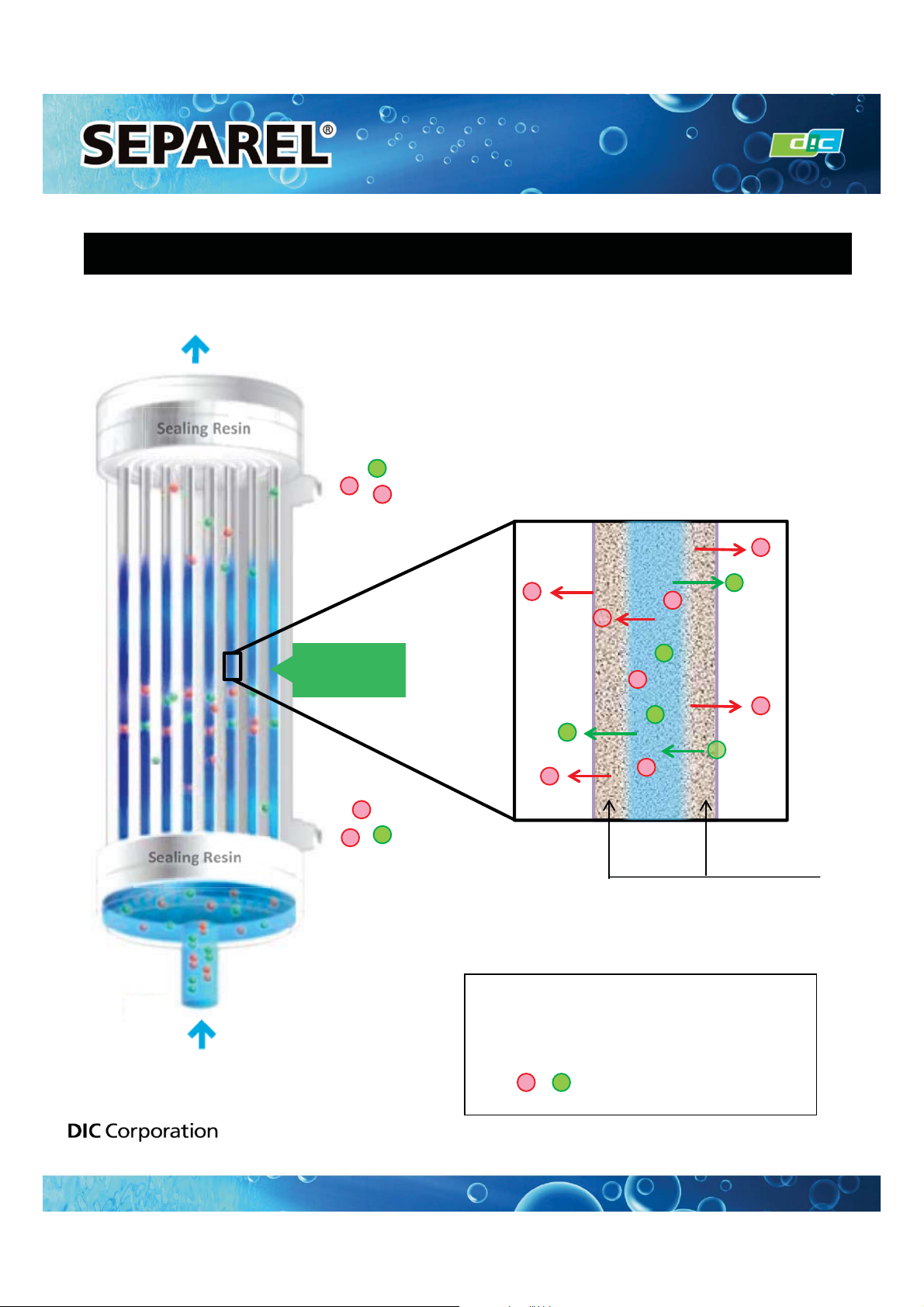
Sealing Resin
Sealing Resin
Hollow Fibers
Hollow Fiber
Membrane
: Dissolved gas
By vacuuming inside the hollow fiber,
only gas can pass through hollow fiber
membrane and is removed from liquid.
Vacuum
Liquid
Image of Hollow Fiber Cross-section
INSTRUCTION MANUAL
REFRENCE DATA 1: Basic Principles of Degassing
Application Materials Product Division

15
Perfect Vacuum
Atmosphere Pressure
Pressurization Vacuuming
Absolute
Pressure
1 atm
=101.3 kPa(abs)
= 1013 mbar(abs)
= 760 Torr
Gauge
Pressure
-1atm
= - 101.3 kPa
= - 1013 mbar
= - 760 Torr
0
0
0.65 atm
= 65.8 kPa(abs)
= 658 mbar(abs)
= 494 Torr
0.35 atm
= 35.5 kPa(abs)
= 355 mbar(abs)
= 266 Torr
- 0.35 atm
= - 35.5 kPa
= - 355 mbar
= - 266 Torr
- 0.65 atm
= - 65.8 kPa
= - 658 mbar
= - 494 Torr
15
≟
Absolute Pressure
≡
For vacuuming conditions, every value should be 0 or plus. It cannot be minus.
≟
Gauge Pressure
≡
For vacuuming conditions, every value should be 0 or minus. It cannot be plus.
≋Reference≝Absolute pressure ≐Gauge pressure ≠1atm)
The value for maximum pressure resistance is indicated by gauge pressure.
⅐Note that the vacuum pressure degree in our data sheet is mainly indicated
by absolute pressure, not by gauge pressure.
REFRENCE DATA 2: Vacuum Pressure Degree
INSTRUCTION MANUAL
Application Materials Product Division

REFRENCE DATA 3: Setting Value of Vacuum Pressure Degree
16
Temperature (
Υ
)kPa(abs) Torr mbar
15 1.7 12.8 17
20 2.3 17.3 23
25 3.2 24 32
30 4.2 31.5 42
16
INSTRUCTION MANUAL
1. For Water or Aqueous Liquid
Recommended Degree of Vacuum≝5kPa(abs) ⊡10kPa(abs)
= 50mbar(abs) ⊡100mbar(abs)
The above pressure is the recommended value when using the module at 15-30Υ.
When using the module at temperatures lower than 15Υor higher than 30Υ,
please contact DIC for more details.
The above vacuuming pressure is not suitable for every application. Depending on
applications, composition, and target degassing performance, the most suitable
vacuuming value may be different from the above value.
≟Reference≝Saturated Water Vapor Pressure≡
2. For Non-Aqueous Liquid.
Recommended Vacuuming Degree: We recommend setting weaker degrees (higher in
value) than the recommended saturated vapor pressure of the liquid.
Ex≝In cases where saturated vapor pressure is 8kPa(abs), we recommend a weaker vacuum
degree than 10kPa(abs).
As the vacuum pressure degree approaches a perfect vacuum, degassing
performance is improved. However, if the vacuum pressure degree is too strong
yet close to perfect pressure, liquid may evaporate and penetrate through the
membrane. As a result, the composition of liquids may change. Therefore, DIC
recommends following the exact vacuum pressure degree.
Application Materials Product Division

17
17
ᵮᶐᶍᶂᶓᶁᶒ ᵫᵿᶖᶇᶋᶓᶋ ᵮᶐᶃᶑᶑᶓᶐᶃᴾᵰᶃᶑᶇᶑᶒᵿᶌᶁᶃ
ᵮᵤᵋᵎᵎᵏᵢᴾᶑᶃᶐᶇᶃᶑ •†‥‒‿⁂⁓‒‚ ‒‥‒⁔⁓‛
ᵮᵤᵋᵎᵎᵒᵢ ᶑᶃᶐᶇᶃᶑ •†‥‒‿⁂⁓‒‚ ‒‥‒⁔⁓‛
ᵮᵤᵋᵎᵏᵓ ᶑᶃᶐᶇᶃᶑ •†‥‒‿⁂⁓‒‚ ‒‥‒⁔⁓‛
ᵮᵤᵋᵎᵑᵎᴾᴾᴾᶑᶃᶐᶇᶃᶑ •†‥‒‿⁂⁓‒‚ ‒‥‒⁔⁓‛
ᵮᶐᶍᶂᶓᶁᶒ ᵤᶊᶍᶕ ᵟᶐᶃᵿ
ᵮᵤᵋᵎᵎᵏᵢᴾᶑᶃᶐᶇᶃᶑ •†‒•‒‾‡⁚
ᵮᵤᵋᵎᵎᵒᵢ ᶑᶃᶐᶇᶃᶑ ‥‒‣•‒‾‡⁚
ᵮᵤᵋᵎᵏᵓ ᶑᶃᶐᶇᶃᶑ ‧•‒‧••‒‾‡⁚
ᵮᵤᵋᵎᵑᵎᴾᴾᴾᶑᶃᶐᶇᶃᶑ ‣••‒‣„•••‒‾‡⁚
Make sure that the liquid feeding pressure at the inlet port is lower than the maximum pressure value described in
the specification sheet.
If the feeding pressure exceeds the maximum value, even momentarily, the hollow fiber may be damaged and ink
may leak into the vacuum line.
The warranty will not apply in cases where liquid feeding pressure exceeds the maximum pressure value
specified in the specification sheet,
INSTRUCTION MANUAL
Even if liquid feeding pressure is lower than the specified maximum pressure, an increased flow rate will cause
lesser degassing performance. On the other hand, if the flow rate is too low, degassing cannot be efficient.
Therefore, DIC supplies recommended flow ranges in the table below.
The recommended flow range below was calculated when using water. In the case of high viscosity liquid, a
suitable flow range will be more narrow.
REFRENCE DATA 4: Setting Value of Vacuum Pressure Degree
Application Materials Product Division

18
18
ᵮᶐᶍᶂᶓᶁᶒ ᵧᶌᶌᶃᶐ ᵴᶍᶊᶓᶋᶃᴾᵿᶒᴾᵪᶇᶏᶓᶇᶂᴾᵮᶍᶐᶒ
ᵮᵤᵋᵎᵎᵏᵢᴾᶑᶃᶐᶇᶃᶑ ″†‒‒‥• ‾
ᵮᵤᵋᵎᵎᵒᵢ ᶑᶃᶐᶇᶃᶑ ″†‒‣• ‾
ᵮᵤᵋᵎᵏᵓ ᶑᶃᶐᶇᶃᶑ ″†‒••‒ ‾
ᵮᵤᵋᵎᵑᵎᴾᴾᴾᶑᶃᶐᶇᶃᶑ ″†‒․••• ‾
INSTRUCTION MANUAL
REFRENCE DATA 5: Inner Volume
The above values are for reference and are not guaranteed values.
Actual volume may differ by connection type.
Application Materials Product Division

19
19
Problems Probable Causes How to Solve the Problem
Dissolved gas
concentration
is higher than
specified or
performance
deteriorates
after use
䞉Stains on the
degasification module.
䞉Cleansing of degasification module (refer to the Cleansing
Guidelines).
䞉The dust cover during
transportation is not removed.
䞉Confirm that the dust plug for transportation is removed from
the vacuum port.
䞉Occurrence of an air leak in
vacuum line.
䞉Re-tighten the flange connection on the gas side.
䞉Perform a leak test by adding pressure to the gas line:
- Liquid soap testing: Find bubbles
- Pressure testing: Observe pressure decrease after pressing
- Use an electronic leak detection system
䞉Contact the DIC Corporation.
䞉Vacuum degree is low
due to a vacuum-related air
leak.
䞉Confirm that a properly-sized vacuum system for the system is
selected and that a properly-sized vacuum manifold is selected to
handle the vapor load of the system. This will
create a proper system.
䞉Check for air leaks in the system. If the dissolved gas
concentration at the exit is within the limit values of the sizing
estimate, it is very likely that the leak is happening in the vacuum
line behind the degasification module. If water is found inside the
degasification module, try to maintain a vacuum state by removing
liquid using a vacuum pump. Find the area where liquid has
collected inside the vacuum pipe.
- Confirm that the vacuum line is connected to the vacuum
system by slanting it downward from the degasification module.
If it is not, redo the piping.
- Remove the vacuum pumping line from the degasification
module. If the water leak exceeds 20ml/min, contact DIC.
- Since flocculated water tends to collect easily,
have the vacuum manifold insulated.
䞉Install a vacuum pump that has larger capacity.
䞉Contact the DIC Corporation.
INSTRUCTION MANUAL
REFRENCE DATA 6: Troubleshooting
Application Materials Product Division

20
20
Problems Probable Cause How to Solve the Problem
Dissolved gas
concentration is
higher than
specified or
performance
deteriorates after
use
䞉Condensation inside the
degasification module or vacuum line.
䞉If the degasification module is still wet at shutdown, there
is a possibility that flocculation of water is happening on the
shell side (inside the hollow fiber).
- Purge the flocculated water inside the hollow fiber with gas
to remove it.
- Send the sweep gas until no water droplets are found at the
gas exit port.
- If the above treatments are not successful, contact the DIC
Corporation.
䞉Find the water-blocked area inside the vacuum pipe.
- If the vacuum line is connected to the vacuum system and
slanting downward from the degasification module, redo the
plumbing in accordance with the specifications in this
manual.
- Because flocculated water tends to collect easily,
have the vacuum manifold insulated.
- Remove the vacuum pumping line from the degasification
module. If a large amount of water leaking is observed
without sweep gas, please contact DIC.
䞉Liquid temperature is lower than the
designated temperature.
䞉Raise the temperature.
䞉Liquid volume is higher than the
design specifications.
䞉Lower the liquid volume.
䞉Liquid flow volumes among the
systems of the degasification modules
are not equal.
䞉Check the flow volume of the systems.
䞉Adjust the valves to make the flow volume equal.
INSTRUCTION MANUAL
REFRENCE DATA 6: Troubleshooting
Application Materials Product Division
This manual suits for next models
4
Table of contents


