Arsin AR100 User manual

Air Compressor Controller Unit
AR100 USER’S MANUAL
All rights reserved. The content may be changed without prior notice. Rev. 00
Page 1 of 10
CAUTION
For proper and safe use of the compressor, please follow all instructions and
safety precautions as identified in this manual, along with general safety
regulations and practices. Before installing and starting the compressor,
read and understand this manual.

Air Compressor Controller Unit
AR100 USER’S MANUAL
All rights reserved. The content may be changed without prior notice. Rev. 00
Page 2 of 10
Table of Contents
1.General Safety Warnings..........................................................................................3
2.Technical specifications............................................................................................5
3.Operation..................................................................................................................6
3.1.Compressor start-up...................................................................................................... 6
3.2.Display panel ................................................................................................................. 7
3.3.Panel Buttons................................................................................................................. 8
4.Controller installation ................................................................................................8
4.1.Wiring and I/O Connections........................................................................................... 8
4.2.Fault Signals.................................................................................................................. 9
4.3.Controller Menu ........................................................................................................... 10
List of Tables
Table 1: Input/Output Terminals................................................................................................... 9
Table 2 : Setting Menu Items ..................................................................................................... 10
List of Figures
Figure 1: Compressor Start/Stop Sequences............................................................................... 7
Figure 2: Controller Display Panel................................................................................................ 7
Figure 3: Controller Back Cover................................................................................................... 8
Figure 4: Compressor Error Messages........................................................................................ 9

Air Compressor Controller Unit
AR100 USER’S MANUAL
All rights reserved. The content may be changed without prior notice. Rev. 00
Page 3 of 10
1. General Safety Warnings
Note! The instructions provided in this manual have been written to assist the operator
throughout the use and maintenance of the compressor and its controller (AR1710).
Important instructions for the safe use of the compressor warning: the inappropriate use
and poor maintenance of the compressor and its controller may cause physical injury to
the user. You are recommended to carefully follow the instructions provided hereafter to
avoid such risks.
Do not touch moving parts. Never put your hands, fingers or other parts of the
body near moving parts of the compressor.
Never use the compressor without the safety guards fitted. Never use the
compressor without all the safety guards fitted perfectly in their correct place (i.e.
panelling, belt guard, safety valve). If these parts are to be removed for
maintenance or servicing purposes, ensure that they are put back in their original
place perfectly before using the compressor again.
Always wear safety goggles. Always wear goggles or equivalent eye protection
means. Never direct compressed air towards any part of your body or that of
others.
Protect yourself against electric shocks. Avoid accidentally touching the metal
parts of the compressor with your body, such as pipes, the tank or metal parts
connected to earth. Never use the compressor where there is water or in damp
rooms.
Disconnect the compressor. Disconnect the compressor from the electric power
supply and completely discharge the pressure from the tank before carrying out
any service, inspection, maintenance, cleaning, replacing or inspection jobs of
each part.
Never move the compressor while it is connected to the electrical power supply
or when the tank is pressurized. Ensure that the main switch is turned off before
connecting the compressor to the electrical power supply.
Store the compressor and its controller appropriately. When the compressor is
not in use, it must be stored in a dry room away from atmospheric agents.
Keep the work area clean and remove any tools that are not required. Keep the
work area sufficiently ventilated. Never use the compressor in the presence of
flammable liquids or gas. The compressor may produce sparks while running. Do
not use the compressor where there may be paints, gasoline, chemical
compounds, glues and any other flammable or explosive material.
Do not wear unsuitable clothing, ties or jewellery as these may get caught up in
moving parts. Wear caps to cover your hair if necessary.

Air Compressor Controller Unit
AR100 USER’S MANUAL
All rights reserved. The content may be changed without prior notice. Rev. 00
Page 4 of 10
Do not disconnect the power supply plug by pulling on the cable. Keep the cable
away from heat, oil and sharp edges. Do not stand on the electrical cable or
squash it under heavy weights.
Follow the maintenance instructions. Inspect the power supply cable on a
periodic basis and if damaged it must be repaired or replaced by an authorised
service centre. Visually check the outside appearance of the compressor,
ensuring that there are no visual anomalies. Contact your nearest service centre
if necessary.
Pay attention to everything you do. Use your common sense.
Do not use the compressor if you are tired. The compressor must never be used
if you are under the effect of alcohol, drugs or medicines, which could make you
tired.
Use the compressor and its controller exclusively for the applications specified in
this instruction manual.
Operate the compressor in compliance with the instructions provided in this
manual. Do not allow children to use the compressor or those who are not
familiar with it.
Ensure that each screw, bolt and guard is firmly secured in place.
Keep the in-take grids clean. Keep the motor ventilation grids clean. Regularly
clean these grids if the work area is particularly dirty.
Operate the compressor at the rated voltage. Operate the compressor at the
voltage specified on the electric data plate. You could damage or burn-out the
motor and other electric components if the compressor is operated at a higher or
lower voltage than its rated voltage.
Never use the compressor if it is faulty. If the compressor is noisy or vibrates
excessively when running or it seems to be faulty, stop it immediately and check
its efficiency or contact your nearest authorised service centre.
Do not clean plastic parts using solvents. Solvents such as gasoline, thinners,
gas oil or other compounds that contain hydrocarbons may damage the plastic
parts. Clean them with a soft cloth and soapy water or other suitable liquids.
Turn the compressor off when it is not in use. When the compressor is not in use
turn the main on/off switch off.
Keep this instruction manual carefully and give them to personnel wishing to use
the compressor!
We reserve the right to make modifications where necessary without notice.

Air Compressor Controller Unit
AR100 USER’S MANUAL
All rights reserved. The content may be changed without prior notice. Rev. 00
Page 5 of 10
2. Technical specifications
Input Power AC 220V 50/60Hz
Power Consumption Max. 4 VA
CPU AT mega 8, 16MHz
Display 2 x 7-segments Numerical Display
Digital Inputs:
Input Type Opto-Isolation
Number of Inputs 7 Points (1 Common)
Signal Power 12VDC
Digital Outputs:
Output Type Relay Contact
Number of Output 5 Points (1 Common)
Relay Contact Type 250 VAC, 7 Ampere
Analog Inputs:
Temp. Sensor PTC (Pt-1000)
Internal Sensor Power 12V
Deviation Correction Software
Installation Conditions:
Installation Place Indoor
Operating Temperature -10 ~ +60°C
Storage Temperature -30 ~ +80°C
Operating Humidity 5 ~ 95% (Non- condensable)
Dimensions 235 x 86 x 78 mm (Width x Height x Depth)

Air Compressor Controller Unit
AR100 USER’S MANUAL
All rights reserved. The content may be changed without prior notice. Rev. 00
Page 6 of 10
3. Operation
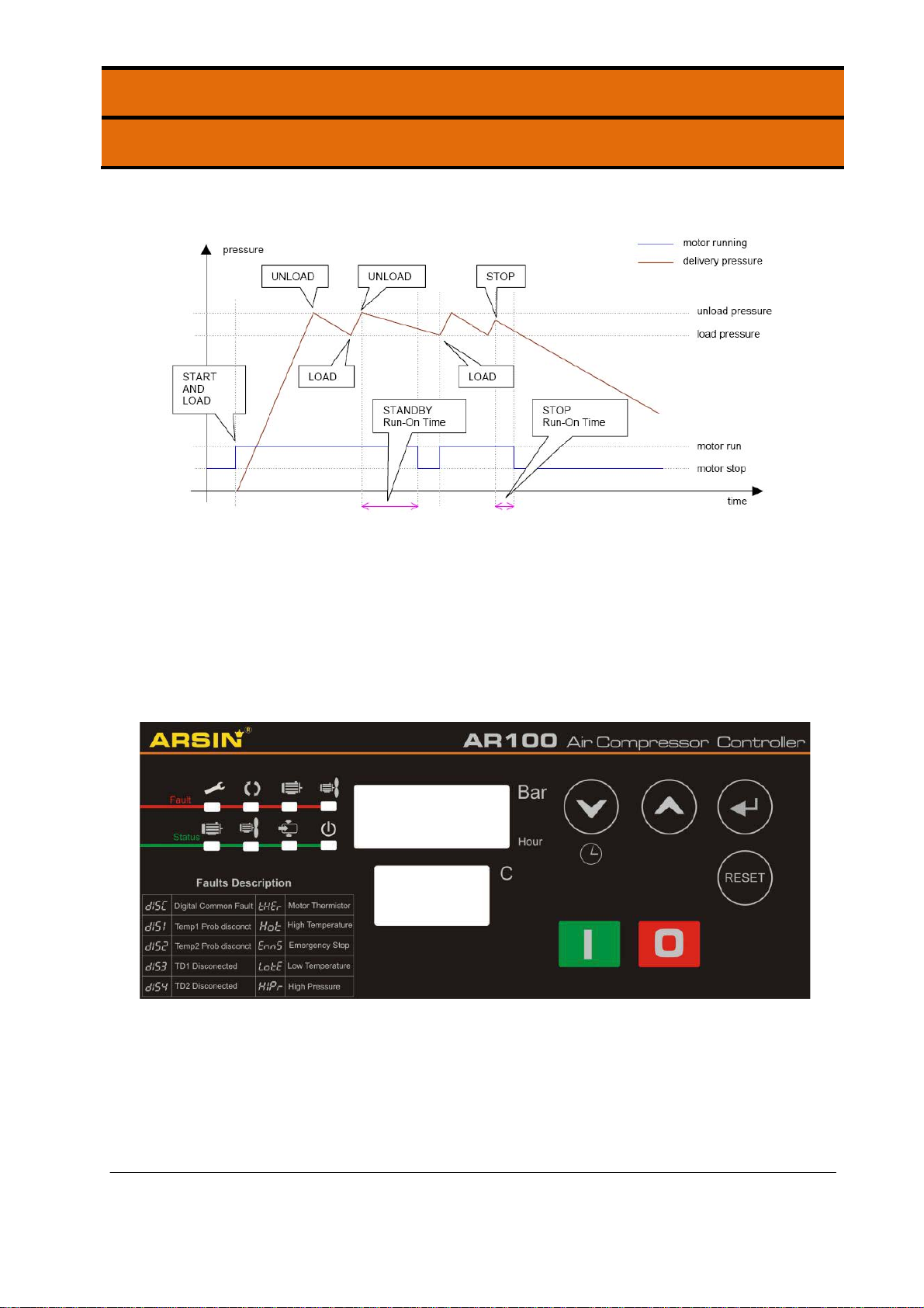
3.1. Compressor start-up
In normal operation, the detected delivery pressure controls regulation of the
compressor once the compressor has been started by pushing the start button, or by a
remote start command if enabled. The controller will perform safety checks and start the
compressor if no inhibiting conditions are detected.
If a start inhibiting condition exists the compressor will not enter the started condition
and a start inhibit message is displayed. If a run inhibiting condition exists the
compressor will enter the started condition but a main motor start is inhibited; the
compressor will remain in the standby condition and a run inhibit message is displayed.
If a load request is present, in accordance with internal pressure settings or by remote
command, the main motor is started in a star/delta sequence. When running in delta
configuration, after the star/delta time (adjustable) has expired, the load delay time
(adjustable) prevents loading for a period to allow motor speed to stabilize. The load
delay time can be set to one second if required. When the load delay time has expired
the load valve output is energized and the compressor will load. If the unload pressure
setting is reached, or a remote unload command is received, the load valve output is de-
energized and the compressor will run offload for the standby run on time (adjustable)
before the main motor stops and the compressor enters Standby mode. The compressor
will load again if pressure falls below the load setting before the standby run on time
expires. If in Standby mode, a motor start sequence followed by the load delay time is
executed before loading.
In the event of a motor stop, initiated by a stop command or when entering standby
mode, a blow down timer (adjustable) is started. If a start request is made during the
blow down time the compressor will enter standby mode until the blow down time
expires. If already in standby mode and a load request is present, the compressor will
remain in standby mode until the blow down time has expired. For units with internal
pressure detection enabled, a minimum internal re-start pressure can also be set to
prevent a motor start sequence before internal pressure is vented. In the event internal
pressure fails to fall below the set minimum re-start pressure within two minutes after the
set blow down time has expired, a blow down fault is generated and the compressor will
shutdown. After an unload event a re-load timer (adjustable) is initiated that will prevent
reloading, this time can be adjusted to a minimum of one second if required. Normal
automated operation is ended by pushing the stop button, a remote stop command or in
the event of a shutdown fault.
When stopped manually, or by a remote command, the load value is de-energized and
the main motor allowed to run-on for the stop run on time (adjustable). This time can be
adjusted to a minimum of one second if required. Safety checks are made continuously,
if there is a condition detected that presents a hazardous or damaging situation an
immediate stop is performed and the reason displayed as a shutdown error message. If
a warning condition is detected an Alarm message is displayed and normal operation
continues.

Air Compressor Controller Unit
AR100 USER’S MANUAL
All rights reserved. The content may be changed without prior notice. Rev. 00
Page 7 of 10
Figure 1: Compressor Start/Stop Sequences
3.2. Display panel
The following information is shown on controller display panel.
Figure 2: Controller Display Panel

Air Compressor Controller Unit
AR100 USER’S MANUAL
All rights reserved. The content may be changed without prior notice. Rev. 00
Page 8 of 10
3.3. Panel Buttons
Start The equipment starts when pushing start button.
Stop The equipment stops when pushing stop button.
Reset
Reset when trip
[ Press and hold Reset button in order to enter to
Manufacturer Setting Menu ]
Enter Enter to programming Menu / Enter to next Menu Level
Up Increase Selected Value
Down Decrease Selected Value
4. Controller installation
4.1. Wiring and I/O Connections
The following figure shows controller back-cover. The I/O connections are categorized
and numerated as shown in below table.
Figure 3: Controller Back Cover

Air Compressor Controller Unit
AR100 USER’S MANUAL
All rights reserved. The content may be changed without prior notice. Rev. 00
Page 9 of 10
Table 1: Input/Output Terminals
Cat.PinNameFunctionActivestate/Range
Power
Supply1&2MPMainPowerSupply220VAC
Cat.PinNameFunctionActivestate/Range
Power
Outputs
19ValveSolenoidValveOutputOutput(NO)
20NormNormalContactorOutputOutput(NO)
21YStarContactorOutputOutput(NO)
22Δ DeltaContactorOutputOutput(NO)
23FanFanMotorOutputOutput(NO)
24ComPowerCommonTerminal‐
4.2. Fault Signals
The fault signals showing compressor malfunction are shown on upper display unit and
are described on the panel as shown below.
Figure 4: Compressor Error Messages
Analog
Inputs
5&6TempTemperatureSensor(Pt1000)‐50~+150oC
9&10TD#1 4~20mA
Digital
Inputs
11TSWTemperatureSwitchSignalAlarm(close)
12PSWPressureSwitchSignalAlarm(close)
16EMSEmergencyStopSignalAlarm(close)
12PhasePhaseFaultSignalAlarm(close)
14FanFanBimetalFaultSignalAlarm(close)
13MotorMotorBimetalFaultSignalAlarm(close)
17RmtRemoteInputSignalRemote(close)
18ComInputCommonTerminal

Air Compressor Controller Unit
AR100 USER’S MANUAL
All rights reserved. The content may be changed without prior notice. Rev. 00
Page 10 of 10
4.3. Controller Menu
Table 2 : Setting Menu Items
Menu Item Display Set-point Range
1.1. Maximum Discharge Air
Pressure 7 ~ 10 barg
1.2. Range of Pressure
Transmitter Measurement variable
1.3. Operation Mode 0: Pressure Transmitter
1: Pressure Switch
2: Remote set-point
1.4. Maximum Temperature +90 ~ +120 oC
1.5. Start Delay Time 01 ~ 60 Sec.
1.6. Star-Delta Delay Time 02 ~ 20 Sec.
1.7. Load Delay Time 01 ~ 60 Sec.
1.8. Stop Delay Time 01 ~ 60 Sec.
1.9. Standby Time 01 ~ 60 Min.
1.10. Fan Turn-on Temperature +55 ~ +80 oC
1.11. Fan Turn-off Temperature +20 ~ +50 oC
1.12. Minimum Start Temperature -50 ~ +20 oC
1.13. Auto Restart Yes / No
1.14. Temperature Offset -25 ~ +25 oC
1.15. Change Password 4 digit
1.16. Service Time Service Hours
1.17. Reset Service 0: Alarm only
1: Shutdown
1.18. Alarm/Shutdown Mode 0 : Alarm
1: Shutdown
Table of contents
Other Arsin Control Unit manuals