Dickinson Caribbean Specification sheet

Caribbean/Mediterannean
2 Burner Stove 3 Burner Stove
Propane Galley Range
Operating and Installation Manual
This instruction manual contains important information
necessary for the assembly, installation and safe operation
of this stove
Form#7.2-247 Issue#1
Mar 15th 2016
Serial #
____________


3
Table of Contents
4................................................................................................General Warnings
6...............................................................LP Gas Cylinder Specs and Installation
7....................................................................................About our Dickinson Stove
8..............................................................................................Stove Specifications
9...........................................................................................................Accessories
10................................................................................Standard Cutout Installation
11...................................................................................Gimbal Cutout Installation
12..............................................................................Built In Kit Cutout Installation
13...........................................................................................................Installation
14......................................................................................................Fuel Systems
15............................................................................................................Operation
.
17.......................................................................................................Maintenance
19.............................................................................Caribbean Exploded Diagram
20.....................................................................Mediterannean Exploded Diagram
21.................................................................................Caribbean Wiring Diagram
22...........................................................................Mediterranean Wiring Diagram
23..................................................................................................Troubleshooting
24.............................................................................................Replacement Parts
25...................................................................................................Warranty Policy
26....................................................................................................Warranty Form

4
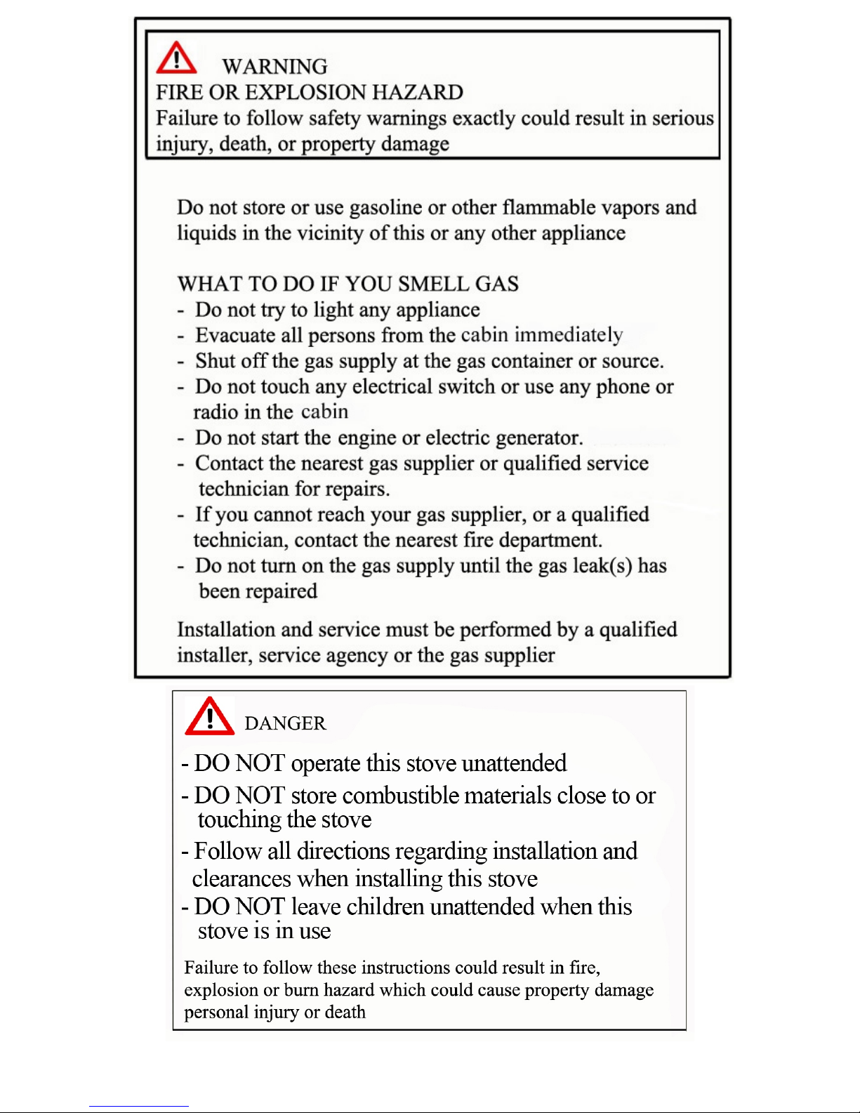
ŸLeak test all connections before 1st use
ŸLeak test all connections after each tank refill
ŸNever check for leaks using an open flame. Use soapy water on the
connections and look for bubbles being produced.
ŸAlways check the stove, tank and hose connections prior to each use
ŸThis stove is configured for propane. Do not use natural gas.
ŸNever use charcoal, lava rocks or any other source of solid fuel in this
stove
ŸEnsure that flames are coming out the entire circumference of the
burners or length of the broiler. Occasionally insects can enter the
unit when not in use and create blockages which can lead to fires.
ŸNever use or store gasoline or any other flammable products in or
near your heater
ŸKeep children and pets away from a hot appliance. DO NOT allow
children to operate
ŸDo not leave this stove unattended when in use
ŸKeep any electrical cords away from the stove when it is in use
ŸDO NOT operate under the influence of alcohol or drugs
ŸDo not use any other regulator than ones supplied or recommended
by Dickinson Marine
ŸThis stove becomes hot when in use. To avoid burns
- DO NOT attempt to move
- Wear protective equipment
- DO NOT touch any hot surface
- Do not wear loose clothing while operating
ŸThis stove is not intended for commercial use
ŸAdhere to all clearances listed in this manual
ŸFor recreational vehicle installation, the Standard for Recreational
Vehicles, ANSI A119.2, or the Standard for Gas Equipped
Recreational Vehicles and Mobile Housing CSA Z240.4

5
ŸA manufactured home (USA only) or mobile home OEM installation
must confirm with the Manufactured Home Construction and Safety
Standard, Title 24 CFR, Part 3280,or, when such standard is not
applicable, the Standards for Manufactured Home Installations, ANSI
A225.1/NFPA 501A, or Standard for Gas Equipped Recreational
Vehicles and Mobile Housing, CSA Z240.4
ŸToddlers, young children, and others may be susceptible to accidental
contact burns. A physical barrier is recommended if there are at risk
individuals in the house. To restrict access to a fireplace or stove,
install an adjustable safety gate to keep toddlers, young children and
other at risk individuals out of the room and away from hot surfaces
ŸClothing or other flammable material should not be placed on or near
the appliance
ŸAny safety screen, guard or barrier removed for servicing the
appliance must be replaced prior to usage
ŸLabel all wires prior to disconnecting when servicing controls. Wiring
errors can cause improper and dangerous operation after service.
Verify proper operation after service prior to firing.
ŸInstallation and repair should be done by a qualified service person.
The appliance should be inspected before use and at least annually
by a professional service person. More frequent cleaning might be
required due to excessive lint from carpeting, bedding material etc. It
is imperative that control compartments, burners and circulating air
passageways of the appliance be kept clean.
*** FAILURE TO ADHERE TO THE SAFETY WARNINGS LISTED IN
THIS MANUAL COULD RESULT IN DAMAGE TO PROPERTY OR
SEVERE PERSONAL INJURY***

6
LP GAS CYLINDER SPECS AND INSTALLATION
ŸThe stove and its individual shutoff valve must be disconnected from
the gas supply piping system during any pressure testing of that
system at test pressures in excess of 1/2 PSI (3.5kPa)
ŸThe appliance must be isolated from the gas supply piping system by
closing it’s individual manual shut-off valve during any pressure testing
of the gas supply piping system in equal or less than 1/2 PSI (3.5kPa)
ŸThe LP gas supply cylinder to be used MUST be constructed and
marked in accordance with the specifications for LP gas cylinders,
U.S. Department of Transportation (DOT) or the standard for cylinders,
spheres and tubes for the Transportation of Dangerous Goods,
CAN/CSA-B339
ŸThe propane supply cylinder system must be installed with proper
vapor withdrawal capabilities
ŸA pressure regulator must be used in the operation of this unit which
will emit the propane at a pressure of 11”W/C
ŸAny replacement regulators must be of those specified by the
appliance manufacturer

7
About our Propane Galley Stoves
One of our newer appliances, our Dickinson propane galley ranges are clean burning
appliances designed for use in marine environment but are adaptable to many applications.
With a large range of setting they are ideal for all cooking situations and are great to have
in any galley. Made out of attractive stainless steel our stoves are durable and beautiful.
The stainless design is resistant to corrosion and will keep its shine for many years. The
burners have porcelain capping for a nice glossy black look which looks great with grained
finish of the stove. Paired with the laser cut lettering, the propane galley ranges are a must
have.
Each Dickinson range comes standard with one set of polished pot holders, a
stainless cooking rack, a finished wood cutting board as well as a stainless steel potholder
rail. The stoves are designed to sit in a standard cut out and can be mounted three
different ways. Straight into a cut out, built in with stainless steel accent pieces or gimbal
mounted for use in light chop. Any way it is mounted, your propane range will offer
dependable service for years to come. When not in use, place the cutting board into the
stove top and you have increased counter space.
These stoves operate on 11” W/C pressure and require a dedicated regulator or a 2
stage regulator for a multiple appliance set up. All burners are equipped with thermocouple
controlled flame out protection as well as automatic spark ignition for ease of use and the
oven is thermostatically controlled and maintains a nice even temperature. All around the
stoves are easy to use and reliable.

8
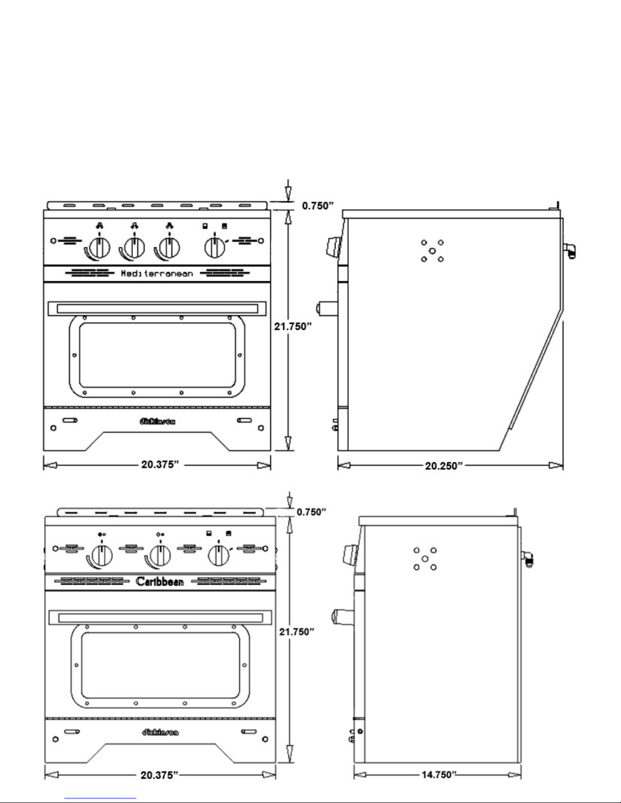
Galley Specifications
Galley Dimensions
Height
Width
Depth
Weight
Burner BTU Range
Small Top
Large Top
Broiler
Oven
Oven Temperature Range
Oven Size (Usable)
Height
Width
Depth
Gimbal Point
Height
From Front
From Rear
Mediterranean
21”
20.5”
20”
80lbs
2300 - 7000 (x2)
4300 - 11000
4500
7000
9”
16”
12.5”
18”
7.5”
11.5”
Caribbean
21”
20.5”
14.75”
70lbs
2300 - 7000
4300 - 11000
4500
7000
9”
16”
12.5”
18”
7.5”
7”
Automatic Spark Ignition - Each burner is equipped with an automatic spark ignitor which is engaged as
soon as the burner knob is pressed down to allow gas. This does not allow for any build up of propane gas
that could create a potentially dangerous situation.
Thermocouple Controlled Flame Out Prevention - Each burner is equipped with flame out protection. In
the event that a burner is accidentally blown out, the thermocouple will sense the lack of heat and disengage
the valve and prevent any gas build up.
Thermostatically Controlled Oven - The oven in our propane galley range is controlled thermostatically
with a probe located inside the oven that regulates the cooking temperature. With a cooking range from 250
to 450 degrees your oven is capable of cooking a variety of items
Triple Burner - The large burner is a patented triple burner design which allows the Dickinson propane
galley range to boast the most powerful marine stove burner (11000 BTUs). The Burner can be turned
down to a third of the BTU’s for slower cooking.
Product Features

9
Included Accessories
Cutting Board - The cutting board is a nice addition
to the propane galley. It sits flush in the sink cutout
creating more counter space and has cut outs in the
back eliminating the need to remove the pot holder
rail.
Mediterranean - 26-011
Caribbean - 26-010
Cooking Grate - The cooking grate is made of
beautifully polished stainless steel and sits tight on
four anti-rattle pins. It is equipped with locking slides
on the front and back for your pot holder rail as well
as 4 adjustable leveling points for your cutting board.
Mediterranean - 26-031
Caribbean - 26-030
Pot Holders - Your propane galley comes with a set of
pot holders. They can be adjusted to fit any sized pot
as they are placed individually on the pot holder rail
and once in place will not move.
Mediterranean - 20-020A
Caribbean - 20-020
Pot Holder Rail - The pot holder rail serves the dual
purpose of holding the pot holders and offering a small
raised barrier against sliding pots in small chop.
26-021
Tie Down Bar - This is used to secure the stove
underneath at the back where it is inaccessible

10
Standard Cutout
If installing your Mediterranean or Caribbean propane stove into a cutout, the cutout needs to be a
minimum of 20.5” wide for either stove and 22” deep for the Mediterranean or 16.5” for the Caribbean. A
cutout is not necessary as the stove can be freestanding. Once mounted the stove needs to be secured
with the tie down bar and two screws in the front below the door.
10

11
Built In Kit Cutout
The built in kit is designed to give your stove that pre-existing “built-in” look. There are three
different ways to install the kit. Please note the cutout width below that applies to your application.
1) The brackets can be mounted on the counter top so that they sit 3/8” higher then the rest of the
counter top. Cutout width for this install would be 20.5” to 22.25”.
2) The brackets can be mounted to the sides of the cabinets so that they are level with the counter top.
Cutout width for this install would be minimum 22.5” wide.
3) The brackets can be mounted to the sides of the stoves so that they are level with the stove top.
Cutout width for this install would be 20.5” to 22.25”.
Built In Kit Part #
Caribbean - 26-000
Mediterranean - 26-001

12
Gimbal Cutout
To install the stove on a gimbal you would need to locate the proper area to mount the gimbal
brackets to allow the stove to swing freely with no obstruction. To do this you would need to make a
cardboard template of the side of the stove and pierce it where the mounting bolt would screw in. Swing
the stove from this hole to visualize the arc of the stove and identify the proper gimbal mounting points.
The minimum cutout width is 22” and if your cutout is too wide you can place shims underneath the gimbal
mounting brackets to close the gap.
Be sure to adhere to the proper clearances and to allow for enough slack on the propane line to
accommodate the swinging.
Gimbal Kit Part # - 26-003
12

13
Installation
The specifics of your installation will differ depending on the method of installation. Fuel lines, securing
methods and clearances will depending on if the stove is gimbaled or installed in a cutout secured to the deck.
Standard Cut Out/Built in Cut Out
In this installation you would secure the stove to the deck using a combination of the tie down bar and
screwing down the body. To secure the stove you would first need to screw down the tie down bar in the
appropriate spot in the cut out. To do this you would need to measure the distance from where the front of the
stove will be located to the back edge of the bottom of the stove. When have this measurement you would
screw the tie down bar to the deck so that the bend in the tie down bar is level with where the back of the stove
will be. Slide the stove into the cutout and the bottom panel will slide underneath the tie down bar. This will
only prevent the stove from tipping in rough weather. To secure the stove further, once it is slide into place you
would remove the door and on either side of the stove there are holes in the bottom panel. You need to drive
screws through these holes to secure the stove. The combination of the tie down bar and the screws will hold
the Stove securely.
Clearances for all Installations
No clearance is needed on either side of the stove as well as below. 2” of clearance is required behind the
stove for the propane hookup, however the counter top can be brought right up to the back of the stove in
stationary installations as the oven vents inside the cook top where the burners are located and not out the
back. Above the stove we recommend at least 36” of clearance.

14
Fuel Supply
LPG System Installation
**In some cases the solenoid valve is installed on the high pressure side of the system (ie before the LPG
regulator). See solenoid manufacturers instruction for proper installation
1. Starting from the propane tank itself, the fuel line attachments should occupy the following positions: 1)
Pressure gauge, 2) Low pressure or two stage regulator, 3) Solenoid (optional), 4) The appliance itself
2. In gimbaled installations, the gas supply line should be a flexible fire resistant hose, UL/CGA approved
for use with propane systems with a 3/8” (10mm) forged female flare nut machine crimped on each end.
3. If your range is a standard or built in style installation, you should use either soft copper tubing or a
UL/CGA approved gas hose with a 3/8” (10mm) forged female flare nuts machine crimped on each end.
4. Because every connection is a potential leak, the fuel line should be one continuous length of hose or
tubing. DO NOT make a “T” off the fuel line between an existing appliance and the gas cylinder to feed
another appliance. You may install a “T” ONLY within the fuel tanks enclosure (propane locker)
5. Be sure not to kink the hose or piping connecting the regulator with the range by bending it too sharply
during installation - remember that the pressure (North American) on the downstream side of the regulator
is 0.433 PSI (28mBar)
6. Protect the hose against vibration and damage by securing it tightly to bulkheads and hull side with
non-corrosive ties or clamps which will not cut, abrade or pinch it.
7. Fuel lines must be protected by close fitting grommets and sealants where they pass through decks
and bulkheads and the passage must be made vapor tight. Also they should be installed so that they are
readily accessible for inspection

15
Operation
First Use
Once your stove is installed it is recommended that you use a soapy water solution to check for
leaks at the connection at the back. Cover the entire connection in the solution and turn the gas on at the
tank. DO NOT light the stove but rather observe the connection for any air bubbles. If no bubbles appear
after 2 minutes, light the stove. If you do observe bubbles, shut the gas off, tighten the connection and
allow 5 minutes for the escaped gas to dissipate and then turn the gas back on. DO NOT use the stove
until you are sure the connection at the back is sealed. Always use 2 wrenches when connection the
propane hose to the fitting.
Top Burners
Before lighting the top burners ensure that the large burner top is seated properly on its base and
that the small burner top(s) are not loose. To light the burners, press in the knob (this will engage the
electronic spark ignition) and turn counter-clockwise to the High position. The burner should light within 5
seconds. If the burner does not light, turn the knob to the off position and allow any gas to dissipate
before attempting to light again.
NOTE - The burners may take a little longer to light on initial usage as the air will need to bleed out of the
lines.
Small Burner(s) - Each small burner is a single ring burner with a maximum out put of 7000BTU and a
minimum of 2300BTU once warmed up. Once lit, flame should be coming out of the entire circumference
of the burner. If flame is missing in any area it could mean that the burners flame spreader is clogged at
that point and needs to be cleaned (see Maintenance).
Large Burner - The large burner is a triple ring burner with a maximum out put of 11000BTU and a
minimum of 3600BTU. Once lit, flame should come out of all three rings however, the middle ring and
inner ring flames will merge when on high due to the pressure of the gas so all 3 rings may not be visible.
Flame should be visible around the inner and outer edge of the outer ceramic ring as well as the
circumference of the inner ceramic cap. The flame will not be uniform around the outer ring as the
individual flames will be smaller at 4 points due to the design of the large flame spreader.
Oven
Oven Burner - The oven burner is a single ring burner located underneath the heat diffusion plate in the
oven. To light the burner, press in the knob (this will engage the electronic spark ignition) and turn
counter-clockwise. The burner may take upwards of 10 seconds to light on initial use as the air bleeds
out of the copper line and may take 10 seconds before the thermocouple engages. The Oven burner will
operate on high setting until the desired temperature is reached and then will automatically re-adjust to
maintain temperature. It is recommended to use a secondary thermometer to gauge the accuracy of the
oven temperature but a 25 degree disparity is normal. If the difference is more then you may have to
adjust the oven valve (See Troubleshooting)
Broiler Burner - The broiler burner is located in the top of the oven. To light the burner, press in the knob
(this will engage the electronic spark ignition) and turn clockwise. If you wish to use the broiler and have
just used the oven, allow 30 seconds from the time the oven has been turned off before you light the
broiler. Should the broiler not light within 5 seconds, turn the knob to the off position and allow 2 minutes
for the accumulated gas to dissipate. The broiler burner has no high-low setting and can not be used at
the same time as the oven burner. If the broiler does not light you may have to clean the orofice (See
Maintenance)
NOTE - DO NOT light the broiler or oven with the oven door closed

16
Operation
Cooking with the Top Burners
It is recommended that you use the appropriate sized pots and pans when cooking. When using a
smaller pot on the large burner ensure the flame is adjusted so that it is not burning up the sides of the
pot. This could heat the handle(s) and lead to burns. Also crowding the cooking area with a pot or pan
that is much larger can lead to uneven heat distribution.
The cooking performance is greatly affected by the type of cookware used. Proper cookware will reduce
cooking times, use less energy and produce more even cooking results. For best results use a heavy
gauge metal pan with a smooth flat bottom, straight sides and a tight fitting lid.
Cookware with uneven, warped, or grooved bottoms, do not make good contact with the heating surface
and will reduce heat conductivity and result in slower less even heating.
The pan material determines how evenly and quickly heat is conducted from the heat source to the food.
Some widely used pan materials are.
Aluminum – excellent heat conductor. Some food will cause it to darken or pit. Often used as a bottom
coating to improve the heating of other pan materials.
Copper - excellent heat conductor. Discolors easily, requires constant polishing. Often used as a bottom
coating to improve the heating of other pan materials.
Stainless Steel - slow heat conductor. Develops hot spots, and produces uneven cooking results.
Durable, attractive and easy to clean. Will distribute heat better if other materials are combined or
sandwiched together as a bottom coating.
Cast Iron – Slow heat conductor. Cooks evenly once temperature is reached. Heavy, needs seasoning
to make cleaning easier and to prevent sticking and rusting.
Glass – Slow heat conductor. Easy to clean. Some types may only be used in the oven.
Porcelain Enamel – glass-like substance fused to metal. Heating characteristics depend on base
material. Easy to clean.
Oven Cooking Considerations
Aluminum Foil – If you cover the cooking rack with aluminum foil it may prevent the hot air from naturally
circulating around the oven and could cause uneven cooking and burnt food. To catch spills, place some
foil on the drip tray below the rack. Do not place aluminum foil in the bottom of the oven and cover the
burner.
Do not crowd a rack with pans. Never place more than one cookie sheet, one cake pan or two round
pans on the rack.
Allow two inches between the pan and the oven walls

17
Maintenance
CARE AND CLEANING
WARNINGS:
1. Before cleaning the cook-top, ensure that the burners are turned off and that all components are
cool enough to safely touch.
2. After cleaning re-assemble all components before attempting to operate the cook-top.
Proper cleaning is necessary to maintain appliance performance and appearance. Wipe up spills that
occur while cooking, but wait for cooker to cool. Spills that remain on hot burner components will be very
difficult to clean, especially if allowed to burn on. Spills of certain foods, such as tomatoes, citrus juices,
vinegar, alcohol and milk are harmful if allowed to stand for any length of time.
1. Do not use any abrasive chemical cleaners on the inside, or outside of your range. Any household
liquid cleaner is recommended.
2. Use a clean cloth or sponge to apply cleaners.
3. Remove stains as quickly as possible before they become “set”.
4. Do not let food spills or burnt foods build up on any surface of your galley range.
5. You can use a household oven cleaner for the oven, but remember to follow the product
manufacturer's directions.
6. Do not use steel wool or SOS-type pads to clean any part of your stove, as these products will
embed fine steel particles in the surface of the stainless steel causing it to bleed in a marine
environment. Use bronze wool or some other nonmetallic abrasive if you must. Be aware, that
your range has a fine finish that can be scratched by some abrasive pads or cleaners.
PROLONGED LAY UP
The Dickinson Propane Stove has been designed to have a long life, with every day use. However, if you
leave your boat unattended for a long period of time, particularly in high heat and humid conditions, or long
winter conditions, the high temperature lubricant in the gas control valves may settle, resulting in difficulty in
turning the control valves and possibly seizure of the valve.
NOTE: As part of preventative maintenance, if you anticipate a prolonged lay-up period for your
stove, it is advisable that you periodically rotate your gas valves from time to time, to prevent possible
valve seizure.
In the event that your valve does seize, it will be best to remove the control panel from the range by first pulling
off the control knobs, then unscrew the acorn nuts and remove the panel. We highly recommend that you do
NOT open and service the gas valve as it is very difficult to re-assemble, ( it may damage internal parts and / or
may leak). With that being said you have a 50/50% chance of fixing or breaking the valve. Use pliers or vise
grips on the brass shaft then PUSH IN and turn counterclockwise ONLY. This will either loosen the shaft or
break it (the shaft will turn but not operate the valve).
NOTE: If you don't have experience with gas and would like to fix the valve and not take the chance of
breaking it call or better yet email tech support for guidance.
NOTE: Do a soap test on the valve after assembly to ensure there are no leaks.

18
CLEANING ORIFICE
The orifices of the burners are accessed by removing the 4 screws on the inside walls of the cooking area and
then lift the top off the stove. The large burner cap and body is simply lifted off the burner base support. This
reveals the small hole which is the gas inlet orifice. The small burner cap is unscrewed counterclockwise.
Remove the two small screws on top of the burner base and then lift off the assembly. It is advisable to
unscrew and remove the orifice for cleaning. Cleaning the orifice in place may result in a repeat blockage
soon after re-using the cook-top, however turning the orifice drill clockwise, the twisted flutes of the drill may
remove the debris upwards and out (works 70% of the time). When putting parts back on, make sure the
burner tops are put on before the stove top is reinstalled.
NOTE: When putting the small burner back on, make sure to screw in the screws evenly. Start one
screw off, then start the other, then adjust each one incrementally. If you don't, the burner will go in
crooked, and you will risk damaging it.
CLEANING THE OVEN HEAT-DISPERSER
1. Open the oven
2. Then lift up plate, and pull towards you.
3. Now you can clean the heat-disperser, by following the same care and
cleaning instructions listed above.
Maintenance

19
CARIBBEAN

20
MEDITERRANEAN
Other manuals for Caribbean
1
This manual suits for next models
1
Table of contents
Other Dickinson Range manuals
Popular Range manuals by other brands

SERV-WARE
SERV-WARE SGR-6B-C Service, installation and care manual

GE
GE JB450RFSS Dimensions and installation information

Candy
Candy TRIO 9501/1X Instructions for use and installation

Aroma
Aroma AHP-303 INSTRUCTION MANUAL RECIPE BOOK

Smeg
Smeg C9GMXA Instructions for installation and use

Techogas
Techogas Superiore RN362GPSS installation manual