Digi-Sense 20250-60 User manual
THE STANDARD IN PRECISION MEASUREMENT
User Manual
Insulation Tester
Model 20250-60
1065DGMAN_20250-60 DS Insulation tester manual.indd 1
8/7/2017 2:09:49 PM

2
Introduction
The Digi-Sense Insulation Tester (Model 20250-60) is
versatile and easy to use. The instrument is a must-have
on your electrical tool belt. It safely measures insulation
resistance of electrical devices such as cables or motor
coils up to 4000 MΩ, as well as providing a means of
measuring AC/DC voltages and circuit continuity. Careful
use of this meter will provide years of reliable service.
Safety Precautions
•Read the following safety information carefully before
attempting to operate or service the meter.
•To avoid damages to the instrument do not apply the
signals which exceed the maximum limits shown in the
technical specifications tables.
•Do not use the meter or test leads if they look damaged.
Use extreme caution when working around bare
conductors or bus bars.
•Accidental contact with the conductor could result in
electric shock.
•Use the meter only as specified in this manual; otherwise,
the protection provided by the meter may be impaired.
•Read the operating instructions before use and follow
all safety Information.
•Caution when working with voltages above 60 VDC or
30 VAC RMS. Such voltages pose a shock hazard.
•Before taking resistance measurements or testing
acoustic continuity, disconnect circuit from main power
supply and all loads from the circuit.
1065DGMAN_20250-60 DS Insulation tester manual.indd 2
8/7/2017 2:09:49 PM
3
Safety Symbols
Caution refer to this manual before using the
meter.
Dangerous voltages.
Meter is protected throughout by double insulation
or reinforced insulation.
CE Compliance with EN-61010-1
Note: When servicing, use only specified replacement
parts.
Unpacking
Check individual parts against the list of items below. If
anything is missing or damaged, please contact your
instrument supplier immediately.
1. Instrument
2. Test probes
3. Carrying case
4. Six AA batteries
5. User manual
1065DGMAN_20250-60 DS Insulation tester manual.indd 3
8/7/2017 2:09:49 PM

4
Meter Description
1. Digital display
2. Data Hold button; Max./Min.
3. Lock button
4. Backlight button; Zero
5. Test button
6. Rotary function
switch
7. VΩJack
8. COM input jack
9. Pothook
10. Battery cover / flip stand
How It Works
How to Connect Test Leads
When the rotary function switch is on MΩrange, 400 Ω/BZ,
ACV, or DCV, connect the red test lead into the VΩterminal
and the black lead into the COM terminal.
Test Leads Check
Set the range select switch to the 400 Ωrange. With the tip
and alligator clip of the test leads connected, the indicator
should read 00.0 Ω. When the leads are not connected, the
display will read infinity indicated by “OL“. This will ensure
that test leads are in good working condition.
750V
1000V
Insulation Tester
400
125V
250V
500V
1000V
TEST
LOBAT HV
(1)
POL1
(2)
(1)
OHM
BZ
(2)
(2)
POL2
4
(1)
BAR
1
85
1
2
3
4
6
78
9
10
CEM
DT-5505
5
1065DGMAN_20250-60 DS Insulation tester manual.indd 4
8/7/2017 2:09:49 PM

5
Rotary Function Switch Positions
Turn the tester on by selecting any measurement setting.
HOLD Max/Min Button
Instant-pressing the HOLD button the first time will hold
the values at that instant in the primary display. Pressing
it a second time will return it to current reading. Pressing
and holding the button for 2 seconds will allow reading
the MAX value, and an additional instant-pressing will
switch it to display the MIN measured value. These can
be toggled by instant-pressing the button. To go back to
reading current values, press and hold the button again
for 2 seconds.
Lock Button
Used when testing insulation resistance. Press the
LOCK button and then push down the TEST button.
This will apply the high-voltage source and display the
test result. Pressing the TEST button again will shut off
the high-voltage and exit from the insulation resistance
testing.
Test Button
Used when testing insulation resistance. Pressing the
TEST button will apply the high-voltage source and
display the test result. Pressing the TEST button again
will shut off the high-voltage and exit from the insulation
resistance testing.
750V
1000V
Insulation Tester
400
125V
250V
500V
1000V
TEST
LOBAT HV
(1)
POL1
(2)
(1)
OHM
BZ
(2)
(2)
POL2
4
(1)
BAR
1
85
1
2
3
4
6
78
9
10
CEM
DT-5505
5
1065DGMAN_20250-60 DS Insulation tester manual.indd 5
8/7/2017 2:09:49 PM

6
Zero/Light Button
Instant-pressing the ZERO/LIGHT button will zero the pri-
mary display (mainly used for 400 Ω, the low resistance
testing). Instant-pressing the button a second time will
return the display to current reading. Pressing and holding
the button for 2 seconds will cause the LCD backlight to
turn on. Pressing the button again for 2 seconds will cause
the backlight to turn off. The backlight will turn off auto-
matically after 15 seconds.
Display Descriptions
• Primary display indicates the current function testing
values.
• Secondary display shows the output DCV while you test
the insulation resistance, and the battery voltage while
the ACV.
• Analog bar indicates the current function testing value
shown in the primary display.
• symbol flashes frequently if the voltage is over
30 V when testing the insulation resistance.
• •))) symbol ashes frequently and the buzzer warns
continually if the outside voltage is over 30 V when
testing the insulation resistance. This symbol also
indicates when resistance measured ≤35 Ωand the
buzzer sounds continuously.
• Lock button is pushed down while testing the insulation
resistance and the symbol is indicated.
• LOBAT shows when the voltage drops below 7.5 V.
1065DGMAN_20250-60 DS Insulation tester manual.indd 6
8/7/2017 2:09:49 PM

7
• Max, Min stands for the maximum or the minimum.
• ZERO stands for digital zero adjusting.
• HOLD button is pressed for the primary display.
• AC, DC is the indicator for the voltage property.
• V, MΩ, Ωare the measured dimension units.
Setup and Operation
Insulation Resistance Measurements
1. Turn the function switch from the OFF position to the left
(4000 MΩ/1000 V, 4000 MΩ/500 V, 4000 MΩ/250 V, or
1000 MΩ/125 V) and chose one of the voltage blocks.
There are 4 ranges: 4 MΩ, 40 MΩ, 400 MΩ, and 4000 MΩ
that can be switched automatically for every voltage
block.
2. Connect the test leads to the line to be tested.
3. Push down and hold the TEST button, or press the LOCK
keystroke first and then the TEST button. If there is a
voltage on the circuit already that is over 30 VAC/DC, the
instrument will not apply a source voltage and instead
display >30 V on the LCD, the symbol flashes, and the
buzzer will sound. If the circuit under test does not have
a voltage over 30 V on it, the source voltage will be
applied and the insulation resistance in MΩindicated in
the primary display and on the analog bar. On the sec-
ondary display, the tested insulation voltage in V (DC) is
indicated, the symbol flashes, and the buzzer will
sound.
1065DGMAN_20250-60 DS Insulation tester manual.indd 7
8/7/2017 2:09:49 PM

8
4. The test is completed by letting go of the TEST button or
pushing down the TEST button if in the LOCK mode.
This will shut off the high-voltage. The test resistance
value will be shown in the primary display and held. The
secondary display will show the insulation voltage
remaining in the circuit.
5. The instrument will discharge the balance of the test
voltage automatically through the inner switch of the
meter.
6. Turning the rotary function switch will automatically exit
from a testing status.
Low Resistance (Continuity) Measurements
1. Set the range switch to 400 Ω/BZ position.
2. Connect the red test lead to the VΩterminal and black to
the COM terminal.
3. Connect the tips of the test leads to both ends of the
circuit under test. Read the resistance in Ωon the LCD.
The two ranges (40.00 MΩ/400.0 MΩ) can be switched
automatically; the resistance in Ωflashes in the primary
display and also shows on the analog bar.
4. An impedance on circuit below approximately ≤35 Ω,
will be indicated by a continuous beep.
5. The test current of a test resistance at 0Ωis 200 to
220 mA.
6. The high voltage symbol flashes, the primary display
indicates >30 V, and the buzzer sounds if the voltage
(AC/DC) is <30 V.
1065DGMAN_20250-60 DS Insulation tester manual.indd 8
8/7/2017 2:09:49 PM

9
AC/DC Voltage Measurements
1. Set the range switch to ACV or DCV position.
2. Connect red test lead to VΩterminal and black test
lead to terminal COM.
3. Connect test leads IN PARALLEL to the circuit being
measured.
4. Read the voltage value on LCD.
Battery Saver (Sleep Mode)
The meter will automatically enter the sleep mode if there
is no function change or button press for 10 minutes, but
exits sleep mode as soon as you turn the rotary function
switch or push down any button.
Power Tools and Small Appliances
This test would also apply to other similar equipment that
have a line cord. For double insulated power tools, the
megohmmeter lead shown connected to the housing
would be connected to some metal part of the tool (e.g.
chuck, blade).
Note: The switch of the device under test must be in the
ON position and the main power should be disconnected.
1065DGMAN_20250-60 DS Insulation tester manual.indd 9
8/7/2017 2:09:49 PM

10
Motors
AC - Disconnect the motor from the line by disconnecting
the wires at the motor terminals or by opening the main
switch. If the main switch is used and the motor also has a
starter then the starter must be held, by some means, in
the ON position. In the latter case, the measured resistance
will include the resistance of the motor, wire and all other
components between the motor and the main switch. If a
low insulation resistance reading is indicated, the motor
and other components should be checked individually. If
the motor is disconnected at the motor terminals, connect
one megohmmeter lead to the grounded motor housing
and the other lead to one of the motor leads.
DC - Disconnect the motor from the line. To test the brush
ring field coils and armature, connect one megohmmeter
lead to the grounded motor housing and the other lead to
the brush on the commutator. If a low insulation resistance
reading is indicated, raise the brushes off the commutator
and separately test the armature, field coils and brush ring
by connecting one megohmmeter lead to each of them
individually, leaving the other connected to the grounded
motor housing.
Note: The above also applies to DC generators.
1065DGMAN_20250-60 DS Insulation tester manual.indd 10
8/7/2017 2:09:50 PM

11
Maintenance and Repair
Repairs or servicing not covered in this manual should
only be performed by qualified personnel. Periodically
wipe the case with a dry cloth. Do not use abrasives or
solvents on this instrument.
Battery Replacement
1. When the battery power is not sufficient for proper
operation, the LCD will display
indicating that
batteries need to be replaced. The instrument requires
six AA alkaline batteries.
2. Remove the four screws from the batter cover to access
and replace the batteries.
Specifications
Environment conditions
• Installation categoriesⅢIII
• Pollution degree 2
• Altitude up to 2000 meters
• Indoor use only
• Relative humidity 80% Max.
• Operation ambient 0 to 40ºC
1065DGMAN_20250-60 DS Insulation tester manual.indd 11
8/7/2017 2:09:50 PM

12
Specifications (Continued)
Display: Large LCD with dual display
Measurement Range: 4000 MΩ/125 V, 4000 MΩ/250 V,
4000 MΩ/500 V, 4000 MΩ/1000 V, 400 Ω/BZ, 1000 V/DCV,
750 V/ACV
Sampling Rate: 2.5 times per second
Zero Adjustment: Automatic adjustment
Overrange Indicator: “OL“ of highest digit is displayed
Low Battery Indication: The
is displayed when the
battery voltage drop below the operating voltage
Operating Temperature: 32 to 104ºF (0 to 40ºC) and
humidity below 80% RH
Storage Temperature: 14 to 140ºF (-10 to 60ºC) and
humidity below 70% RH
Power Source: DC 9 V (six AA batteries or equivalent)
Dimensions (L x W x H): 77⁄8" x 35⁄8" x 2" (20 x 9.2 x 5 cm)
Weight: Approx 25 oz (700 g) including battery
Electrical Specifications: Accuracies are specified in the
way: ±(% of reading + digits) at 23ºC ± 5ºC, below 80% RH
1065DGMAN_20250-60 DS Insulation tester manual.indd 12
8/7/2017 2:09:50 PM
13
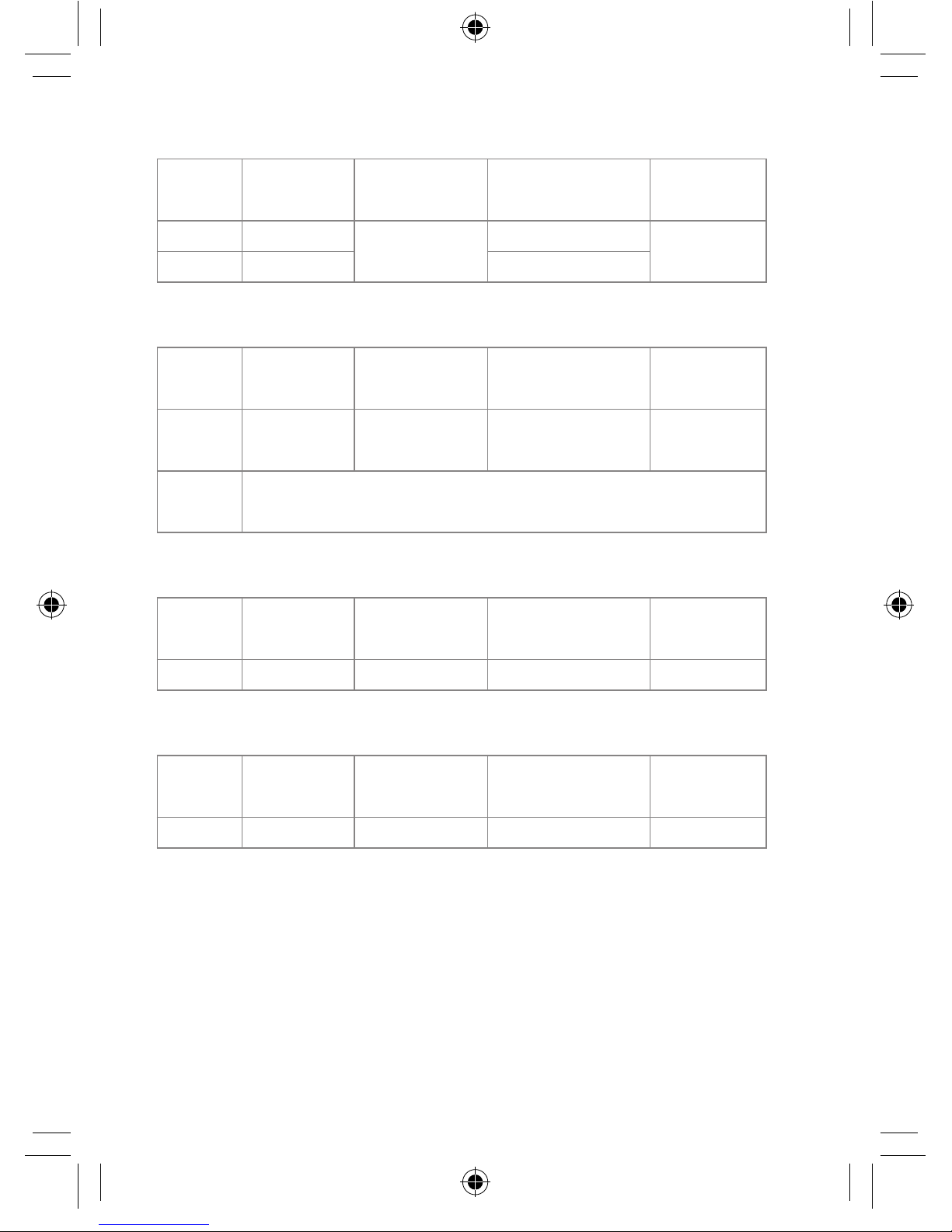
OHMS
Range Resolution Accuracy Max. open-circuit
voltage Overload
protection
40.00 Ω0.01 Ω±(1.2% +3) 5.8 V 250 Vrms
400.0 Ω0.1 Ω5.8 V
Continuity Beeper
Range Resolution Operation
resistance Max. open-circuit
voltage Overload
protection
•))) 0.01 ΩResistance
≤35 Ω5.8 V 250 Vrms
Short
circuit
current 200 mA
DC Voltage
Range Resolution Accuracy Input
impedance Overload
protection
1000 V 1 V ±(0.8% +3) 10 MΩ1000 Vrms
AC Voltage (40 Hz to 400 Hz)
Range Resolution Accuracy Input
impedance Overload
protection
750 V 1 V ±(1.2% +10) 10 MΩ750 Vrms
1065DGMAN_20250-60 DS Insulation tester manual.indd 13
8/7/2017 2:09:50 PM
14
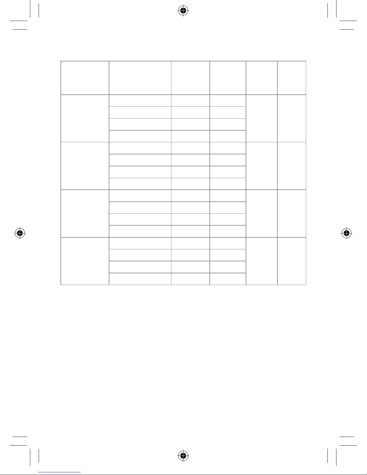
Meg OHMS
Terminal
voltage Range Resolution Accuracy Test
current
Short
circuit
current
125 V
(0% to +10%)
0.125 to 4.000 MΩ0.001 MΩ±(2% +10) 1 mA @
load
125 kΩ
≤1 mA
4.001 to 40.00 MΩ0.01 MΩ±(2% +10)
40.01 to 400.0 MΩ0.1 MΩ±(4% +5)
400.1 to 4000 MΩ1 MΩ±(5% +5)
250 V
(0% to +10%)
0.250 to 4.000 MΩ0.00 1MΩ±(2% +10) 1 mA @
load
250 kΩ
≤1 mA
4.001 to 40.00 MΩ0.0 1MΩ±(2% +10)
40.01 to 400.0 MΩ0.1 MΩ±(3% +5)
400.1 to 4000 MΩ1 MΩ±(4% +5)
500 V
(0% to +10%)
0.500 to 4.000 MΩ0.001 MΩ±(2% +10) 1 mA @
load
500 kΩ
≤1 mA
4.001 to 40.00 MΩ0.01 MΩ±(2% +10)
40.01 to 400.0 MΩ0.1 MΩ±(2% +5)
400.1 to 4000 MΩ1 MΩ±(4% +5)
1000 V
(0% to +10%)
1.000 to 4.000 MΩ0.001 MΩ±(3% +10) 1 mA @
load
1 MΩ
≤1 mA
4.001 to 40.00 MΩ0.01 MΩ±(2% +10)
40.01 to 400.0 MΩ0.1 MΩ±(2% +5)
400.1 to 4000 MΩ1 MΩ±(4% +5)
1065DGMAN_20250-60 DS Insulation tester manual.indd 14
8/7/2017 2:09:50 PM

15
Meg OHMS
Terminal
voltage Range Resolution Accuracy Test
current
Short
circuit
current
125 V
(0% to +10%)
0.125 to 4.000 MΩ0.001 MΩ±(2% +10) 1 mA @
load
125 kΩ
≤1 mA
4.001 to 40.00 MΩ0.01 MΩ±(2% +10)
40.01 to 400.0 MΩ0.1 MΩ±(4% +5)
400.1 to 4000 MΩ1 MΩ±(5% +5)
250 V
(0% to +10%)
0.250 to 4.000 MΩ0.00 1MΩ±(2% +10) 1 mA @
load
250 kΩ
≤1 mA
4.001 to 40.00 MΩ0.0 1MΩ±(2% +10)
40.01 to 400.0 MΩ0.1 MΩ±(3% +5)
400.1 to 4000 MΩ1 MΩ±(4% +5)
500 V
(0% to +10%)
0.500 to 4.000 MΩ0.001 MΩ±(2% +10) 1 mA @
load
500 kΩ
≤1 mA
4.001 to 40.00 MΩ0.01 MΩ±(2% +10)
40.01 to 400.0 MΩ0.1 MΩ±(2% +5)
400.1 to 4000 MΩ1 MΩ±(4% +5)
1000 V
(0% to +10%)
1.000 to 4.000 MΩ0.001 MΩ±(3% +10) 1 mA @
load
1 MΩ
≤1 mA
4.001 to 40.00 MΩ0.01 MΩ±(2% +10)
40.01 to 400.0 MΩ0.1 MΩ±(2% +5)
400.1 to 4000 MΩ1 MΩ±(4% +5)
1065DGMAN_20250-60 DS Insulation tester manual.indd 15
8/7/2017 2:09:50 PM

For Product and Ordering Information, Contact:
Toll-Free: 1-800-323-4340
Phone: 1-847-549-7600
Fax: 1-847-247-2929
ColeParmer.com/Digi-Sense
Toll-Free: 1-800-358-5525
Phone: 1-847-327-2000
Fax: 1-847-327-2700
Davis.com/Digi-Sense
Manual Part No. 00101-95
1065DGMAN_20250-60
1065DGMAN_20250-60 DS Insulation tester manual.indd 16
8/7/2017 2:09:50 PM
Table of contents
Other Digi-Sense Test Equipment manuals


Popular Test Equipment manuals by other brands


Tinker & Rasor
Tinker & Rasor CS-10 Product instructions

Data Video
Data Video VS-100 quick start guide

Vanguard
Vanguard EZCT-2KA user manual

AU Tool
AU Tool BST-100 user manual

Kyoritsu Electrical Instruments Works, Ltd.
Kyoritsu Electrical Instruments Works, Ltd. KEW6024PV instruction manual

Metrix
Metrix DOX 2 Series user guide