Global Test Supply Druck UPS-II User manual

GE
Sensing & Inspection Technologies
Druck UPS-II
Loop Calibrator
User manual - K0434
OUT
INT
OFF
LOOP
PWR
READ
EXT
UPS - II
mA
%
*
VALVE
LIN
FLOW
%
MA
STEPS
FIXED
loop calibrator
RANGES:
OUTPUT & READ 0 - 22.2 mA
PRESS * 2 SEC.TO DISPLAY MENU
SCROLL FUNCTIONS WITH KEY
PRESS *TO E NTER FUNCTION
PRESS *TO SELECT FIXED STEPS
USE OR TO ADJUST OUTPUT
a
Druck
a
ADruckCompany
www.GlobalTestSupply.com
Find Quality Products Online at: sales@GlobalTestSupply.com

Approved Service Agents
For the list of service centres visit our web site:
www.gesensinginspection.com
Symbols
This equipment meets the requirements of all
relevant European safety directives. The
equipment carries the CE mark.
Do not dispose of this product as household
waste. Use an approved organisation that
collects and/or recycles waste electrical and
electronic equipment. For more information:
Contact us at www.gesensinginspection.com
Battery Safety
This instrument is fitted with four size AA batteries either
rechargeable (nickel cadmium) or non-rechargeable
(alkaline).
Before storing this instrument remove the batteries.
When fitting batteries make sure the electrical contacts are
clean and observe the correct polarity.
The battery compartment should be inspected for corrosion
caused by leaking batteries. Corrosion must be removed
using approved methods*.
When storing and transporting batteries make sure that they
cannot be short circuited. A short-circuited battery can
become very hot and can, in certain circumstances, explode.
It is recommended that a suitable container is used for
storing and transporting batteries.
Dispose of old batteries using a safe, approved method.*
*Refer to the manufacturer for this information:
© General Electric Company. All rights reserved.
www.GlobalTestSupply.com
Find Quality Products Online at: sales@GlobalTestSupply.com

1 K0434 Issue No. 2
Introduction
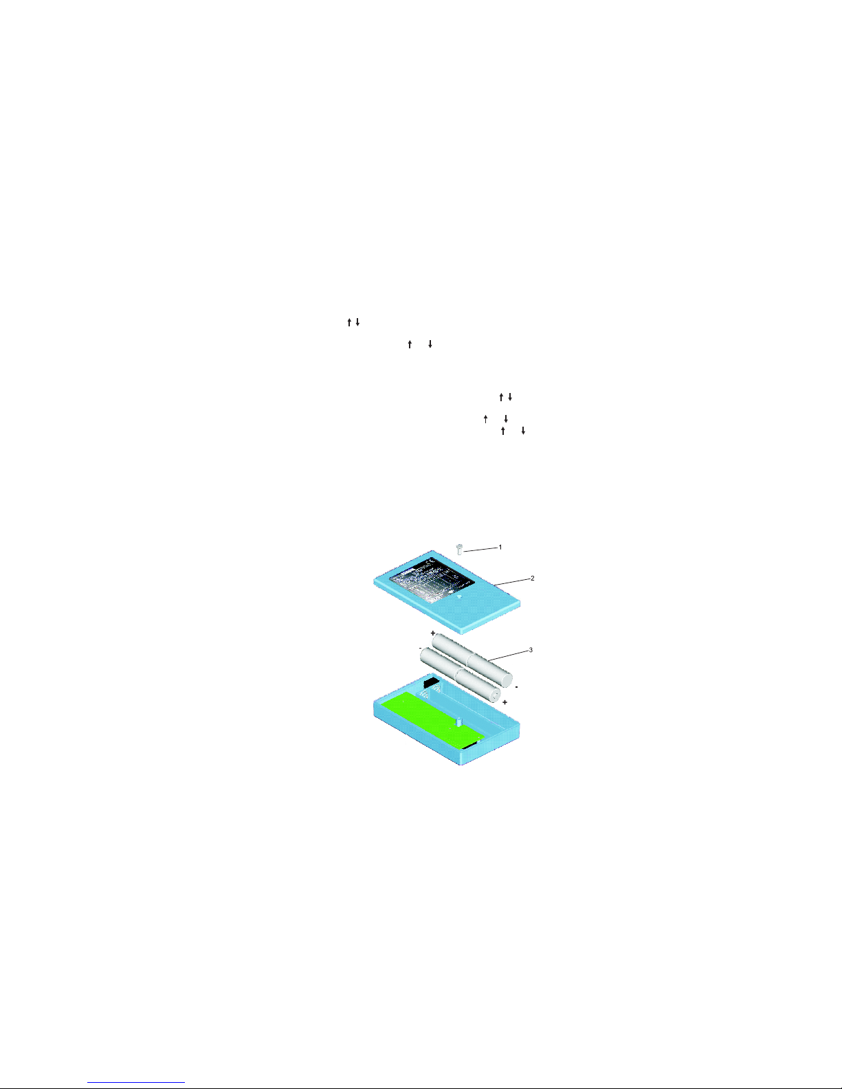
The Druck UPS-II Loop Calibrator can supply power (source
mode) and produce readings (measure mode) to perform
field calibrations on 2-wire devices.
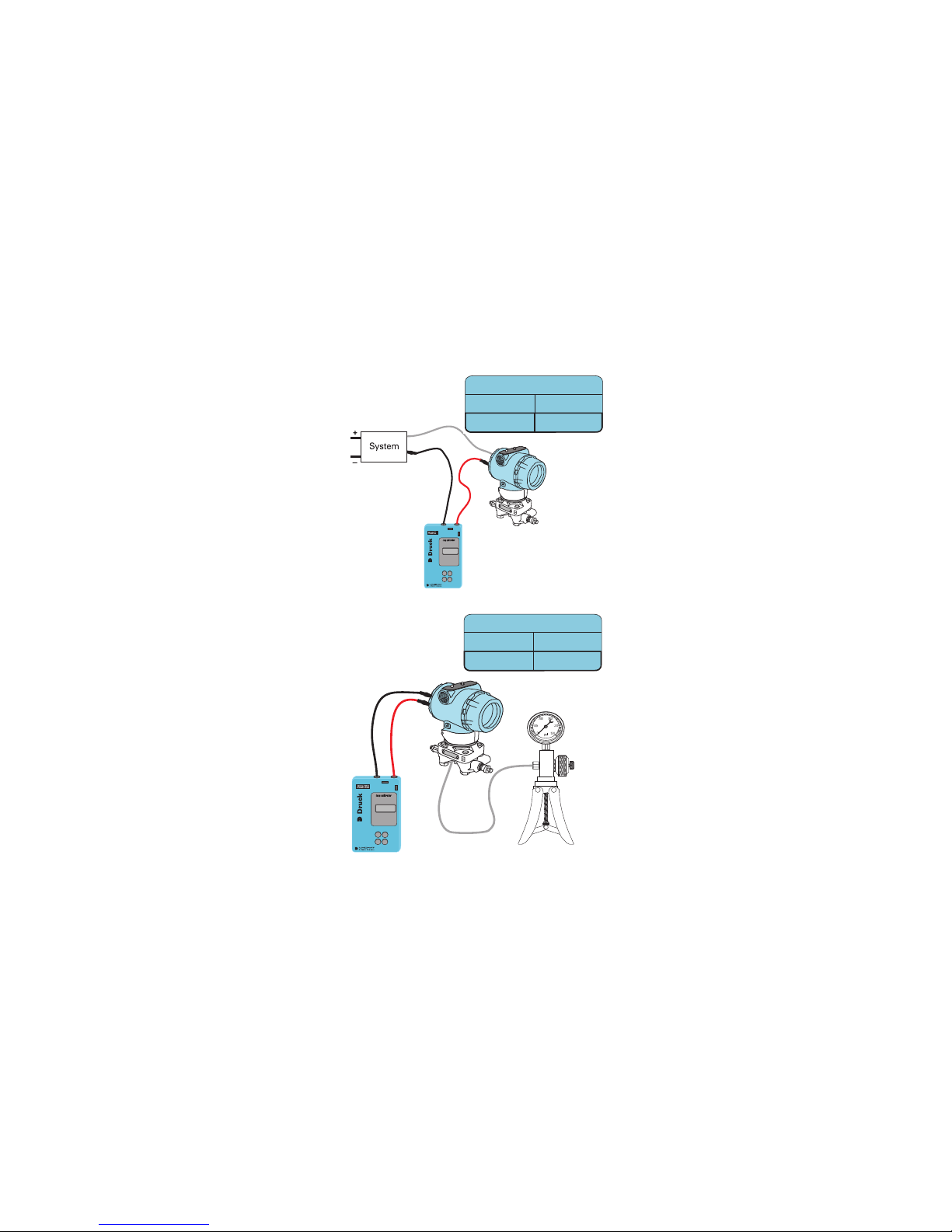
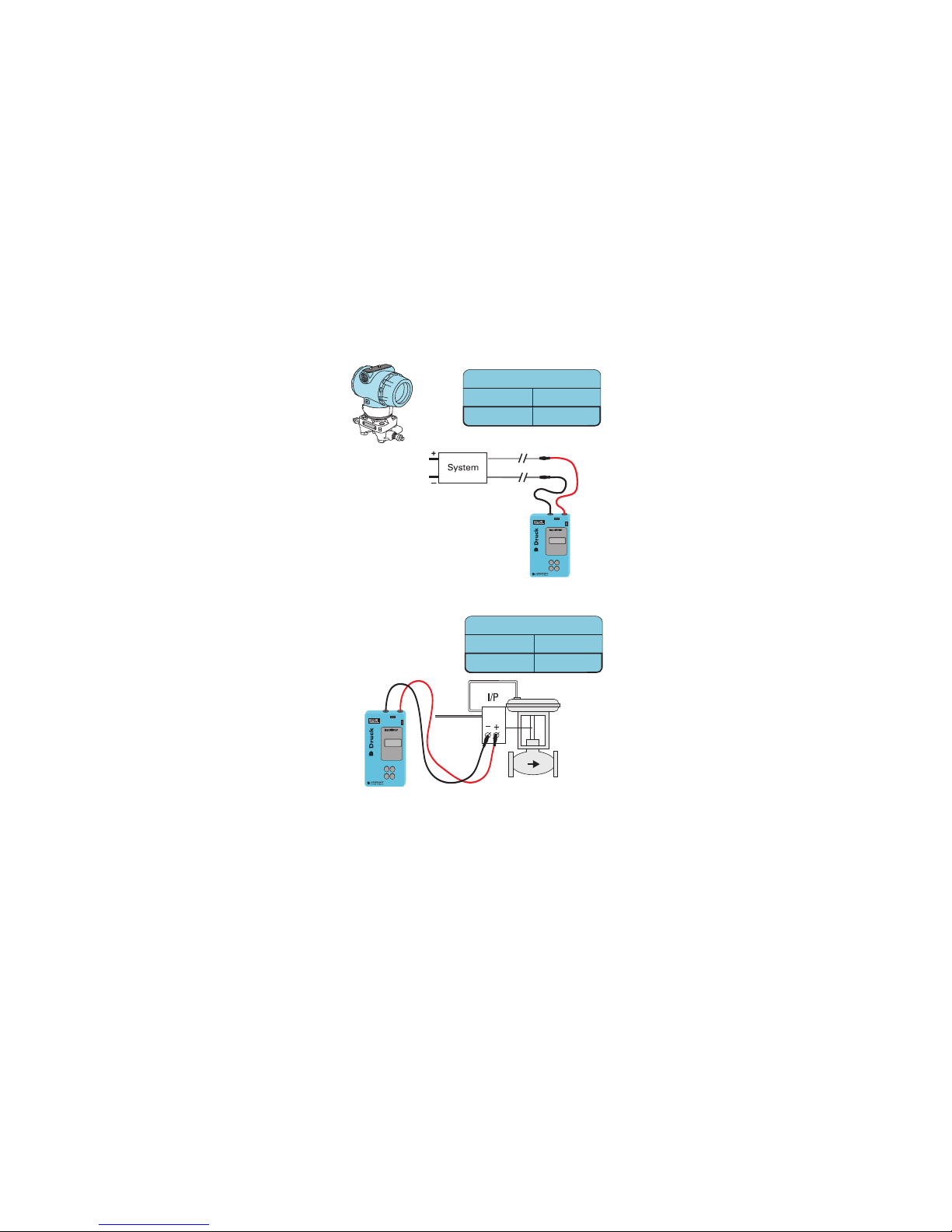
Operation
For different applications place switches in position as
indicated below:
(transmitters are 4-20mA 2 wire)
The UPS-II has special functions for fixed steps and readings
in %. To open menu press *for 2 seconds. Scroll menu
contents with key and make your choice. Press *again to
confirm your choice.
Note: Functions marked with # are directly available after
out
or
read
selection. Flow = SQ.RT in %.
Press mA/% key to read in mA or %. Press *to select
"continuous" or "fixed steps" in output mode.
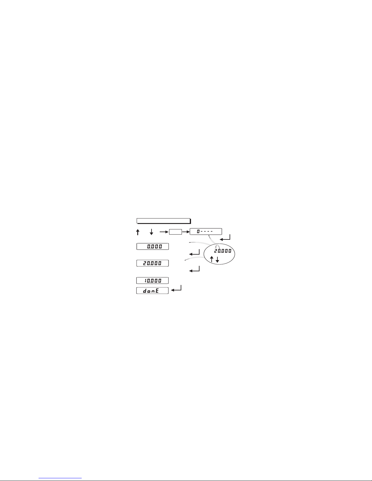
Fixed Steps
To output fixed calibration currents in series as indicated
below: choose range from the menu and select "fixed steps".
Press or to advance one step
MODE OUT READ EXT. INT.
Milliamp. source • •
Transmitter sim. • •
Milliamp measure • •
Transmitter cal. • •
MENU CHOICE SWITCH DISPLAY READING IN:
4-20mA lin # out 0 to 22mA or % span
0-20mA lin out 0 to 22mA or % span
4-20mA flow out 0 to 22mA or % span
0-20mA flow out 0 to 22mA or % span
4-20mA valve out 0 to 22mA
4-20mA lin # read 0 to 22mA or % span
0-20mA lin read 0 to 22mA or % span
4-20mA flow read 0 to 22mA or % span
0-20mA flow read 0 to 22mA or % span
4-20mA lin# 4 - 8 - 12 - 16 - 20mA
0-20mA lin 0 - 5 - 10 - 15 - 20mA
4-20mA flow 4 - 5 - 8 - 13 - 20mA
0-20mA flow 0 - 1,25 - 5 - 11,25 - 20mA
4-20mA valve 3,8-4-4,2 - 12 - 19 - 20 - 21mA
www.GlobalTestSupply.com
Find Quality Products Online at: sales@GlobalTestSupply.com

K0434 Issue No. 2
2
To output these currents automatically select "fixed steps"
and press keys simultaneously. Time between steps is
10 seconds. Stepping starts at the low end of span.
To return to manual press or .
Valve mode
In the valve mode, stepping will be 3,8 - 4 - 4,2 or 19 - 20 - 21
mA. Select appropriate current to start auto-stepping.
Ramp mode
To output a continuous up/down ramp cycle press keys
simultaneously. Ramp travel time between range limits is 60
seconds cycle starts at displayed value. Press or first
to select start direction. To return to manual press or .
Batteries
Use alkaline or rechargeable NiCad batteries only. The
display shows LOBAT when battery capacity goes low.
CAUTION
DONOT LEAVE DISCHARGED BATTERIES IN THE INSTRUMENT.
OLD BATTERIES CAN LEAK AND CAUSE CORROSION.
WHEN FITTING THE BATTERIES MAKE SURE THE ELECTRICAL CONTACTS
ARE CLEAN AND OBSERVE THE CORRECT POLARITY
1Centrescrew.
2Battery
compartment
cover.
3BatteriessizeAA
x4.
Replacement
Unscrew the
centre screw (1).
Remove the
cover (2).
Make sure the
polarity of the
new batteries (3)
is correct.
www.GlobalTestSupply.com
Find Quality Products Online at: sales@GlobalTestSupply.com

3 K0434 Issue No. 2
UPS-II Loop Calibrator Technical Notes
Current reading
Switch positions
Function Loop power
Read Ext.
Transmitter Calibration
Switch positions
Function Loop power
Read Int.
www.GlobalTestSupply.com
Find Quality Products Online at: sales@GlobalTestSupply.com

K0434 Issue No. 2
4
Transmitter Simulation
Switch positions
Function Loop power
Out Ext.
Valve Stroking
Switch positions
Function Loop power
Out Int.
www.GlobalTestSupply.com
Find Quality Products Online at: sales@GlobalTestSupply.com

5 K0434 Issue No. 2
Calibration Instructions
General
A calibration period of 12 months is recommended. The
actual calibration interval depends on instrument usage and
the total measurement uncertainty acceptable for the
specified application.
The
UPS-II
is a precise measuring instrument and the test
equipment and conditions of test must be suitable for the
type of work. The calibration check and calibration
adjustment should be carried out in a controlled
environment by a calibration technician*.
The manufacturer offers a comprehensive and, if required,
UKAS accredited calibration service.
*
A calibration technician must have the necessary technical knowledge,
documentation, special test equipment and tools to carry out the
calibration work on this equipment.
Calibration Equipment
The following tables give the accuracy requirements for the
calibration equipment and the UPS-II.
Calibration requires a stable temperature of 21° ±1°C (70° ±2°F).
UPS-II measure mode
Table 1
UPS-II source mode
Table 2
Applied
mA
Permitted UPS-II
error (mA)
Calibrator error
(mA)
0 0.007 0
4 0.007 0.00014
12 0.007 0.00030
20 0.007 0.00046
Applied
mA
Permitted UPS-II
error (mA)
Calibrator error
(mA)
00.01 0
4 0.01 0.00012
12 0.01 0.00011
20 0.01 0.00015
www.GlobalTestSupply.com
Find Quality Products Online at: sales@GlobalTestSupply.com

K0434 Issue No. 2
6
Calibration Check
1. Check the instrument for accuracy in measure and
source modes, if there is an error greater than the
permitted error, the instrument requires a calibration
adjustment.
Calibration Adjustment
Note:
For complete accuracy, the measure mode and source mode adjustment
must be carried together and in the following order.
Measure mode
1. Connect the UPS-II to the electrical calibrator. Switch on
the electrical calibrator and allow it to thermally
stabilise.
2. Switch on the UPS-II and allow the instrument to
thermally stabilise.
3. Select EXT on the LOOP PWR slide switch. Use the
display menu to select the calibration values:
Calibration Procedure mA Input
2 seconds
Apply zero - open circuit test leads
Connect test leads to mA source
apply full-scale
Adjust mA source to any
value within range - check reading
example
serial number
READ
and
+
Enter
*
Enter
*
Enter
*
VALVE
LIN
FLOW
MA
VALVE
LIN
FLOW
MA
and
+
-
*
adjust each
digit
adjust each digit
adjust each digit
Enter
*
Input calibration complete new offset values stored
continue with output calibration.
VALVE
LIN
FLOW
MA
www.GlobalTestSupply.com
Find Quality Products Online at: sales@GlobalTestSupply.com

7 K0434 Issue No. 2
Source mode
1. Connect the UPS-II to the electrical calibrator. Switch on
the electrical calibrator and allow it to thermally
stabilise.
2. Switch on the UPS-II and allow the instrument to
thermally stabilise.
3. Select INT on the LOOP PWR slide switch. Use the
display menu to select the calibration values:
Completion
1. Switch off and disconnect the calibration equipment.
2. Update the calibration records for the instrument.
Calibration Procedure mA Output
2 seconds
Connect test leads to mA-meter
compare values.
serial number
OUT
and +
Enter
*
Enter
*
Enter
*
Enter
*
Enter
*
and
+
-
*
adjust each
digit
adjust each digit
adjust each digit
Calibration complete new output values stored
Compare values.
Check reading.
Check reading.
VALVE
LIN
FLOW
MA
VALVE
LIN
FLOW
MA
VALVE
LIN
FLOW
MA
VALVE
LIN
FLOW
MA
www.GlobalTestSupply.com
Find Quality Products Online at: sales@GlobalTestSupply.com

K0434 Issue No. 2
8
Specifications
Range........................................................................................ 0 to 22.2 mA
Accuracy........................................................................ 0,05% of range
Resolution...................................................................... 10 microamps
Temperature effect.............................. 0,003%/°C - 0,0015%/°F
Internal loop power...................................................24 VDC stabilized
External loop power............................................................48 VDC max.
Measurement input................................................... 12 ohms fused
Drive capability..................................................................... 900 ohms
Operating temperature............ -10°C to 50°C - 14°F to 122°F
Storage temperature .............. -20°C to 60°C - -4°F to 140°F
Battery......................... 4 x 1.5V alkaline or rechargeable size AA
Battery life (alkaline)............................. source 12mA; 18 hours
................................................................................. measure 900 hours
Loop mismatch........................................................... flashes "LOOP"
Low battery................................................................... flashes "LOBAT"
Over-range.................................................................... flashes "EEEE"
Reversed polarity....................................................... flashes "POL"
Adaptor line/6VDC
230V/50Hz............................ part numbers - UNO-13600-1 (UK)
...................................................................... - UNO-13600-2 (Europe)
110V/60Hz............................ part number - UNO-13600-3 (USA)
Housing.......................................................................... high impact ABS
Size................................................................................... 3" x 5" x 0,83"
................................................................................. 77 x 124 x 21 mm
Weight .................................................................. 212 grams - 7.5 oz
................................................................................. (including batteries)
www.GlobalTestSupply.com
Find Quality Products Online at: sales@GlobalTestSupply.com
Table of contents