Digiflex CM430S How to use

Installer
Reference Guide
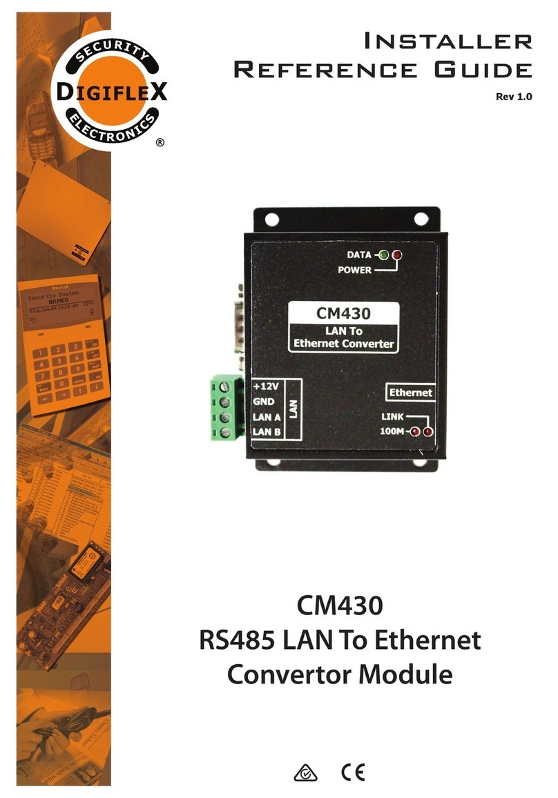
CM430S
RS485 LAN To Ethernet
Converter Module
Rev 1.2
®

Page 2 P/N: CM430SIRG Rev 1.2 E&OE Copyright © 2019
The CM430S allows you to extend the control panels RS485S LAN across a local network. Table 1: shows the panel
and panel firmware which are compatible with the CM430S converter module. MENU 7-7-0, Option 5 (Extend LAN
Fail) must be set when using the CM430S.
CM430S Compatibility
Panels Supported Version
Solution 6000 V2.29 or higher
Table 1: CM430S Compatibility
i
Note
MENU 7-7-0, Option 5 (Extend LAN Fail) must be set when
using the CM430S.
LED Status
The following LED indicators are provided on the CM430S module.
LED Colour Activity Description
Active Green / Blue Blue Data sent from Ethernet to Serial
Green Data sent from Serial to Ethernet
LINK Green/Blue Blue Connection Established
Green Ethernet Cable connected
Power RED Off Power OFF
On Power ON
Table 2: LED Indicators
Initial Setup
Using a stand alone computer (your PC must have an Ethernet port), you can connect your computer directly to
the CM430S using a crossover Ethernet cable. Otherwise, connect both the computer and CM430S using straight-
through Ethernet cable to a hub or switch (Ensure computers adapter is set to the same base address, ie: 192.168.1.1,
See page 7 - Windows IP Configuration.).
Quick Setup With Fixed IP
The CM430S has the following default settings.
Option Default Setting
IP Address (Factory) 192.168.1.200
IP Address (Default Switch) 192.168.1.254
Subnet Mask 255.255.255.0
Gateway 192.168.1.1
Primary DNS 192.168.1.3
Connection Mode TCP Server
Connection Port Number 5000
Remote Host IP Address 0.0.0.0
Table 3: Quick Setup With Fixed IP
CM430S - RS485 LAN To Ethernet
Converter Module
The following LED indicators are provided on the CM430S module.

P/N: CM430SIRG Rev 1.2 Page 3
Copyright © 2019 E&OE
CM430S Configuration (Point to Point)
Connect a module to your computer and power the module using 12VDC.
Open your browser and enter 192.168.1.200 (Factory set) and press [Enter].
If the unit is reset by the user, then its default address will be 192.168.1.254
A window will be displayed prompting you to enter the password (default = 123456).
After entering the password, the web browser page will be displayed..
Figure 1: Point to Point - Location 1
Figure 2: Point to Point - Location 2

Page 4 P/N: CM430SIRG Rev 1.2 E&OE Copyright © 2019
The CM430S module closest to the panel (Location 1) has to be set to ‘TCP Server’ and have its ‘Remote Host IP Ad-
dress’ set to the IP address of the Remote CM430S unit. The table below is an example of configuring both the Client
and Server modules.
Option Location 1
SERVER
Location 2
CLIENT
Device IP 192.168.1.5 192.168.1.6
Subnet Mask 255.255.255.0 255.255.255.0
Gateway 192.168.1.5 192.168.1.5
Primary DNS 168.95.1.1 168.95.1.1
Work Mode TCP SERVER TCP CLIENT
Destination Port 4196 4196
Destination IP/DNS 192.168.1.5 192.168.1.5
IP Mode Static Static
Table 4: Example Point to Point Configuration
After all settings have been complete, click‘Apply’ and the changes will take effect. Note: It is best to power cycle the
module after any changes.
Connection Diagram - Point to Point Configuration
A pair of CM430S modules is required for each link as shown below. Remote locations will require a local power
supply wih backup battery to maintain connectivity during power outages. A CM720 1 amp or CM723 5 amp power
supply module would be suitable for this task.
Ethernet
GND
+12V
LAN A
LAN A
LAN B
LAN B
IN OUT
Not Used
Reset Protect
Type: Static IP
IP Address: 192168.1.6
Connection Mode: TCP Client
Location 2
RS232
GND
+12V
LAN A
LAN A
LAN B
LAN B
IN OUT
Module LAN
B A -+
Not Used
Reset Protect
Type: Static IP
IP Address: 192168.1.5
Connection Mode: TCP Server
Location 1
RS232
Not Used
GND
+12V
LAN A
LAN A
LAN B
LAN B
IN OUT
Module LAN
B A -+
Not Used
Reset Protect RS232
GND
+12V
LAN A
LAN A
LAN B
LAN B
IN OUT
Module LAN
B A -+
Not Used
Reset Protect RS232
Ethernet
GND
+12V
LAN A
LAN A
LAN B
LAN B
IN OUT
PANEL LAN
B A -+
Not Used
Reset Protect RS232
Module LAN
B A -+
Not Used
Local
Power Supply
/ Battery
Figure 3: Sample Point to Point Wiring
NOTE: LAN A OUT, LAN B OUT and
the Protect Switch are for Future Use

P/N: CM430SIRG Rev 1.2 Page 5
Copyright © 2019 E&OE
CM430S Star Configuration
An array of CM430S modules can be used if more then one locations is needed. This configuration will need to go
through a LAN switch that has a backup power supply. Each Remote location will require a local power supply with
backup battery to maintain connectivity during power outages. A CM720, 1 amp or CM723, 5 amp power supply
module would be suitable for this task.
Figure 4: Sample Star Configuration - Location 1
Figure 5: Sample Star Configuration - Locations 2 -17

Page 6 P/N: CM430SIRG Rev 1.2 E&OE Copyright © 2019
Option Location 1
SERVER
Location 2
CLIENT
Location 3
CLIENT
Location 4
CLIENT
Device IP 192.168.1.5 192.168.1.6 192.168.1.7 192.168.1.8
Subnet Mask 255.255.255.0 255.255.255.0 255.255.255.0 255.255.255.0
Gateway 192.168.1.5 192.168.1.5 192.168.1.5 192.168.1.5
Primary DNS 168.95.1.1 168.95.1.1 168.95.1.1 168.95.1.1
Work Mode TCP Server TCP Client TCP Client TCP Client
Destination Port 4196 4196 4196 4196
Destination IP/DNS 192.168.1.5 192.168.1.5 192.168.1.5 192.168.1.5
IP Mode Static Static Static Static
Table 5: Star Configuration Example Settings
Connection Diagram - Star Configuration
Figure 6: Sample Star Configuration Wiring
LAN Switch
Ethernet
GND
+12V
LAN A
LAN A
LAN B
LAN B
IN OUT
Not Used
Reset Protect
Type: Static IP
IP Address: 192168.1.6
Connection Mode: TCP Client
Location 2
RS232
GND
+12V
LAN A
LAN A
LAN B
LAN B
IN OUT
Module LAN
B A -+
Not Used
Reset Protect
Type: Static IP
IP Address: 192168.1.5
Connection Mode: TCP Server
Location 1
RS232
Not Used
GND
+12V
LAN A
LAN A
LAN B
LAN B
IN OUT
Module LAN
B A -+
Not Used
Reset Protect RS232
GND
+12V
LAN A
LAN A
LAN B
LAN B
IN OUT
Module LAN
B A -+
Not Used
Reset Protect RS232
Ethernet
GND
+12V
LAN A
LAN A
LAN B
LAN B
IN OUT
PANEL LAN
B A -+
Not Used
Reset Protect RS232
Module LAN
B A -+
Not Used
Local
Power Supply
/ Battery
Local
Power Supply
/ Battery
Ethernet
GND
+12V
LAN A
LAN A
LAN B
LAN B
IN OUT
Not Used
Reset Protect
Type: Static IP
IP Address: 192168.1.7
Connection Mode: TCP Client
Location 3
RS232
Module LAN
B A -+
Not Used
Local
Power Supply
/ Battery
GND
+12V
LAN A
LAN A
LAN B
LAN B
IN OUT
Module LAN
B A -+
Not Used
Reset Protect
Type: Static IP
IP Address: 192168.1.8
Connection Mode: TCP Client
Location 4
RS232
Not Used
GND
+12V
LAN A
LAN A
LAN B
LAN B
IN OUT
Module LAN
B A -+
Not Used
Reset Protect RS232
GND
+12V
LAN A
LAN A
LAN B
LAN B
IN OUT
Module LAN
B A -+
Not Used
Reset Protect RS232
Ethernet
GND
+12V
LAN A
LAN A
LAN B
LAN B
IN OUT
Module LAN
B A -+
Not Used
Reset Protect RS232
Local
Power Supply
/ Battery
NOTE: LAN A OUT, LAN B OUT and
the Protect Switch are for Future Use

P/N: CM430SIRG Rev 1.2 Page 7
Copyright © 2019 E&OE
Windows IP Configuration
Click on Start button and choose Settings.
1. Choose Network & Internet.
2. Click on Ethernet -> Change adapter options. ...
3. Click Internet Protocol Version 4 (TCP/IPv4), and then click Properties. ...
Warning:
Before changing any of the numbers, ensure you take note of the original settings, as
this will disconnect you from your normal network connection.
Digiflex does not take any responsibility for your PC configuration, if you are
not experienced in networking, please contact your IT person.
Figure 7: Windows PC IP Config Setup Page
CM430S Reset
The CM430S modules can be reset whilst powered up by using a thin screwdriver and sliding the Reset switch from
OFF to ON position, then after 2-3 seconds, back to the OFF position. This will reset the device IP to 192.168.1.254
CM430S Specifications
Part Number: CM430S - RS485 LAN To Ethernet Module - Supporting Star Configuration
Operating Voltage: 10.5V D.C - 14.5V D.C. @ 150mA Max
Module Connection:
(RS485 LAN)
Ethernet Interface: 10 / 100Base-T, Half / Full Duplex
RS485 Signal: 2 wire Data+/-
Operating
Environment: 0˚ to 55˚C RH 5 to 80% at 30˚C non-condensing.
Certification: EN55032:2012, EN55024: 2010.A1:2015,
EN61000-3-2:2014, EN61000-2-2:2013
Warranty: 3 years from date of manufacture (return to base).
In the interest of ongoing product development this
document is subject to change without notice.

Copyright ©2002-2019 Digiflex Pty Ltd
P/N : CM430SIRG
DIGIFLEXPTY LTD
Unit 5, 8 Millennium Court
Silverwater NSW 2128
AUSTRALIA
Phone: (+612) 97417000
Facsimile: (+612) 97417042
www.digiflex.com.au
Our Vision Is Your Peace Of Mind
Table of contents
Other Digiflex Media Converter manuals
Popular Media Converter manuals by other brands
SightLine
SightLine 3000-OEM quick start guide

Samson
Samson 6111 Mounting and operating instructions

Patton electronics
Patton electronics 2300M user manual
Advantech
Advantech B+B SmartWorx Giga-MiniMc 856-10730-TX user manual

VBrick
VBrick 9000 Series Getting started guide
Onkyo
Onkyo RBX-500 instruction manual
