Samson 6111 Service manual

Translation of original instructions
EB 6111 EN
Edition September 2017
Type 6111 in standard version Type 6111 mounted on a supply air
manifold
Type 6111 in eld enclosure
Type6111 i/p Converter
Electropneumatic Converters for Direct Current Signals

Note on these mounting and operating instructions
These mounting and operating instructions assist you in mounting and operating the device
safely. The instructions are binding for handling SAMSON devices.
ÎFor the safe and proper use of these instructions, read them carefully and keep them for
later reference.
ÎIf you have any questions about these instructions, contact SAMSON‘s After-sales Service
Department (aftersalesser[email protected]).
The mounting and operating instructions for the devices are included in
the scope of delivery. The latest documentation is available on our website
at www.samson.de > Service & Support > Downloads > Documentation.
Denition of signal words
Hazardous situations which, if not avoided,
will result in death or serious injury
Hazardous situations which, if not avoided,
could result in death or serious injury
Property damage message or malfunction
Additional information
Recommended action
DANGER
!
WARNING
!
NOTICE
!
Note
Tip
2 EB 6111 EN

Contents
EB 6111 EN 3
1 Safety instructions and measures ...................................................................5
1.1 Notes on possible severe personal injury .........................................................7
1.2 Notes on possible personal injury ...................................................................8
1.3 Notes on possible property damage................................................................8
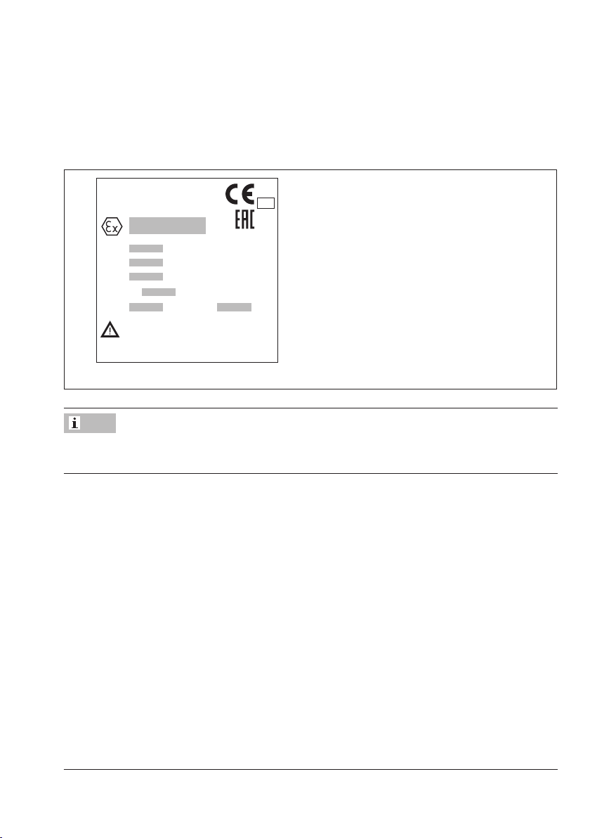
2 Markings on the device .................................................................................9
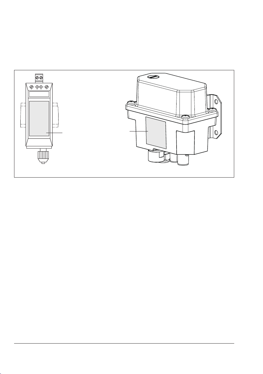
2.1 Nameplate ....................................................................................................9
2.2 Article code.................................................................................................10
3 Design and principle of operation ................................................................12
3.1 Versions ......................................................................................................14
3.2 Technical data .............................................................................................16
3.3 Accessories .................................................................................................20
4 Measures for preparation............................................................................22
4.1 Unpacking ..................................................................................................22
4.2 Transporting and lifting ................................................................................22
4.3 Storage.......................................................................................................22
4.4 Preparation for installation............................................................................22
5 Mounting and start-up.................................................................................24
5.1 Installing i/p converters................................................................................24
5.1.1 Installing the rail-mounting unit .....................................................................24
5.1.2 Installing the eld unit...................................................................................24
5.2 Electrical connection.....................................................................................24
5.3 Pneumatic connection...................................................................................25
5.3.1 Connecting the rail-mounting unit..................................................................25
5.3.2 Connecting the eld unit...............................................................................25
5.4 Mounting the supply air manifold for rail-mounting units.................................25
5.4.1 Fastening the supply air manifold..................................................................26
5.4.2 Assembling the supply air manifold...............................................................26
5.4.3 Connecting several supply air manifolds ........................................................26
5.4.4 Mounting the i/p converter on the manifold ...................................................28

Contents
4 EB 6111 EN
6 Operation...................................................................................................30
6.1 Checking zero and span...............................................................................30
6.1.1 Checking zero .............................................................................................30
6.1.2 Checking span.............................................................................................32
6.2 Zero adjustment (versions with 0 to 20mA input signal)..................................32
7 Servicing.....................................................................................................33
7.1 Servicing explosion-protected devices............................................................33
8 Troubleshooting...........................................................................................34
9 Decommissioning and disassembly ..............................................................36
9.1 Removing the i/p converters .........................................................................36
9.1.1 Removing the rail-mounting unit....................................................................36
9.2 Removing the eld unit .................................................................................36
9.3 Disposal......................................................................................................36
10 Annex.........................................................................................................37
10.1 After-sales service........................................................................................37
10.2 Certicates ..................................................................................................37

EB 6111 EN 5
Safety instructions and measures
1 Safety instructions and measures
Intended use
The Type6111 i/p Converter is used to convert a direct current input signal into a pneumatic
output signal for measuring and control tasks. The i/p converter is particularly suitable as an
intermediate element between electric measuring devices and pneumatic controllers or be-
tween electric control devices and pneumatic control valves.
The device is designed to operate under exactly dened conditions (e.g. input signal, pres-
sure). Therefore, operators must ensure that the device is only used in applications that meet
the specications used for sizing the device at the ordering stage. In case operators intend to
use the device in other applications or conditions than specied, contact SAMSON.
SAMSON does not assume any liability for damage resulting from the failure to use the de-
vice for its intended purpose or for damage caused by external forces or any other external
factors.
ÎRefer to the technical data and nameplate for limits and elds of application as well as
possible uses.
Reasonably foreseeable misuse
The device is not suitable for use outside the limits dened during sizing and by the technical
data. Furthermore, the following activities do not comply with the intended use:
−Use of non-original spare parts
−Performing service and repair work not described in these instructions
Qualications of operating personnel
The device must be mounted, started up, serviced and repaired by fully trained and qualied
personnel only; the accepted industry codes and practices are to be observed. According to
these mounting and operating instructions, trained personnel refers to individuals who are
able to judge the work they are assigned to and recognize possible hazards due to their spe-
cialized training, their knowledge and experience as well as their knowledge of the applica-
ble standards.

6 EB 6111 EN
Safety instructions and measures
Personal protective equipment
We recommend checking the hazards posed by the plant and the process medium being
used (e.g. uGESTIS (CLP) hazardous substance database).
ÎProvide protective equipment (e.g. safety gloves, eye protection) appropriate for the ma-
terial safety data sheet.
ÎCheck with the plant operator for details on further protective equipment.
Revisions and other modications
Revisions, conversions or other modications to the product are not authorized by SAMSON.
They are performed at the user's own risk and may lead to safety hazards, for example. Fur-
thermore, the product may no longer meet the requirements for its intended use.
Warning against residual hazards
To avoid personal injury or property damage, operators and operating personnel must pre-
vent hazards that could be caused in the device by the process medium and operating pres-
sure by taking appropriate precautions. They must observe all hazard statements, warning
and caution notes in these mounting and operating instructions, especially for installation,
start-up and service work.
Responsibilities of the operator
The operator is responsible for proper operation and compliance with the safety regulations.
Operators are obliged to provide these mounting and operating instructions as well as the
referenced documents to the operating personnel and to instruct them in proper operation.
Furthermore, the operator must ensure that operating personnel or third persons are not ex-
posed to any danger.
Responsibilities of operating personnel
Operating personnel must read and understand these mounting and operating instructions as
well as the referenced documents and observe the hazard statements, warning and caution
notes specied in them. Furthermore, the operating personnel must be familiar with the ap-
plicable health, safety and accident prevention regulations and comply with them.

EB 6111 EN 7
Safety instructions and measures
Referenced standards and regulations
Devices with a CE marking have an EU declaration of conformity, which includes information
about the applied conformity assessment procedure. This EU declaration of conformity is in-
cluded in the appendix of these instructions (see section10.2).
For electrical installation, observe the relevant electrotechnical regulations and the accident
prevention regulations that apply in the country of use. In Germany, these are the VDE regu-
lations and the accident prevention regulations of the employers’ liability insurance.
For installation in hazardous areas, observe the relevant standards that apply in the country
of use. Standard applicable in Germany: EN60079-14: 2008 (VDE0165, Part1) Explosive
Atmospheres– Electrical Installations Design, Selection and Erection.
The maximum permissible values specied in the EC type examination certicates apply
when interconnecting intrinsically safe electrical equipment (Uior U0, lior I0, Pior P0, Ci or C0
and Li or L0).
Referenced documentation
The following documents apply in addition to these mounting and operating instructions:
−Version as eld unit: the mounting and operating instructions of the components on which
the i/p converter is mounted (valve, actuator, valve accessories, etc.)
−Safety Manual uSH6111 for use in safety-instrumented systems
1.1 Notes on possible severe personal injury
DANGER
!
Risk of fatal injury due to the formation of an explosive atmosphere.
Incorrect installation, operation or maintenance of the i/p converter in potentially explo-
sive atmospheres may lead to ignition of the atmosphere and cause death.
ÎThe following regulations apply to installation in hazardous areas: EN60079-14
(VDE0165, Part1).
ÎInstallation, operation or maintenance of the i/p converter must only performed by
personnel who has undergone special training or instructions or who is authorized
to work on explosion-protected devices in hazardous areas.

8 EB 6111 EN
Safety instructions and measures
1.2 Notes on possible personal injury
WARNING
!
The i/p converter poses no hazard with possible personal injury.
ÎCheck with the plant operator for details on possible personal injury which could
be caused by the plant and ambient conditions (e.g. process medium, tempera-
ture).
1.3 Notes on possible property damage
NOTICE
!
A zero shift may occur due to shocks.
Shocks can cause a zero shift which impairs the correct functioning.
ÎProtect the device against external inuences (e.g. impact, shocks).
ÎCheck zero, if necessary (see section6).
Risk of malfunction due to failure to comply with required air quality.
An insufcient air quality may lead to the output signal not being proportional to the
input signal.
ÎMake sure that the air quality complies with the requirements (see section3.2).
ÎCheck the air lter and separator installed in the upstream air reducing station reg-
ularly.

EB 6111 EN 9
Markings on the device
2 Markings on the device
2.1 Nameplate
0102
SAMSON 6111
i/p Converter
Input
Output
Supply
Model 6111-
Var-ID Serial no.
* See technical data and explosion-protection
and maximum values.
certificate for permissible ambient temperature
SAMSON AG 60314 Frankfurt Made in Germany
1
5
4
6
3
2
7
1Explosion protection specications
2Input signal (electric)
3Output signal (pneumatic)
4 Supply pressure
5Model no.
6Conguration ID
7 Serial number
Fig.1: Nameplate of an explosion-protected eld unit
The Type6109 and Type6112 i/p Modules have their own nameplate, which differs from
the nameplate on the i/p converter.
Note

10 EB 6111 EN
Markings on the device
Location of the nameplate
The nameplate of the rail-mounting unit is lasered onto the front cover. The nameplate of the
eld unit is afxed to the eld housing.
ZERO + _SPAN
Nameplate Nameplate
Fig.2: Version as rail-mounting unit Fig.3: Version as eld unit
2.2 Article code
The article code is listed on the next page.

EB 6111 EN 11
Markings on the device
Order no. Type6111- xxxxxxxxxxxxxxxx
Explosion
protection
Without 0
II 2 GExia IIC T6 according to ATEX 1
II 3 GEx nA II T6 according to ATEX4) 8
Housing For rail mounting, 35mm top-hat rail
(DINEN60715) 0
Field housing in stainless steel 1.4581 1
i/p module Type6109 1
Type6112 2
Input 4 to 20mA with switch-off electronics 0 1
0 to 20mA without switch-off electronics 1) 202
4 to 12mA with switch-off electronics 203
12 to 20mA with switch-off electronics 204
Volume
booster
I (output from 0.1bar/3psi) 1
II (output from 0bar/0psi) 2) 2 2
Output 0.2 to 1.0bar 101
3 to 15psi 102
0.4 to 2.0bar 2 1 0 3
6 to 30psi 2 1 0 4
Special
ranges
3)
Initial value
5)
Span ∆p
0.1 to 0.4bar 0.75 to 1.00bar 2 1 1
0.1 to 0.4bar 1.00 to 1.35bar 2 1 2
0.1 to 0.4bar 1.35 to 1.81bar 2 1 3
0.1 to 0.8bar 1.81 to 2.44bar 2 1 4
0.1 to 0.8bar 2.44 to 3.28bar 2 1 5
0.1 to 0.8bar 3.28 to 4.42bar 2 1 6
0.1 to 1.2bar 4.42 to 5.94bar 2 1 7
0.1 to 1.2bar 5.94 to 8.00bar 2 1 8
Direction of
action
Increasing/increasing 1
Increasing/decreasing 2 2
Pneumatic
connection
For hose with 4mm inside diameter and
6mm outside diameter (screwed hose
connection M10x1)
0 0
1
/
8
“ - 27NPT female thread 0 1
ISO-228/G
1
/
8
female thread 0 2
M5 female thread 0 3
¼“ - 18NPT 1 4
Electrical
connection
For 0.5 to 2.5mm² terminals 0 1
Angle connector acc. to DINEN175301-803
0 2
M20x1.5 1 3
Degree of
protection
IP20 0 1
IP65 1 2
Temperature Tmin ≥–20°C 0
Sp. version Without 0 0 0
1) Without switch-off electronics and without potentiometer for zero point correction and explosion-protected device
without potentiometer for span correction
2) A relatively stable supply air network is required for the special version with volume booster II.
3) Specify setting range, e.g. set to 0.1 to 4 bar; output pressure max. 8 bar, supply air 10bar
4) For Ex nA the rail-mounting unit must be installed in an enclosure with minimum degree of protection IP54 (see sec-
tion10.2)
5) Initial value raised up to 3.0 bar (special version 300 and 301)

12 EB 6111 EN
Design and principle of operation
3 Design and principle of oper-
ation
The Type6111 i/p Converter is used to con-
vert a direct current input signal into a pneu-
matic output signal for measuring and con-
trol tasks. The i/p converter consists of an
Type6109 or Type6112 i/p Module and a
downstream volume booster.
The i/p converter is available as a
rail-mounting unit or eld unit (see sec-
tion3.1).
The input is a load-independent direct cur-
rent of 4 to 20mA or 0 or 20mA. The out-
put is a pneumatic signal of 0.2 to 1bar or
other signal ranges up to max. 8bar.
Principle of operation (see Fig.6)
When operated, the supplied direct current i
ows through the plunger coil (2) located in
the eld of a permanent magnet (3). At the
balance beam (1), the force of the plunger
coil, which is in proportion to the current, is
balanced against the force of the dynamic
backpressure pK, which is produced on the
apper (6) by the air jet leaving the nozzle
(7). The supply air (9) ows to the bottom
chamber of the volume booster (8) and a
certain amount of air determined by the dia-
phragm position ows past the sleeve (8.5)
and leaves through the output (OUTPUT 36).
The output signal pAis used also to supply
the nozzle (7). The offset spring (8.2) ensures
that the output signal is at least 100mbar
even at an input signal of 0mA. As the input
current and the forces acting on the plunger
coil increase, the apper (6) moves closer to
the nozzle (7). This causes the backpressure
pK upstream of the restriction (8.4) to rise.
The cascade pressure increases until it corre-
sponds with the input current.
Fig.4: Rail-mounting unit Fig.5: Field unit with stainless steel housing

EB 6111 EN 13
Design and principle of operation
1.1
1
2
3
4
i
5
OUTPUT 36
8.4
8
8.2
8.3
8.5
SUPPLY 9
pA
SPAN
+–
7
6
pK
ZERO
Type6109/6112
i/p Module
Version with volume booster I
1Balance beam
1.1 Mechanical zero point
adjuster (0 to 20mA
version only)
2Plunger coil
3Permanent magnet
4 Zero point and span
adjusters (not in 0 to
20mA version)
5Slide switch for switch-
off electronics (not in 0
to 20mA version)
6 Flapper
7Nozzle
8 Volume booster
8.2 Offset spring
8.3 Diaphragm
8.4 Restriction
8.5 Plug sleeve (venting)
8.6 Fixed restriction
9Springs
pAOutput pressure
pKBackpressure (cascade
pressure)
Supply air
6
7
8
8.3
8.6
8.5
1
2
3
4
i
SUPPLY 8
OUTPUT 36
pA
ZERO SPAN
+ –
pK
Type6112
i/p Module
Version with volume booster II
Fig.6: Functional diagram

14 EB 6111 EN
Design and principle of operation
The increasing backpressure pushes the dia-
phragm (8.3) and the plug sleeve (8.5)
downwards. As a result, the supply air caus-
es the output pressure pA to increase until a
new state of equilibrium is reached in the di-
aphragm chambers.
When the backpressure pK drops, the dia-
phragm moves upwards, releasing the plug
sleeve. The output pressure pA can escape
through the sleeve until the forces are equal
again.
3.1 Versions
The nameplate and article code provide de-
tails on the device version (see section2).
Rail-mounting unit
The i/p converter is designed for mounting
on a top-hat rail.
Optionally, mount it to a wall using the two
Ø 5.5mm holes.
The devices can also be mounted to a supply
air manifold using the corresponding acces-
sories (see section3.3 and section5.4).
Field unit
The i/p converter is tted with a eld hous-
ing which allows it to be used directly in the
eld. The eld unit is fastened using a
mounting bracket which is included in scope
of delivery (see section3.3 for the order
number).
Volume booster
The i/p converter is either tted with the vol-
ume booster I or II (see Fig.6 and Table1).
A relatively stable supply air network is re-
quired for the version with volume booster II.
Switch-off electronics
Devices with an input range from 4 to
20mA have a slide switch which activates
the switch-off electronics (see Fig.7). This
function allows the input signal to be set to
0mA when the signal falls below the switch-
ing point of 4.08mA. This causes the pneu-
matic output to be vented to approximately
100mbar. This guarantees, for example, the
tight shut-off function of a valve. This func-
tion requires a characteristic which passes
through the zero point, for example, at an
output signal of 0.2 to 1bar.
If the characteristic line does not pass
through zero (e.g. for an allocated output
signal from 0.8 to 2.7bar), the pneumatic
output is vented to a remaining pressure of
approx. 0.3bar when the switch-off elec-
tronics are activated.
Note

EB 6111 EN 15
Design and principle of operation
Slide switch for switch-off
electronics
Venting
4812 16 20 m
A
0.2
0.4
0.6
0.8
1.0
bar
Output 0.2 to 1bar
Remaining pressure
approx. 0.1bar
Output 0.8 to 2.7bar
Remaining pressure
approx. 0.3bar
4 8 12 16 20 m
A
1
2
3
bar
2.7
0.3
0.8
Fig.7: Switch-off electronics
Table1: Volume booster I and II
Volume booster I (Fig.6 top) II (Fig.6 bottom)
Output signal 0.1bar or higher 0.0bar or higher
i/p module Type6109 or Type6112 Type6112 only
Sample application
It can be used in all applications
allowing a zero point of min.
0.1bar. Jumps in the supply air
network can be compensated for,
without affecting the output signal.
For example, to control pneumatic
control valves.
It can be used in applications
requiring a zero point of 0bar. For
example, to control pneumatic
cylinders or rollers used in the
paper industry.

16 EB 6111 EN
Design and principle of operation
3.2 Technical data
Type6111 Rail-mounting unit Field unit
Explosion protection II 2 GExia IIC T6 according to
ATEX
II 3 GEx nA IIC T6 according to
ATEX
Input 4 to 20mA (0 to 20mA on request), for split-range: 4 to 12mA or 12 to
20mA, other signals on request
Load
Standard
Explosion-protected version
Without switch-off electron-
ics
≤6V (corresponding to 300Ω at 20 mA)
7V (corresponding to 350Ω at 20mA)
≤4V (corresponding to 200Ω at 20 mA)
Out-
put
Standard range 0.2 to 1bar (3 to 15psi)
0.4 to 2bar (6 to 30psi)
With Type6112 i/p Module Special ranges adjustable according to customer specications
Module A
Module B
Module C
Module D
Module E
Module F
Module G
Module H
Initial value 2)
0.1 to 0.4bar
0.1 to 0.4bar
0.1 to 0.4bar
0.1 to 0.8bar
0.1 to 0.8bar
0.1 to 0.8bar
0.1 to 1.2bar
0.1 to 1.2bar
Span ∆p
0.75 to 1.0bar
1.0 to 1.35bar
1.35 to 1.81bar
1.81 to 2.44bar
2.44 to 3.28bar
3.28 to 4.42bar
4.42 to 5.94bar
5.94 to 8.0bar 1)
Max. air output capacity
3)
2.0m³/h with an output of 0.6bar (0.2 to 1.0bar)
2.5m³/h with an output of 1.2bar (0.4 to 2.0bar)
8.5m³/h with an output of 5.0bar (0.1 to 8.0bar)
Supply air At least 0.4bar above the upper signal pressure range value
Max. 10bar without supply pressure regulator
Air quality acc. to
ISO8573-1: 2001
Max. particle size and density: Class 4 · Oil content: Class 3 · Pressure dew
point: Class 3 or at least 10 K below the lowest ambient temperature to be
expected
Power consumption
0.08mn³/h at 1.4bar
0.1mn³/h at 2.4bar
Max. 0.26mn³/h at 10bar
Characteristic Characteristic: Output linear to input
Hysteresis ≤0.3% of nal value
Deviation from terminal-
based conformity
≤1% of upper range value (for upper range values up to 5bar); more exact
values on request
≤1.5% of upper range value (for upper range values above 5bar)
Effect in % of the upper
range value
Supply air: < 0.1%/0.1bar
Alternating load, supply air failure, interruption of the input current: < 0.3%
Ambient temperature: lower range value < 0.03%/K, span < 0.03%/K

EB 6111 EN 17
Design and principle of operation
Type6111 Rail-mounting unit Field unit
Dynamic response At an output of of 0.2 to 1bar
Limiting frequency 5.3Hz
Phase shift –130°
Variable position Max. 3.5% depending on mounting position: e.g. ± 1% when mounted hori-
zontally
Ambient conditions, degree of protection
Storage temperature –40 to +70°C
Ambient temperature –20 to +70°C
Degree of protection IP20 IP65
Materials
Housing Glass-ber-reinforced polyamide Stainless steel 1.4581
Mounting bracket 1.4301
Compliance
·
1) The max. possible output pressure is 8 bar.
2) Initial value raised up to 3.0bar (special version)
3) Measured with 2m hose with 4mm inside diameter
Dimensions and weights
The dimensions for the i/p converters are included on the next pages.
Dimensions in mm · Weights in kg
Table2: Weights for Type6111
Type6111 Rail-mounting unit Field unit
Weight, approx. 0.35kg 1.9kg

18 EB 6111 EN
Design and principle of operation
Rail-mounting unit
113
35 20
1283
118
SUPPLY
9
OUTPUT
36
ZERO + _SPAN
Plastic cover
Label
Electric terminals
Top-hat rail
Two Ø5.5mm holes for
wall mounting
Pneumatic connections for hose with 4mm
inside diameter and 6mm outside diameter
DIP switches
Zero point Span
Connecting plate
113
32.5
12.5
1283
8010
Version with connecting plate G
1
/
8
or
1
/
8
NPT thread
Two Ø5.5mm holes for
wall mounting
Fig.8: Dimensional drawings of rail-mounting unit

EB 6111 EN 19
Design and principle of operation
Field unit
R ¼
76
136
30
M20 x 1.5
140
126
NPT ¼
M6 x 1
Bracket 1400-7432
120
Ø 9
Ø 30
69.5
Holes (M6, 15mm deep) for
attaching the bracket
Fig.9: Dimensional drawings of eld unit

20 EB 6111 EN
Design and principle of operation
3.3 Accessories
The item numbers in parentheses (x) are listed in Fig.11.
Accessories/spare parts·Connecting plate or adapter plate Order no.
Connecting plate with hose connection (without coupling nut) (15) 0360-2950
M10x1 coupling nut for hose connection (15) 0250-1831
Connecting plate
1
/
8
NPT (15) 0360-3251
Connecting plate G
1
/
8
(15) 0360-3250
Adapter plate for supply air manifold (16) 0360-3096
3x12mm screw for connecting plate with hose connection 8336-0728
3x16mm screw for connecting plate (NPT and G) 8336-0730
3x10mm screw for adapter plate for supply air manifold 8336-0727
Male screw tting G
1
/
8
on hose with 4mm inside diameter and 6mm outside
diameter, brass 8582-1450
Male screw tting ¼NPT on hose, 4mm inside diameter and 6mm outside
diameter, brass 8582-1523
Sintered lter for SUPPLY and OUTPUT connection 0550-0653
Seal for SUPPLY and OUTPUT connection 0430-1134
Accessories for eld unit Order no.
Mounting bracket (stainless steel) including two M6x12 hexagon head screws
and washers to mount the eld unit to the bracket
Included in the scope of delivery.
1400-7432
Supply air manifold for converter units 3456
Order no.
Supply air manifold (basic version) including two G¼
connectors 1400-...
With one screw plug 7266 7273 7280 7287
With pressure gauge (0 to 6bar) 7269 7276 7283 7290
With pressure gauge (0 to 6 bar) and shut-off valve 7270 7277 7284 7291
Supply air manifold with hose push-on connections for outputs
(hose with 4mm inside diameter and 6mm outside diameter)
and supply air (hose with 8mm inside diameter and 10mm
outside diameter)
1400-…
With one screw plug 7267 7274 7281 7288
With pressure gauge (0 to 6 bar) and shut-off valve 7271 7278 7285 7292
Other manuals for 6111
1
Table of contents
Other Samson Media Converter manuals

Samson
Samson 611 Service manual

Samson
Samson 6111 Service manual

Samson
Samson 6000 Series Service manual

Samson
Samson 6132 Service manual

Samson
Samson DS70 User manual

Samson
Samson 6134 Service manual

Samson
Samson S-convert User manual

Samson
Samson DA40 User manual

Samson
Samson 6000 Series Service manual

Samson
Samson 6000 Series Service manual