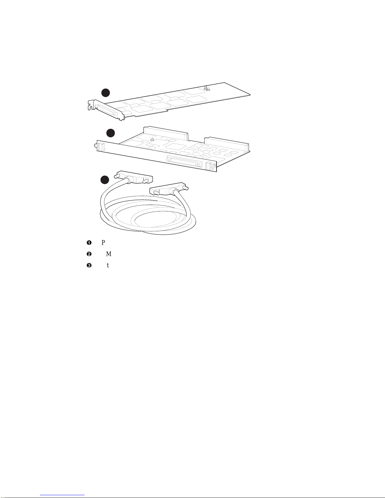
Introduction to the PCI32-VME64 Adapter
1–4 DIGITAL PCI32-VME64 Adapter Hardware Owner's Guide
To illustrate the memory mapping approach, consider each type of transaction that might
occur:
• Direct Memory Access (DMA):
Generally used to achieve the fastest transfer of bulk data, DMA refers to the ability of a
VME module to directly access host memory without involving the host CPU. Two types
of DMA are supported by the PCI32-VME64 adapter:
– Slave-mode – DMA is performed by a processor on a VME device under the direction
of the host CPU.
– Controller (Master) – DMA is performed by the PCI32-VME64 adapter under the
direction of the host CPU.
• Programmed I/O:
Programmed I/O refers to the ability of the CPU to control a data transfer by initiating a
data transfer cycle. It is used for modules that do not support DMA, or when it is not
desirable to permit access by an application program to the memory or registers of a
VME module. Programmed I/0 is required for certain 8-bit and 16-bit data accesses.
• Memory Mapped I/O:
Memory Mapped I/O is used to allow a user level task to access data stored on a VME
module. (The Alpha architecture imposes some restrictions on transactions involving data
transfers shorter than 32 bits.) Memory mapped I/O is supported subject to the technical
limitations and restrictions of the DIGITAL UNIX or OpenVMS Operating Systems.
Refer to the appropriate Software Product Description (SPD) for complete details on
memory mapped I/O support.
Because the PCI32-VME64 adapter is treated like any other processor on the VMEbus, the
PCI32-VME64 adapter can function either as a slave device or as the bus master on the
VMEbus. Consequently, the Alpha host system can directly control and monitor a wide
variety of VMEbus cards and high-performance processors, thus eliminating the need to
purchase an additional VMEbus system controller. As system controller, the PCI32-VME64
adapter will provide 3 levels of arbitration, the VMEbus system clock and system reset, and
the Bus Error global time-out. In addition, interrupts that are generated on the VMEbus by
any VME module can be passed to the host via the PCI32-VME64 adapter. All seven
interrupt levels defined in the VME specification (IEEE 1014C) are supported.
The PCI32-VME64 adapter allows each bus (PCI and VME) to operate independently.
Integrity of the interface between adapter modules is maintained by parity checks on address,
control and data lines.