Figures
2-1
KXJ11-CA
Jumper
Layout. . . . . . . . . . . . . . . . . . . . . . . . . . . . .
..
2-1
2-2
Memory Mapping -PROM in
Low
Melnory. . . . . . . . . . . . . . . . . .
..
2-3
2-3
Memory Mapping -PROM in High Menlory . . . . . . . . . . . . . . . . .
..
2-4
2-4
Boot/Self-Test Switch. . . . . . . . . . . . . . . . . . . . . . . . . . . . . . . .
..
2-5
2-5
Q-
Bus Size Selection . . . . . . . . . . . . . . . . . . . . . . . . . . . . . . . .
..
2-8
2-6
Q-
Bus Base Address Selection . . . . . . . . . . . . . . . . . . . . . . . . . . . . 2-10
2-7
DMA Requests
......................................
2-11
2-8
Locked Instruction Enabie
...............................
2-12
2-9
BREAK Enable
.....................................
2-13
2-10 HALT Option Selection
................................
2-14
2-11 Power-Up Option Selection. . . . . . . . . . . . . . . . . . . . . . . . . . . . . . 2-15
2-12 PROM Addressing
...................................
2-16
2-13 SLU1 Baud Rate
....................................
2-17
2-14 SLU1
Transmitter
...................................
2-19
2-15 SLU1 Receiver
.....................................
2-20
2-16 SLU2 Channel A Receiver
..............................
2-21
2-17 SLU2 Channel B Transmitter
............................
2-23
2-18 SLU2 Channel B Receiver
..............................
2-24·
2-19 Real-Time Clock Interrupt
..............................
2-25
4-1
Backplane Installation . . . . . . . . . . . . . . . . . . . . . . . . . . . . . . .
..
4-1
4-2
Using
Grant
Cards . . . . . . . . . . . . . . . . . . . . . . . . . . . . . . . . .
..
4-2
5-1
Parallel
110
Interface Pin Assignments . . . . . . . . . . . . . . . . . . . . .
..
5-1
5-2
J2
and
J3
Pin Assignments (lO-Pin) . . . . . . . . . . . . . . . . . . . . . . .
..
5-3
5-3
J1
Pin Assignments (40-Pin)
......................
: . . . . .
..
5-3
5-4
Loopback Connectors. . . . . . . . . . . . . . . . . . . . . . . . . . . . . . . .
..
5-8
Tables
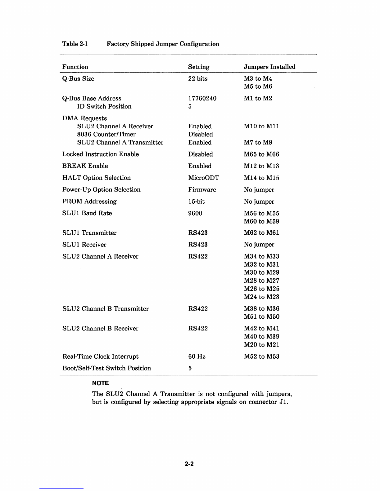
2-1
Factory Shipped
Jumper
Configuration . . . . . . . . . . . . . . . . . . . . .
..
2-2
2-2
Boot/Self-Test Switch Functions . . . . . . . . . . . . . . . . . . . . . . . . .
..
2-5
2-3
Q-Bus Base Address Selection . . . . . . . . . . . . . . . . . . . . . . . . . .
..
2-9
2-4
SLU1 Baud Rate Jumpering
..............................
2-18
4-1
KXJ11-CA Pin
Identification.
. . . . . . . . . . . . . . . . . . . . . . . . . .
..
4-3
5-1
RS422/RS423 Interface to
J1
. . . . . . . . . . . . . . . . . . . . . . . . . . .
..
5-4
5-2
RS232-C Interface to
J1
. . . . . . . . . . . . . . . . . . . . . . . . . . . . . .
..
5-6
5-3
CCITTN.35 Interface to
J1
. . . . . . . . . . . . . . . . . . . . . . . . . . . .
..
5-7
6
..
1 LED Display Definitions. . . . . . . . . . . . . . . . . . . . . . . . . . . . . .
..
6-2
iv