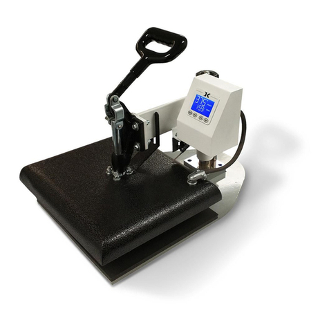
Digital Knight DK20SP User manual

Version 2-12
Digital Knight 16x20
Digital AUTOMATIC Swinger

Contents

Introduction
Congratulations on your purchase of the Air Operated Automatic
DK20SP 16x20 digital swinger! This heat press machine has many ex-
citing features, all of which are meant to help make your heat transfer
pressing endeavors as successful and easy as possible. Please take the
time now to thoroughly read through this manual to become acquaint-
ed with them. It will explain some key features, concepts and methods
that will save much time and effort in using this press and in your heat
pressing applications.
Throughout this manual, many areas and components of this ma-
chine will be referred to by specic names. Please refer to the illustra-
tions below in order to become familiar with some of the terminology
used in this manual.
Temperature
°F/°C Indicator
Ready/Heating Indicator
Open/Timing/Done Ind.
Time
Pressure Bar Graph
TEMP key
PRG key
Up/Down Arrow keys
Default Operating Mode of Controller
Height Knob
Top Head
Power Inlet
E-Stop Button
Activate Button(s)
Heat Platen
Lower Table
Silicone Pad
Pressure Gauge
Air Inlet
Air Regulator

Setup & Suggestions
• Locate the press on a rm, sturdy work surface. It is recommended but
not necessary to bolt the press to a workbench using the rear mounting
holes on the base frame.
• A stand on lockable casters is available from Geo Knight & Co or your
distributor.
• The height of the bench/work space the press is located on would be
ideally 27” to 32” high.
• Attach the power cord from the rear to the underside of the top head.
There is a power inlet under the top head that the modular cord will
plug into.
• It is HIGHLY RECOMMENDED that the cord be strapped or tied to
the back white post of the press, so that the cord is not pulled on and
tugged out of the power inlet where it plugs into the press. TEST and
make sure the cord travels freely when swinging the press, and that
there is no tension or pulling on the inlet socket where the power cord
plugs into the head. Make sure the cord can not be pressed by the
heater.
• The top head should be swung over the pressing table when not in
use.
• The air attachment is a 1/4” or 3/8” female NPT pipe thread. A standard
1/4” or 3/8” threaded male NPT tting can be used. 3/8” or 1/4” ID
hose will provide enough air volume for this press.
• The speed in which the press opens can be adjusted. Underneath the
front skirt of the press, behind the air regulator and air gauge, a brass
ow control can be found. (Slide the press forward off your benchtop to
look underneath.) This is where the air exits the press when the time is
nished and the press releases. If the press is releasing TOO SLOWLY
- the ow control valve can be loosened so that the air releases faster,
and the press opens quicker. If the press is releasing TOO QUICKLY
(slamming/banging down upon completion) the ow control can be
tightened so that the air releases slower, and the bottom table drops
more smoothly. If the air supply is dirty/oily, this may become clogged,
resulting in a slower and slower release. Remove the ow control and
clean it thoroughly.

Normal Operation
Normal Operating Mode
The pressure bar graph is not used on this automatic press.
Setting Temperature

Setting Time
Pre-Press Timer

Setting Platen Height
The height adjustment knob on the DK20SP allows for thicker
items to be placed in the press. The factory set height of the press is
the proper platen height setting for most fabrics, and materials under
1/4” thick. Unlike manual presses, the actual amount of pressure on the
DK20SP is determined by the air regulator and air gauge, NOT by the
height of the heat platen. However, if the platen height does not provide
enough clearance for especially thick items, this can be adjusted. There
should normally be 1/2” to 3/4” gap between the heater and bottom pad
or workpiece.
• To raise the heat platen, turn
the pressure knob to the left,
counterclockwise. The top head will
rise away from the lower table.
• To lower the heat platen, turn
the pressure knob to the right,
clockwise. The top head will lower
toward the pressing table.
Activating the Press
To actuate the machine, simply
press both black buttons together.
This will cause the air bladder to
ll, the table to raise, and the work
to be pressed. The digital timer will
automatically begin cycling. At the
end of the timer cycle the press will
automatically release and the timer
will reset to the preset time. BOTH
black buttons must be pressed together, to insure that both operators hands
are clear of the pressing area, for safety purposes.
To interrupt the timing cycle, in order to do a quick pre-press or
press for a shorter period of time than is set, simply press both black
buttons together again. For emergency one-hand release of the air pres-
sure, press the middle button on the front panel. THE GREEN
LIGHT MUST BE ON IN ORDER TO OPERATE
THE PRESS.

Guidelines & Standard Settings
The following information covers some basic guidelines for press-
ing, as well as some generic parameters for basic heat transfer applica-
tions.
• When pressing shirts, it is often recommended that the shirts be quickly
pressed for 2 to 4 seconds before transferring to remove wrinkles and water
content.
• When pressing two sides of a garment, pull the garment over the table so
that the printed side drapes underneath the table. This will avoid reheating
previously transferred designs on opposite sides of garments. It will also
avoid any bleed-through of inks on lighter fabrics.
• Avoid laying collars, cuffs, zippers, and other bulky parts of garments
on the lower table, as these can adversely affect pressing conditions, and
reduce the life of the silicone pad.
• When pressing rigid substrates (plastics, metals, woods, etc.), be sure that
any protective lms or laminates are removed before heating.
• Always check that the transfer image is face down against the material, to
avoid sealing the image against the heat platen instead of the substrate.
Always follow the transfer media suppliers instructions when
pressing. The information below is for general reference only, and may
not be as accurate as the instructions provided by the transfer media &
imprintable substrate supplier.
• Hot Split Supplier Transfers 350-375°F, 8-10 secs
• Puff Transfers 350-375°, 5-7 secs (extra heavy pressure)
• Ink-Jet Transfer Papers 360°, 15-18 secs
• ColorCopy/Laser Transfer Papers 375°, 20-25 secs
• Sublimation Inks (Polyester Fabrics) 400°, 35 secs
• Sublimation Inks (Plastics) 400°, 1 min, 15 secs
• Sublimation Inks (Metals) 400°, 1 min
• Sublimation Inks (Woods) 400°, 1 min, 15 secs
• Sublimation Inks (Ceramics) 400°, 4 min

ERR Mode
Over-Temp Alarm

Loading a Preset
Programmable Presets
How Presets Work

Editing/Programming a Preset

A Walkthrough Tutorial for using Presets
Part 1:
Part 2:

User Menus
Entering the user menus & options
To access the user menus, simply press TEMP & PRG at the same
time from the normal operating mode and let go.
(Try to use two hands and press the keys at the exact same time. If one
key is pressed too early from the other, the temperature setting or preset
modes may be activated instead. Turn the press off and then on and try
again.)
Fahrenheit / Celsius
Timer Counter Units

Recorded Pressings (User Odometer)
Pressure Minimum
Pressure Maximum

Temperature Drop Sense
Keypad Beeper

Alarms
• denotes a short beep.
_ denotes a longer beep.
~ denotes innite loop.
Alarm # Alarm Pattern
Off No alarm
01 • • • _
02 • • • _ ~
03 • • _
04 • • _ ~
05 • • •
06 • • • ~
07 _ ~
08 _
09 •
10 • (shorter)

Finished Warning Beep
Prepress Timer

Prepress Alarms
• denotes a short beep.
_ denotes a longer beep.
~ denotes innite loop.
Alarm # Alarm Pattern
Off No alarm
01 • • • _
02 • • • _ ~
03 • • _
04 • • _ ~
05 • • •
06 • • • ~
07 _ ~
08 _
09 •
10 • (shorter)
Operator Lockout

Maintenance
• The Lifter Springs & Shoulder Bolts are the greatest area of wear and
friction on the press. However they rarely if at all need to be replaced. If
the press raises and lowers unevenly, carefully turn the press on its side
and inspect the 4 springs. Replace all 4 springs at the same time if one or
more are broken or not even.
• Lightly Lubricating the lifter springs with white lithium grease or similar
spray on lubricate will greatly reduce squeaking and noise from the
underside of the press
• The air regulator is the easiest component to clog and damage from
contaminated air. Make sure a water trap / lter is placed inline with the
air supply before the connection to the press. The cleaner and drier the air,
the longer the life of the air regulator and other pneumatic components.
• The black push-buttons and rear safety switch should last many tens of
thousands of pressings. If however activation of the press is sporadic,
replace the push buttons and rear safety switch.
• The silicone pad on the lower table can degrade after much use and over
an extended period of time. This pad is replaceable. If the pad becomes
dried out, cracked, or there are chunks removed from the silicone pad, this
can result in inconsistent and poor quality transfers.
Parts / Maintenance / Misc

Replacement Parts
DKP-ACTCVR ................DK20SP FRONT COVER W/SWITCHES/ASBLY
SHN-DKPHOOD .............DK20SP FRONT COVER PANEL ONLY
ELN-ABB1 ......................PUSH BUTTON PANEL MOUNT (BLACK)
ELN-110SP ......................SPST PUSH/ ON-OFF SWITCH (E-STOP)
ELN-8043X1 ....................PILOT LIGHT (GREEN) 120V SOLICO
ARN-AR20HZ .................¼ NPT SMC REGULATOR W/PANEL NUT
ARN-15UB8 ....................PANEL MOUNT 0-160 AIR GAUGE 1½ DIA
SHN-DKPSKT .................DK20SP BOTTOM PANEL SKIRT
DKP-PVSWBX................DK20SP REAR PIVOT SWITCH BOX
DKP-HDHNDL ...............DK20SP HANDLE BAR W/KNOB
ARN-7564 ........................STYLE 116 MEDIUM AIR BAG
ARN-35AAA120V ..........MINI-3 WAY MAC VALVE 120V 35A SERIES
ARN-4ZJ85 ......................¼” EXHAUST PORT FLOW CONTROL
MEN-M5 ..........................3/4 X 3/8 X 3” DIE SPRING
FAS-AB383 ......................3/8 X 3 SOCKET HD SHOULDER SCREW
DKA-CTRLC ...................DIGITAL KNIGHT PROCESSOR BOARD
DKA-CTRLP ...................DIGITAL KNIGHT POWER BOARD
ELN-KM0227A1 .............DIGITAL KNIGHT MEMBRANE KEYPAD
RPK-DKPWR ..................DK POWER INLET/SWITCH/CORD KIT
DK2S-HBA120 ................DK20S/SP 16X20 HEATER BLOCK ASBLY
CAN-DKKNOB ...............DK/DC BLACK KNOB
FAS-EM5818 ...................5/8-18 HEX ACORN NUT
MEN-DKPVBLT .............DK/DC PIVOT BOLT
FAS-NTA1018 .................THRUST BEARING (2 req)
MEN-TWB1018 ..............SMALL WASHER THRUST BEARING (4 req)
SRM-381620 ....................3/8 X 16 X 20 SILICON SPONGE
MEN-DKCLLR ...............DK20S/SP STOP COLLAR
SHN-DK2SCVR ..............DK20S/SP TOP CONTROL PANEL COVER
SHN-DK20SHBC ............DK20S/SP 16X20 HEATER BLOCK COVER
ELN-K26TC ....................K-26” THERMOCOUPLE
ELN-MSTB2.5.................OST 5MM TRMNL THERMOCOUPLE PLUG
Table of contents
Other Digital Knight Power Tools manuals
