SSM 2 pro User manual

INSTRUCTION MANUAL
WARNING!
TO REDUCE THE RISK OF INJURY, USER MUST READ
AND
UNDERSTAND THIS INSTRUCTION MANUAL.
ORIGINAL
INSTRUCTIONS
Date
of
purchase: ....................................
SSM-2 PRO manual.en ©
05/2015
SSM
ProduktAB

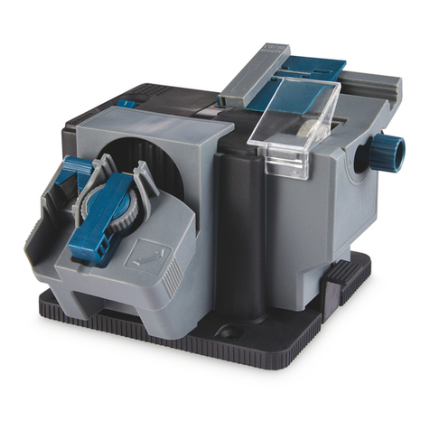
SSM-2 PRO skate
sharpening
machine
Congratulations
on
your
purchase
of
a SSM-2
PRO
skate
sharpening
machine.
We
sincerely
thank
you
for
selecting
a
product
from
SSM
Produkt
AB.
To
obtain
an
additional
copy
of
this
manual, please
contact
SSM
at:
TABLE
OF
CONTENTS
SSM
PRODUKT
AB
Vaksala-Eke
SE-755 94 Uppsala, Sweden
Tel: +46 (0)18 500840
E-mail: [email protected]
Internet:
www.ssmprodukt.com
Limited Warranty.......................................................................
...
...............
..
..
...............
..
...........2
General Safety Rules.....
....
...............
..
...............
..
..
...............
..
.................
..
.................
..
............3-4
Specific Safety Rules and Symbols.......
..
...............
...
.................................................................5
Functional Description.
..
.................
..
...............
..
..
...............
..
...............
....
...............
..
.................6-7
Assembly
...
...................
...
...............
..
..
...............
..
...............
...
................
...
.................................. 8
Operation.........
..
...............
....
...............
..
.................
..
.................
..
.................
..
...............
....
......
9-11
Maintenance..................................
...
...............
..
..
...............
..
...............
...
.................................12-13
Technical Specifications and Dimensions.....
..
.................
..
.................
..
.................
..
...............
..
.13
Accessories................................................................
...
...............
..
...............
..
..
...............
...
....14-15
LIMITED WARRANTY
Scope
of
warranty
This warranty covers any defects
in
materials and workmanship under normal use.
Period
of
coverage
This warranty runs for two (2) years from the date
of
purchase. Please save your receipt or invoice.
Limitations
Failures due to abuse, misuse or
an
event or effect that cannot
be
reasonably anticipated or controlled (such as
flood, earthquake, act
of
God etc.) are not covered by this warranty. Surface coating problems caused by excessive
humidity, in-use scratches or abrasions, and direct exposure to the elements are also not covered.
Repair or replacement is the only option available under this warranty. SSM Produkt
AB
(SSM)
is
not responsible
for damages
of
any kind, including incidental and consequential damages.
Incidental damages include but are not limited to such damages as loss of time and loss of use. Consequential
damages include but are not limited to the cost
of
repairing or replacing property that was damaged ifthe product
from SSM does not work properly.
Correction
of
details
If your product cannot
be
repaired, we will replace your product free of charge.
How
to
get
service
Please return the defective product together with the purchase receipt or the invoice.
You
can obtain service by
contacting a dealer of SSM products or SSM directly. At our discretion, the dealer or SSM will either repair or replace
your product.
How
country
and state laws relates
to
the
warranty
This warranty gives you specific legal rights.
You
may also have other rights that vary from country to country and
from state to state.
SSM
PRODUKT
AB
RESERVES THE RIGHT TO
MAKE
IMPROVEMENTS
AND
MODIFICATIONS TO DESIGN
WITHOUT
PRIOR NOTICE.
SSM
PRODUKT
AB
VAKSALA-EKE,
SE-75594,
UPPSALA,
SWEDEN

GENERAL SAFETY RULES
IAI
WARNING!
When using electric tools basic safety precautions should always
be
followed to
reduce the risk of fire, electric shock and personal injury including the following.
Read all these instructions before attempting to operate this product and save these instructions.
Safe Operation
Keep your work area clear.
-Cluttered areas and benches invite injuries.
Consider work area environment.
-
Do
not expose tools to rain.
-
Do
not use tools
in
damp or wet locations.
-Keep work area well lit.
-
Do
not use tools
in
the presence
of
flammable liquids or gases.
Guard against electric shock.
-Avoid body contact with earthed or grounded surfaces (i.e. pipes, radiators, ranges, refrigerators).
Keep otherpersons away.
-
Do
not let persons, especially children, not involved
in
the work touch the tool or the extension cord and keep them
away from the work area.
Store idle tools.
-When not
in
use, tools should be stored
in
a dry locked-up place, out
of
reach
of
children.
00
not force the tool.
-It will do the job better and safer at the rate for which it was intended.
Use the right tool.
-
Do
not force small tools to do the job of a heavy duty tool.
-
Do
not use tools for purposes not intended; for example do not use circular saws to cut tree limbs or logs.
Dress properly.
-
Do
not wear loose clothing or jewelry; they can be caught
in
moving parts.
-Non-skid footwear
is
recommended when working outdoors.
-Wear protective hair covering to contain long hair.
Use protective equipment.
-Use safety glasses and hearing protection.
-Use face or dust mask ifworking operations create dust.
Connect dust extraction equipment.
-If the tool
is
provided for the connection of dust extraction and collecting equipment, ensure these are connected and
properly used.
00
not abuse the cord.
-Never yank the cord to disconnect
it
from the socket. Keep the cord away from heat, oil and sharp edges.
Secure work.
-Where possible use clamps or a vice to hold the work. It
is
safer than using your hand.
00
not overreach.
-Keep proper footing and balance at all times.

GENERAL SAFETY RULES (continued)
Maintain tools with care.
-Keep cutting tools sharp and clean for better and safer performance.
-Follow instruction for lubricating and changing accessories.
-Inspect tool cords periodically and ifdamaged have them repaired by
an
authorized service facility.
-Inspect extension cords periodically and replace if damaged.
-Keep handles dry, clean and free from oil and grease.
Disconnect tools.
-When not
in
use, before servicing and when changing accessories such as blades, bits and cutters, disconnect tools
from the power supply.
Remove adjusting keys and wrenches.
-Form the habit of checking to see that keys and adjusting wrenches are removed from the tool before turning
it
on.
Avoid unintentional starting.
-Ensure switch
is
in
"off' position when plugging
in
.
Use outdoor extension leads.
-When the tool
is
used outdoors, use only extension cords intended for outdoor use and so marked.
Stay alert.
-Watch what you are doing, use common sense and do not operate the tool when you are tired.
Check damaged parts.
-Before further use of tool,
it
should be carefully checked to determine that it will operate properly and perform its
intended function.
-Check for alignment of moving parts, binding of moving parts, breakage
of
parts, mounting and any other conditions
that may affect its operation.
- A guard or other part that
is
damaged should
be
properly repaired or replaced by
an
authorized service center unless
otherwise indicated
in
this instruction manual.
-Have defective switches replaced by
an
authorized service center.
-Do not use the tool ifthe switch does not turn it
on
and off.
Warning.
-The use
of
any accessory or attachment or performance of any operation with this tool other than those recommended
in
this instruction manual may present a risk
of
personal injury.
Have your tool repaired
by
a qualified person.
-This electric tool complies with the relevant safety rules. Repairs should only be carried out by qualified persons using
original spare parts; otherwise this may result
in
considerable danger to the user.
Noise
-The typical A-weighted noise levels determined according to
EN
61029-1 :2009 :
Sound pressure level
(L
pA
) : 80 dB
Sound power level
(L
WA
):
93 dB
Uncertainty (K): 2,5 dB
EC-DECLARATION OF CONFORMITY
We, SSM PRODUKT AB, Vaksala-Eke, SE-755
94
, Uppsala, Sweden declare that the product SSM-2 to which this
declaration relates
is
in
conformity with the following standards:
EN
61029-1 :2009
EN
55014-1 :2006
EN
61000-3-2:2006
EN
61000-3-3:2008
EN
55014-2:1997+A1:2001+A2:2008 Uppsala, November
21,2014
Stefan Gustavsson
(place, date) (signature, name)
following the provisions of 2004/1 08/EC, 2006/42/EC and 2006/95/EC directives.

SPECIFIC SAFETY RULES AND SYMBOLS
WARNING! READ OPERATOR'S
MANUAL BEFORE USING
THE MACHINE
The machine must be used only for the purpose
of
grinding skate blades.
EYE AND HEARING
PROTECTION REQUIRED
Always fasten the skate in the skate holder. NEVER hold skate being sharpened only by your hands.
It
is important
to
support the work properly
to
get the best result possible, minimize body exposure and loss
of
control.
Check grinding wheel protective cover for proper fit before using the machine to minimize the risk
of
flying debris.
Keep hands and body away from the rotating grinding wheel.
Contact with a rotating grinding wheel
or
parts from an exploding grinding wheel can result
in
serious injury.
Only use grinding wheels approved by SSM Produkt AB. Use grinding wheels with correct size and shape.
Unauthorized grinding wheels may be dangerous!
Keep grinding wheel securely fastened.
When fastening grinding wheel, never use damaged or incorrect flange, flange washer or nut.
The flange and flange washer were specially designed for the machine, for optimum performance and safety
of
operation.
Safety Warnings Specific for Grinding:
Use only wheel types that are recommended for your power tool and the specific guard designed for the
selected wheel. Wheels for which the power tool was not designed cannot be adequatelyguarded and are unsafe.
The guard must be securely attached to the power tool and positioned for maximum safety, so the least amount
of
wheel is exposed towards the operator.
The guard helps
to
protect operator from broken wheel fragments and accidental contact with wheel.
Wheels must be used only for recommended applications. For example: do not grind with the side
of
cut-off
wheel. Abrasive cut-offwheels are intended for peripheral grinding, side forces applied
to
these wheels may cause
them
to
shatter.
Always use undamaged wheel flanges that are
of
correct size and shape for your selected wheel.
Proper wheel flanges support the wheel thus reducing the possibility
of
wheel breakage. Flanges for cut-offwheels
may be different from grinding wheel flanges.
Do not use worn down wheels from larger power tools.
Wheel intended for larger power tool
is
not suitable for the higherspeed
of
a smaller tool and may burst.

FUNCTIONAL DESCRIPTION
1.
Hole
for
fastening
the
machine
2a. Guide arm
2b. Where
to
put
the
skate
holder
3.
Extractor
tube
4a. Blade
support
device
4b. Scale wheel
for
adjusting
roller
5.
Power
switch
6.
Grinding
wheel
7.
Protective
cover
8a.
Pivot
device
8b. Diamond
for
hollow
shape
8c. Ruler
8d.
Adjusting
screw
9a. Flat
surface
device
9b. Diamond
for
plane shape

FUNCTIONAL DESCRIPTION (continued)
The machine
is
intended to do the finishing sharpening
on
skate blades (flat or hollow).
This
is
done by manually moving the skate blade (mounted
in
a holder) against a suitably dressed, rotating grinding
wheel. The open construction of the machine allows for a constant and easy supervision of the sharpening process.
The machine
is
built around a modified electric grinding machine with a guide arm attached to
it.
The electric motor
is
attached to a bottom plate. It
is
intended that the bottom plate should
be
kept horizontal. The axle of the electric
mo
tor will then
be
vertical.
On
the axle the following items are mounted
in
this order: a flange, a grinding wheel,
a flange washer, a balancing ring and a fastening nut. This
is
all partially covered by a protective cover.
1.
The Hole
for
fastening the machine can be used to attach the machine to the surface where it's placed.
Use a screw to attach it if necessary.
2a. The Guide arm
is
a flexible, horizontal arm which directs the skate holder.
2b.
You
put a skate holder
in
the plastic bushing
on
the front arm. Fasten your skate
in
that skate holder.
3.
The Extractor tube
is
intended to collect sparks and other debris created when grinding and dressing.
Fasten
it
onto the bottom plate with the wing nut
in
the angle you prefer; then attach a suitable dust extracto
r.
4a. The Blade support device
is
used to get the hollowness
on
your skate centered by controlling the vertical position
of the skate holder. When sharpening a skate hollow, put the skate blade
on
top
of
the roller.
4b. The Scale wheel ranges from 2.5 to 4.2
mm;
turn it to the skate blade thickness to get hollowness exactly centered.
5.
The Power switch
is
used to turn the machine
on
and off.
6.
The Grinding wheel rotates counter clockwise and
is
used to sharpen the skate blade.
Use grinding wheel S-2/HP70, S-2/ME60,
S-2/KBSO,
S-2/KB60 or S-2/60.
7.
The Protective cover
is
a guard that protects if a grinding wheel would break. It also prevents sparks from
spreading. The protective cover
is
fastened by three top nuts.
Sa.
The Pivot device
is
used with a diamond to dress the grinding wheel for hollow sharpening.
Use the nut to fasten the diamond.
Sb.
Use diamond
O-SO
or
SO-SO
.
Sc.
The Ruler (scale
in
mm/inch.)
is
used when measuring
on
the pivot device. Measure from the head of the
diamond to the pivot; the distance gives the hollowness obtained
on
your skate. See "AOJUSTMENTS".
Sd.
The Adjusting screw
is
used to move the pivot device inwards or outwards.
This
is
done by screwing
it
clockwise (outwards) or counter clockwise (inwards).
Scale 2
:1
GRINDING
WHEEL)
L-
__
-.--
__
--'
Dressed
by
pivot device.
Scale
1:1
Hollowness 13 mm
(Oeep Hollowness)
Skate
Blade
Hollowness
20
mm
(Shallow Hollowness)
9a. The Flat surface device
is
used with a diamond to dress the grinding wheel for flat sharpening.
9b. Use diamond SO-50,
SO-SO
or
O-SO.
Scale 2
:1
GRINOING WHEEL
Dressed
by
flat surface device.

ASSEMBLY
Your skate sharpening machine SSM-2 PRO
is
delivered complete (and the skate holder that you
ordered with the machine) and protected inside its delivery box. Remove all contents from the box
and inspect to ensure no damage was incurred during shipping.
Your SSM-2 PRO package should also include the following:
DESCRIPTION PART #QTY
Instruction manual
Exhaust tube
Allen screw driver
Allen screw driver
Double ended wrench
Skate holder
Getting
started:
SSM-2 PRO manual.en
UT
AS
2.5
mm
AS4mm
DEW 8,10
mm
H-5, H-8, H-10, H-10 S or H-10 P
I
A.
ICAUTION!
(the one you ordered)
IF
POSSIBLE, ALWAYS DISCONNECT THE SKATE SHARPENING
MACHINE FROM THE POWER SOURCE BEFORE MAKING ADJUSTMENTS.
Place the machine on a stable, level surface.
You
can fasten the machine with a screw through the hole (1)
in
the bottom plate.
The machine comes with a grinding wheel mounted and balanced.
Refer to MAINTENANCE:
HOW
TO CHANGE AND BALANCE THE GRINDING WHEEL (on page
12)
if
you want to replace or balance the grinding wheel.
The grinding wheel and the diamond are adjusted for a hollow radius
of
20 mm when delivered
from SSM Produkt AB. Refer to OPERATION:ADJUSTMENTS (on page 9) when you want to
change the radius.
MAKE SURE THAT NO DIAMOND IS TOUCHING THE GRINDING WHEEL WHEN YOU START
THE MACHINE. If necessary, reposition the diamonds outwards. For diamond (9b),screw it
directly. For diamond (8b), screw on the adjusting screw (8d).
MAKE SURE THAT THE BLADE SUPPORT DEVICE
IS
NOT TOUCHING THE GRINDING
WHEEL WHEN YOU START THE MACHINE. Follow the instructions under OPERATION:
ADJUSTMENTS (on page 9) to reposition the blade support device if necessary.
Mount the extractor tube (3) and attach a proper dust extractor. This will reduce the amount
of
sparks and debris. For more complete protection, wear a suitable face mask covering mouth and
nose.
Make sure you wear protection glasses and hearing protection when you use the machine.

OPERATION
ADJUSTMENTS before sharpening
Balancing grinding wheel
If necessary, exchange the grinding wheel.
Balance
it
if needed. (See MAINTENANCE: HOW TO
CHANGE AND BALANCE THE GRINDING WHEEL.)
Adjusting location of the blade support device
If necessary, adjust the position of the blade support
device (4a). It should
be
as close to the grinding
wheel as possible without touching
it.
Therefore, as the grinding wheel gets smaller with
time after repeated dressing (or gets bigger through
exchange to a new wheel) you have to reposition
the roller.
To
do this, first loosen the nut
(M)
on
the
right side
of
the roller's holder. (Avoid the nut
on
the
left side.)
You
can now move the roller's holder by
pushing or gently tapping
on
it.
When
in
a good
position, fasten the nut again. (Make sure that the
roller doesn't touch the grinding wheel.)
Adjusting the height
of
the blade support device
When sharpening hollow, you must make sure that the hollowness will
be
centered
in
the skate blade.
An
adjustment
will
be
necessary if the thickness
of
the skate blade has changed. Turn the scale wheel (4b) to the same number as
your skate blade thickness (4b shows a setting
of
2.B
mm).
Dressing the grinding wheel
To
dress for hollowness, use diamond
(Bb)
in
the pivot device
(Ba)
.
You
adjust the hollowness by screwing the
diamond
in
or out until you reach the correct position.
You
use the ruler
(Be)
to measure from inside the head of the
diamond screw (must
be
a
0-80
or a SD-80) to the pivot device (see Fig.A). The usable limits are 8 to
38
mm.
Secure the diamond
in
place by tightening the nut
on
the diamond screw.
As you dress the grinding wheel, it
is
consumed and gets smaller. Use the adjusting screw
(Bd)
to move the whole
assembly with the pivot device. Move
in
small amounts, at the same time turning the pivot device
up
and down until a
few times when dressing occurs. The dressing should
be
performed gently, so as not to damage diamond or grinding
wheel.
To
dress flat, use diamond (9b). Screw the diamond inwards
in
small amounts, at the same time turning the flat
surface device (9a), so that its diamond moves
up
and down past the grinding wheel. The last few movements should
give dressing. Dress gently.
Here the hollowness
is
set
at
25
mm.

OPERATION (continued)
HOW TO CHECK
IF
THE HOLLOWNESS
IS
CENTERED
It
is
important that you get the hollowness centered
on
the blade. With the SRK PRO blade support device the
hollowness will always
be
centered if you turn it to the same number
as
the skate blade width.
However, if something would malfunction you can check the centering by dressing the grinding wheel
properly, then put the skate
in
the holder with e.g. the front part to the left. Move the blade a few times forwards and
backwards
in
contact with the rotating grinding wheel. Remove the skate and put
it
back
in
the holder with the front
part to the right (the blade
is
now upside down). Slightly let the blade touch the grinding wheel to get a small
grinding mark (witness mark). If the mark fits into the hollow
(mark
C), then the SRK PRO
is
correctly adjusted. If the
mark covers the lower part
of
the blade
(mark
L1
or
L2), the supporting roller
is
too high. If the mark covers the upper
part
(mark
R1
or
R2) the supporting roller is too
low.
If SRK PRO needs
to
be
adjusted, check the separate SRK PRO
instruction paper how its done.
Another easy way of checking if the sharpening
is
centered
is
to
use the BEC, Blade Edge
Checker
(check the
separate BEC instruction paper how its done).
HOW TO ADJUST THE FLAT SURFACE DEVICE
The flat surface device comes with correct
setting from the factory. If necessary,
it
can
be
adjusted by loosening the lock screw and
correcting the angle using the adjustment
screw.
You obtain the correct angle as follows:
Dress the grinding wheel. Sharpen a skate,
then turn
it
in
the holder and let the blade
touch the grinding wheel to make a small
witness mark.
Compare to HOW TO CHECK
IF
THE
HOLLOWNESS
IS
CENTERED above.
If
you
get a mark that
is
not perfect, then
the angle
is
wrong. Adjust and try again.
(You
can also use the BEC here for
checking if the angle is correct.)

OPERATION (continued)
SHARPENING THE SKATE (advice)
Dress grinding wheel
Connect the machine to the power source and start it (using the powerswitch 5). Use the diamond (8b or 9b) to dress
the grinding wheel
so
that it will give the desired shape to the blade (flat or with desired hollowness).
If the grinding wheel feels blunt, you should dress it even if the shape does not have
to
be changed.
Hollow sharpening: Ice hockey skates and Figure skates
Correct any damage
on
the skate blade
Check the skate blade for damage. If massive damage is found,
use a whetstone to get the blade even
on
the sides.
Then fasten the skate
in
the skate holder.
Sharpen it at least twice with constant pressure applied
against the grinding wheel, see figure: p
When sharpening, keep the skate blade directed along a
straight line (PQ
in
the figure). Move the blade forwards and
backwards
in
the same direction as the arrows indicate.
Flat sharpening: Bandy skates and Touring skates
x
The two "X" points
in
the figure marks where the blade starts
to
turn away from the
Q
grinding wheel. Start the sharpening movement
"in
the air" outside an X-point. Then make a smooth contact with the
grinding wheel.
At
the otherX-point the skate will turn away from the grinding wheel. Continue the movement a bit
without having contact with the grinding wheel but the skate blade still on the support roller, before turning back and
doing the movement
in
the otherdirection.
Check for any remaining damage. If damage is found, repeat the sharpening until all damage or wear is gone.
Final sharpening
When no damage remains
on
the skate blade, sharpen the whole blade including the round ends slowly and smoothly.
Use light pressure to get a better micro finish and to avoid removing too much material from the round edges. Perform
the movement as shown below
in
one continuous sequence A+B+C or C+B+A. Remember to keep the B movement
straight.
A
Finish
Use a flat whetstone approximately twice
on
each side of the blade to remove any abrasive wounds.
ATTENTION!
When sharpening hollow, make sure that the skate blade always has contact with the blade support roller (4a).
00
not move the skate too slowly against the grinding wheel and do not apply too much pressure against
it.
The
skate blade may be "burnt" because too much heat
is
generated locally!
When sharpening, keep your hands on the skate and not on the skate holder.
00
not let the skate carry too
much weight
of
yourhands. Otherwise the skate blade will tilt from the horizontal plane.

MAINTENANCE
HOW TO CHANGE AND BALANCE THE GRINDING WHEEL
A
1 4 1. Grinding wheel
2. Flange washer
2 3. Balancing ring (eccentric ring)
4. Mark point on balancing ring
5. Nut
3 5
B C D E
1. First test the grinding wheel for cracks. Hold the wheel
on
a finger (through the center hole) and gently tap
on
it.
By listening
to
the sound you can check whether the wheel contains cracks.
Remove the protective cover, the nut, the balancing ring , the flange washer and the
old
grinding wheel.
(To
avoid wobbling of the grinding wheel, remember to thoroughly clean flange, flange washer and grinding wheel
mounting surface before mounting.)
Then put the new grinding wheel
on
top of the flange. Put the flange washer and then the balancing ring
on
top
(in
the neutral position, i.e. centered with the mark point
in
the
12
o'clock direction).
Fasten the nut with the grinding wheel having some selected mark (selected by you)
in
the 12 o'clock direction.
Start the engine and dress the grinding wheel with one of the diamonds.
Don't forget to have the protective cover on! If the grinding wheel vibrates, adjust using the following scheme.
(The grinding wheel will impart vibrations to the whole machine. They are most easily felt at the end of the guide
arm at the skate holder.)
2. Stop the engine and direct the grinding wheel
in
the 12 o'clock direction. Loosen the nut and move the balancing
ring somewhat
in
the 6 o'clock direction (i.e.
an
eccentric position).
Fasten the nut and restart the engine. Remember how much the grinding wheel vibrates (Fig.
B).
3. Do as
in
step 2, but with the mark point
in
the 9 o'clock, 6 o'clock and 3 o'clock directions.
The amount of eccentricity of the balancing ring should
be
kept the same (Figs.
C,
0, E).
4.
If there are fewer vibrations
in
some direction, turn the balancing ring
so
that its mark point has that direction.
If two directions give fewer vibrations than the others, put the mark point direction between the two.
Then fasten the grinding wheel with the balancing ring adjusted. Start the engine and dress the grinding wheel.
If the grinding wheel still vibrates, make a precision adjustment.
5.
If a precision adjustment
is
needed, move the balancing ring
in
small amounts to be more centered or more
eccentric or change the direction of its mark point slightly. Start the engine, dress the grinding wheel and test
if the vibrations lessen. This
is
an
iterative procedure.
It
should
be
possible to adjust until the vibrations practically disappear.

MAINTENANCE (continued)
SERVICE
If the machine is used correctly and only for sharpening skates then service is seldom needed. However, the grinding
wheel and diamonds should regularly be replaced. The grinding wheel should be replaced when the distance between
its outer diameter and the front edge of the protective cover has decreased to approximately 10 mm. (When the
diameter
of
the grinding wheel goes below 120 mm, the grinding wheel should be replaced
to
give a good result.)
To
retain the capacity of the machine and to continue to get a good result, always keep the machine clean.
Clean the outside. Remove dust with a soft brush if needed.
WARNING! A complete service should always be performed by a qualified technician. When performing maintenance
yourself (e.g. replacing grinding wheel or diamonds) ensure that the electric plug is disconnected.
To
avoid danger,
work
on
electrical parts should always be done by a qualified technician.
For power tools with type Y attachment: if the replacement of the supply cord is necessary, this has
to
be done by the
manufacturer or his agent
in
order
to
avoid a safety hazard.
TECHNICAL SPECIFICATIONS AND DIMENSIONS
HEIGHT (without holder and extractor tube): 320
mm
WIDTH (without holder and extractor tube): 250
mm
LENGTH (without holder and extractor tube): 350
mm
WEIGHT (without holder and extractor tube): 14.8
kg
POWER:
250W
VOLTAGE: 220-240 V
FREQUENCY: a.c. (1-phase) 50-60 Hz
MAXIMUM RPM: 2800-3400 RPM
GRINDING WHEEL TYPE:
GRINDING WHEEL DIMENSIONS:
(Diameter * Thickness * Arbor)
DIAMOND:
Type 5-2 from SSM
150 * 6 * 38
mm
For flat sharpening: SO-50,
50-80
or 0-80
For hollow sharpening:
50-80
or 0-80
THE MACHINE
IS
INTENDED FOR INTERMITTENT USAGE (on 60s I off 60s).
It
is
also available
in
a
c
~u
s
approved
110-120 V version.
Intertek
Your SSM Produkt AB distributor:

ACCESSORIES
--------------------------------------- G
RI
N
DIN
G WHEELS ---------------------------------------
5-2/60
Pink
Grit size 60
Standard wheel
S-2/HP70
Yellow
Grit size 70: special
For professional teams
S-2/ME60
Pink/purple
Grit size 60: ceramic
Excellent
on
all steels
S-2/KSO
Light blue
Grit size 80: ceramic
For professional teams
-------------------------------------- DIAMOND DRESSE
RS
--------------------------------------
o-SO
Natural diamond
For:
Pivot device &
Flat surface device
so-so
Synthetic diamond
For:
Pivot device &
Flat surface device
SO-50
Synthetic diamond
For:
Flat surface device
------------------------------ WHETSTONES OR HAND HONES ------------------------------
B-SSM
From silicon carbide
One fine grit size
Size: 75x18x10 mm
BB-SSM
From silicon carbide
Same mixture as 8-SSM
Size: 75x25x10 mm
CB-SSM
From aluminum oxide
Two different grit sizes
Size: 75x18x10 mm
OB-SSM
Diamond hand hone
Precision tool
Handle with care!
Size: 75x25x5.5 mm
---------------------------------------
E>CHAlJST
S~STEMS
---------------------------------------
U-S40
Welding fume exhaust
Very high quality
_
®®
til,
Uses the U-324 filter
(
14
))
~
NQS500
Dust extractor
Very powerful and quiet motor
Uses a cyclone intake

ACCESSORIES
---------------------------------------------
E:CllJIJlnnE:~lr
---------------------------------------------
V-2
Transport case for SSM-2
Size: 420x330x360 mm
Very durable to thrusts
BEC
Blade Edge Checker:
Controls that a sharpening is
centered
on
the skate blade.
SKR
Blade Straightener:
Used to straighten a
bent skate blade.
-----------------------------------------
~~lrE:
~()L.[)E:Ft~
-----------------------------------------
H-5
Original skate holder
For:
Ice hockey and Bandy
(not small childrens skates)
Universal s
For:
All skates (except some figure
skates and large goalie skates)
H-7
Goalie skate holder
For:
All goalie skates
Figure skates and special ones
like Matrix and Paramount)
H-8
Universal skate holder
For:
All skates (except some figure
skates and
tour
skates)
H-10 P
Figure skate h
For:
Figure skates and special ones
like revolution, parabolic, tapered
,
®S}ill
,
(
15
))
~
