Digital Matter Telematics Remora User manual
Remora User Manual
Revision 1.0 - 9 December 2015
REMORA-UM All information provided in this document is subject to legal disclaimers © Digital Matter 2015
Remora User Manual Revision 1.0 - 9 December 2015 Page 1 of 33
BATTERY POWERED GPS TRACKER
For the latest version of this document, pricing and other product information please contact your
local Digital Matter office.

Digital Matter Remora User Manual
REMORA-UM All information provided in this document is subject to legal disclaimers © Digital Matter 2015
Remora User Manual Revision 1.0 - 9 December 2015 Page 2 of 33
1. TABLE OF CONTENTS
Click on the contents to jump to that location in the document:
1. TABLE OF CONTENTS 2
2. INTRODUCTION 5
2.1 BACKGROUND 5
2.2 TECHNICAL SPECIFICATIONS 5
3. PRECAUTIONS 6
3.1 IP67 RATING 6
3.2 STATIC DAMAGE 6
3.3 BATTERY PRECAUTIONS 6
4. CLOUD INFRASTRUCTURE 7
4.1 OEMSERVER 7
4.2 SOFTWARE PLATFORM FRONT ENDS 7
4.3 ASSISTNOW OFFLINE 8
5. INSTALLATION 9
5.1 SIM INSTALLATION 9
5.2 HOUSING ASSEMBLY 9
5.3 OEM SERVER 9
5.4 DEVICE INSTALLATION 10
6. MAINTENANCE 11
6.1 BATTERY MAINTENANCE 11
6.2 SEAL MAINTENANCE 11
7. DEVICE SETUP 12
7.1 PARAMETER SETUP ON OEM SERVER 12
7.2 DEVICE STATE CHANGES ON OEM SERVER 12
7.3 SETUP BY SMS 12
8. CONNECTIVITY SETTINGS 14
8.1 AUTO-APN 14
8.2 MULTI-APN 16
8.3 ADMIN PARAMETERS 17
9. TRACKING SETTINGS 18
9.1 OVERVIEW 18
9.2 BASIC TRACKING 18
9.3 ADVANCED TRACKING 19
9.4 ACCELEROMETER WAKEUP 20
9.5 MOVEMENT TRIPS 21
9.6 BATTERY VOLTAGE 22
9.7 GPS SETTINGS 23
10. ANALOG AND DIGITAL INPUTS 24
10.1 ANALOG INPUTS 24
10.2 BATTERY LIFE STATISTICS 24
10.3 DIGITAL INPUTS 25
10.4 DIGITAL STATUS FLAGS 25
11.RECOVERY MODE 26
12. BATTERY LIFE PREDICTION 27
12.1 MODELLING THE BATTERY LIFE 27
12.2 EXAMPLES 28

Digital Matter Remora User Manual
REMORA-UM All information provided in this document is subject to legal disclaimers © Digital Matter 2015
Remora User Manual Revision 1.0 - 9 December 2015 Page 3 of 33
13. TROUBLESHOOTING 31
13.1 NO CONNECTION ON BATTERY INSERTION 31
13.2 MISSING UPDATES IN THE FIELD 31
13.3 FORCING A CONNECTION 31
13.4 SHORT BATTERY LIFE 31
13.5 POOR TRIP START PERFORMANCE 33

Digital Matter Remora User Manual
REMORA-UM All information provided in this document is subject to legal disclaimers © Digital Matter 2015
Remora User Manual Revision 1.0 - 9 December 2015 Page 4 of 33
Revision History
Rev
Date
Description
1.0
17 Nov. 2015
First revision

Remora User Manual
Chapter 2: Introduction
Revision 1.0 - 9 December 2015
REMORA-UM All information provided in this document is subject to legal disclaimers © Digital Matter 2015
Remora User Manual Revision 1.0 - 9 December 2015 Page 5 of 33
2. INTRODUCTION
The Remora is a low-profile, rugged 2G or 3G (NextG) GPS tracking device that has
been designed for tracking containers, trailers, skip bins, and other assets where super-
long battery life is required without sacrificing the frequency of updates and performance.
This user manual provides information commonly needed when evaluating, installing,
supporting and maintaining the Remora. The manual will be updated as more functionality
becomes available and as the support knowledge base grows. Please check the website for
newer versions.
1. Background
The Remora is designed and manufactured by Digital Matter in South Africa and Australia.
Both the device firmware and the supporting server infrastructure are written and maintained
by Digital Matter.
2. Technical Specifications
For detailed technical specifications, please see the Remora Datasheet, available on the
Digital Matter website. The datasheet also contains the product variants and product codes
for ordering.

Remora User Manual
Chapter 3: Precautions
Revision 1.0 - 9 December 2015
REMORA-UM All information provided in this document is subject to legal disclaimers © Digital Matter 2015
Remora User Manual Revision 1.0 - 9 December 2015 Page 6 of 33
3. PRECAUTIONS
1. IP67 Rating
The Remora is an IP67 rated device. It is important to ensure that the device is correctly
assembled to achieve the IP rating. Failure to do so may result damage to the product.
Please ensure that:
The enclosure is not damaged before installation.
Seals supplied with the product are correctly placed.
Only screws supplied with the product are used.
The guidelines for closing and sealing the product are followed.
The device is only ever opened in a clean, dry environment.
2. Static damage
The Remora may be damaged by electrostatic discharge if not handled correctly during
installation. Ensure adequate static precautions are taken while the case is open.
Take special care not to touch the ceramic GPS antenna.
3. Battery precautions
The Remora can be fitted with Alkaline or Lithium Thionyl Chloride batteries. Please ensure
that you fit batteries suitable for your intended operating temperatures, and dispose of them
appropriately.
Alkaline batteries perform poorly and may leak in sub-zero temperatures
Alkaline batteries have a reduced shelf-life at elevated temperatures
LTC batteries work over a wider temperature range, and have twice the capacity,
but must be handled carefully and cannot be disposed of in domestic waste, as
they are hazardous. Please refer to the manufacturer’s datasheet for details.
Where temperature extremes are not a concern and replacement is not difficult, Alkaline
batteries are recommended for their economy and ubiquity. Rechargeable batteries are not
recommended, as they have poor capacity and shelf life relative to Alkalines.

Remora User Manual
Chapter 4: Cloud Infrastructure
Revision 1.0 - 9 December 2015
REMORA-UM All information provided in this document is subject to legal disclaimers © Digital Matter 2015
Remora User Manual Revision 1.0 - 9 December 2015 Page 7 of 33
4. CLOUD INFRASTRUCTURE
The Remora relies on three backend web services for operation: OEM Server, the Software
Platform Front Ends, and the u-Blox AssistNow Offline servers.
1. OEM Server
The Remora connects to the OEM Server for firmware upgrades and configuration. This
server is hosted by Digital Matter, but can be licensed to 3rd parties to meet special
requirements.
1. Data Connectors
The OEM Server provides Data Connectors that forward data records on to the software
platform of your choice, including Digital Matter’s own Telematics Guru and GPS Log Book
platforms.
2. Device Administration
All Digital Matter devices are fully managed over the air via the OEM Server web interface.
The OEM Server seamlessly manages:
Device firmware –firmware updates can be done remotely.
Network (‘Admin’) parameters relating to critical communications.
System parameters, including GPS parameters, IO configuration, logging options and
general device behaviour settings.
Remote debugging of devices, including data trace, detailed debug message logging,
and live debug message viewing capabilities.
Remote disconnect and reboot of devices.
Geo-fence syncing with the devices. This allows the device to do advanced alerting and
monitoring, such as geo-fence arrival and departure detection, speed limit alerting, and
disabling of communications inside intrinsically safe zones such as gas plants. These
features are still in development on the Remora.
Command and message queueing for the devices, which is incorporated in the remote
management and debugging applications.
2. Software Platform Front Ends
Using the OEM Server’s Data Connectors, the Remora can be used with a number of
Software Platforms.
Current integrations include: Telematics Guru (DM), Key Telematics, and a number of other
high profile platforms.
New platforms can be added in two ways:
The software platform implements the DM protocols and a data connector is setup to
forward the data to the platform. The two options for DM Protocols are raw data over
TCP, and JSON over HTTP. Please contact DM for more information.
DM can create a custom data connector to deliver the data in your platform’s format and
transport mechanism. Please contact DM for more information.

Digital Matter Remora User Manual
4. Cloud Infrastructure
REMORA-UM All information provided in this document is subject to legal disclaimers © Digital Matter 2015
Remora User Manual Revision 1.0 - 9 December 2015 Page 8 of 33
3. AssistNow Offline
The Remora relies on Aiding Data to improve GPS performance, and thereby optimise
battery life. Fresh aiding data allows rapid satellite acquisition even in low signal levels.
By default, the Remora will download new aiding data every 5 days, directly from u-Blox
AssistNow Offline servers. When downloads occur, they are scheduled directly after an
upload attempt. Aiding data works best when fresh, but remains useable for 2-3 weeks.

Remora User Manual
Chapter 5: Installation
Revision 1.0 - 9 December 2015
REMORA-UM All information provided in this document is subject to legal disclaimers © Digital Matter 2015
Remora User Manual Revision 1.0 - 9 December 2015 Page 9 of 33
5. INSTALLATION
1. SIM Installation
The SIM holder is on the top of the main board, between the two antennas.
When handling the Remora be careful not to touch the GPS antenna, to minimise the risk of
damaging the sensitive GPS amplifiers with static discharge.
1. Remove the batteries, to ensure the mobile data connection is not active.
2. Unlock the sim holder by sliding the metal bracket towards the hinge.
3. The SIM should be inserted with the keyed corner on the non-hinged side, and the
SIM contacts orientated down to the main board.
4. Press the SIM down, and relock the holder by sliding the metal bracket away from
the hinge.
5. Reinstall the batteries. The LED next to the GPS antenna should flash briefly when
the batteries are inserted. If it does not, it means the unit has not yet reset. In this
case, remove the batteries for a minute or two to allow any residual charge to drain,
and then reinsert them. Failure to reset the unit will prevent automatic APN
detection, and proper resetting of the battery life statistics.
The SIM card should either have no PIN set, or should have a PIN matching the Remora’s
PIN. The Remora’s PIN can be retrieved from the OEM Server web interface.
2. Housing Assembly
Once the SIM and batteries are installed, all that remains is to seal the housing.
1. Ensure that the clear silicon seal is in good condition, is lying flat, and is not fouled
by any plastic swarf or by protruding connector cables.
2. Place the lid on the base, and gently squeeze it shut. Foam in the lid will compress
against the batteries, holding them firmly in place when the unit is turned over.
3. Tighten the 10 screws to a uniform tightness. On the first assembly the screws may
be quite stiff. An electric screwdriver with a torque limiting clutch is recommended.
4. The screws used are a thermoplastic screw: 3.5mm x 12mm (BN82428).
3. OEM Server
On battery insertion, the Remora will immediately connect to OEM Server to announce its
presence. After the first connection it will try to establish a GPS fix, and then connect a
second time to update its location. This initial GPS fix has an extended timeout of no less
than 5 minutes, to give it a reasonable chance of success in an office environment.
It is essential to check that the device is connecting before placing the it in the field. Refer to
the document on OEM Server Setup. If you do not see a connection within a few minutes of
battery insertion, double check that the device was reset correctly (LED flashed on battery
insertion), that the SIM is correctly inserted, and that you have air-time and reasonable
mobile reception.
Devices will either be pre-configured on OEM (firmware, system parameters, admin
parameters, connector), or the distributor will need to set them up. The setup is important for
the device to perform correctly. The default settings together with the automatic APN
detection give a nearly plug-and-play experience. However, the connector must be set to

Digital Matter Remora User Manual
5. Installation
REMORA-UM All information provided in this document is subject to legal disclaimers © Digital Matter 2015
Remora User Manual Revision 1.0 - 9 December 2015 Page 10 of 33
forward data to the correct front end, and the front end must be setup to receive the data.
Until the connector is set, the majority of uploaded tracking data is silently discarded.
4. Device Installation
The Remora can be mounted on the asset to be tracked using screws, bolts, cable ties, or
industrial adhesives. When choosing a mounting point, you have two competing goals:
1. To minimise the chances of the device being accidentally crushed or dislodged.
2. To maximise the GPS and mobile reception.
Since the Remora is a battery powered device, reception is critical to its performance. While
other members of the DM product family rely on their high quality GPS receivers for
enhanced accuracy and the ability to operate in very low signal, the primary concern for the
Remora is the battery used during each GPS fix.
The Remora’s industry leading GPS and GLONASS receiver is capable of aided cold-starts
in less than 5 seconds. With suitable mounting it will enjoy average lock times of 2 to 3
seconds while in-trip. However, a poor choice of mounting point can extend the GPS lock
time to minutes, or cause it to time out entirely. Under such conditions live tracking may no
longer be feasible within a reasonable battery replacement schedule –so care must be
taken when choosing a mounting point.
Battery use statistics (section 10.2) can be consulted to verify the GPS performance. The
installer should be aware that live tracking in the most GPS reception-challenged installs
may require foregoing the convenience of a battery powered solution for the always-on
tracking performance of a hardwired solution such as a G60 or G100. However, low
frequency tracking is possible even in challenging installs if appropriate GPS timeouts and
update intervals are configured (section 9.2.1). In addition, the Remora’s recovery mode
allows always-on performance even in low signal, during asset recovery.

Remora User Manual
Chapter 6: Maintenance
Revision 1.0 - 9 December 2015
REMORA-UM All information provided in this document is subject to legal disclaimers © Digital Matter 2015
Remora User Manual Revision 1.0 - 9 December 2015 Page 11 of 33
6. MAINTENANCE
1. Battery Maintenance
When replacing the batteries, please ensure that the Remora is properly reset, so that the
battery life statistics and battery level are correctly updated.
The LED next to the GPS antenna should flash briefly when fresh batteries are inserted. If it
does not, it means the unit has not yet reset. In this case, remove the batteries for a while to
allow any residual charge to drain, and then reinsert them. The drain time takes longest if
the unit happens to be in its lowest power sleep mode, and can take two to three minutes
when high voltage Lithium Thionyl Chloride batteries are fitted. However, you should find
that more often than not the reset is instant due to accelerometer and GPS activity.
To maximise battery life, the LED does not remain lit after battery insertion.
Please be sure to take adequate precautions if extreme weather has caused the old
batteries to leak. In particular, any leaked electrolyte and associated gases from LTC
batteries should be treated with great caution, as they are highly corrosive.
2. Seal Maintenance
When replacing the batteries, please inspect the condition of the silicon seal. Seals should
be replaced every 3 years to ensure reliable performance. Contact Digital Matter to obtain
extra seals.

Remora User Manual
Chapter 7: Device Setup
Revision 1.0 - 9 December 2015
REMORA-UM All information provided in this document is subject to legal disclaimers © Digital Matter 2015
Remora User Manual Revision 1.0 - 9 December 2015 Page 12 of 33
7. DEVICE SETUP
There are three sets of non-volatile settings on the Remora:
1. The Admin Parameters, which contain critical connectivity settings
2. The System Parameters, which contain regular tracking settings
3. The Device State, which persists internal state across reboots
1. Parameter Setup on OEM Server
Device setup is primarily accomplished through the OEM Server web interface at
http://www.oemserver.com. The Admin and System parameters can be configured using
dialogs on the website, and pushed to devices individually or in batches. Both parameters
sets are subdivided into various sections, which display as separate tabs in the web
interface. Most users will only need to configure one or two sections of the System
parameters, and none of the Admin parameters.
When the parameters are set on the web interface, they will be downloaded by the Remora
on its next upload, and take effect as soon as the current trip ends.
Further details of the Admin and System parameters are given in sections 8 and 9.
2. Device State Changes on OEM Server
There are currently two properties on the Remora that live in the Device State, and are
modified by menu options on OEM Server:
Recovery Mode can be set or cleared in the Device Operations dropdown of the
Devices screen. Recovery mode is an always-on live tracking mode meant for
stolen vehicle recovery (see section 11).
The Device Debug Flags control the volume of diagnostic messages logged, and
can be set in the Device Operations dropdown of the Devices screen.
Since these settings are delivered by Asynchronous Message rather than through the
parameter blocks, they take effect as soon as the Remora receives them, regardless of trip
status. The Remora receives Asynchronous Messages on each upload, or immediately
when connected in Recovery Mode.
3. Setup by SMS
The most convenient way of changing parameters is through the web interface on OEM
Server. However, if the Admin Parameters are set incorrectly, the Remora is unable to
connect to the server. In these cases, the Admin Parameters can be set by SMS message
to establish or restore connectivity, and the device can be remotely reset.
SMS’s are received after each upload attempt. To force an upload attempt when setting a
unit up, reset it by disconnecting and reconnecting the batteries. You will know that you
have disconnected the batteries long enough for the device to reset if the LED blinks briefly
upon reconnection. The first upload attempt will take place immediately, and should be
complete after 1 to 3 minutes. The device will reset after each SMS is received, leading to
further LED blinks, and another upload attempt.
1. Format
The SMS text must start with a ‘#*’(without the quotes).

Digital Matter Remora User Manual
7. Device Setup
REMORA-UM All information provided in this document is subject to legal disclaimers © Digital Matter 2015
Remora User Manual Revision 1.0 - 9 December 2015 Page 13 of 33
The SMS text command takes the form of a command followed by a variable list of comma
separated parameters:
#*[<reply#>],<command>,…
The [<reply#>] is not yet supported by the firmware, but may be in future. Leave blank
as per the examples below. In future, if specified then the device will send an
acknowledgement SMS to the number. Specify ‘*’to reply to the number that the SMS came
from.
String values are not contained in quotation marks.
Fields in [] are optional.
2. APN
#*[<reply#>],APN[,<apn name>[,<user name>,<password>]]
If the APN details are omitted, the APN will be erased and the device will use auto-APN.
Examples:
#*,APN,telstra.internet
#*,APN,custom.APN,user1,pwd1
#*,APN
3. Server
#*[<reply#>],SERVER[,<server URL>,<port number>]
If <server URL>,<port number> are omitted then the default OEM Server details will be
used.
Examples:
#*,SERVER,s0.oemserver.com,8966
4. Reset
#*[<reply#>],RESET
Examples:
#*,RESET
Remora User Manual
Chapter 8: Connectivity Settings
Revision 1.0 - 9 December 2015
REMORA-UM All information provided in this document is subject to legal disclaimers © Digital Matter 2015
Remora User Manual Revision 1.0 - 9 December 2015 Page 14 of 33
8. CONNECTIVITY SETTINGS
The Remora requires a mobile data connection for configuration and telemetry upload. The
settings for these critical communications functions are stored on the device in the Admin
Parameters. A brand new device from the factory will ship to the distributor with default
parameters, which attach to the mobile data network using the Auto-APN feature, and
connect to the default OEM Server for configuration.
1. Auto-APN
Auto-APN allows the Remora to analyse the SIM card and select the correct APN details
from a list that is pre-loaded in the device’s firmware. This means that the Remora can be
shipped world-wide without requiring special setup for SIMs.
The Remora obtains the Mobile Country Code (MCC) and Mobile Network Code (MNC)
from the SIM card’s IMSI. It tries to find a matching MCC and MNC entry in the list in
firmware. There are multiple scenarios:
No matching entry. The Remora will use the ‘internet’APN with no username or
password.
Single matching entry. The Remora will use the details in the list.
Multiple matching entries. The Remora will try the first entry. If it works, it will
continue to use those details until the batteries are changed. If it doesn’t work, it will
move to the next matching entry.
Note that the IMSI is fixed on the SIM. If the SIM roams onto another network, the IMSI does
not change and the Auto-APN details will be for that of the home network. For roaming, see
the Multi-APN feature in section 2.
The device uses the Auto-APN feature if the admin parameter APN list is blank. See section
3.
The Auto-APN list in firmware version 1.14 is shown below. If a network is not listed, please
contact Digital Matter to enquire about adding it to the list.
Also note that networks using “internet” will not be listed (e.g. Vodacom in South Africa).
Country
Network
APN Name
Username
Password
Angola
Unitel
internet.unitel.co.ao
Australia
KORE (Optus SIM)
od1.korem2m.com
kore
kore123
Australia
Optus
connect
Australia
TELSTRA
telstra.internet
Australia
TELSTRA M2M
telstra.m2m
Australia
Vodafone
live.vodafone.com

Digital Matter Remora User Manual
8. Connectivity Settings
REMORA-UM All information provided in this document is subject to legal disclaimers © Digital Matter 2015
Remora User Manual Revision 1.0 - 9 December 2015 Page 15 of 33
Bahrain
Batelco
internet.batelco.com
Botswana
Mascom
internet.mascom
Chile
Entel 73001
bam.entelpcs.cl
entelpcs
entelpcs
Chile
Entel 73010
bam.entelpcs.cl
entelpcs
entelpcs
Chile
Movistar
web.tmovil.cl
web
web
Egypt
Mobinil
mobinilweb
France
SFR
websfr
Kenya
Airtel
ke.celtel.com
Kenya
Safaricom
safaricom
saf
data
Kuwait
Wataniya
action.wataniya.com
Luxemburg
orange.lu
Mauritius
Emtel
web
Mozambique
mCel
isp.mcel.mz
Namibia
MTC prepaid
ppsinternet
ppsuser
ppsuser
Netherlands
Vodafone
public4.m2minternet.com
New Zealand
Spark NZ M2M
m2mone.co.nz
Nigeria
Etisalat
etisalat
Nigeria
Glo
glosecure
gprs
gprs
Nigeria
Glo Halogen
halogen

Digital Matter Remora User Manual
8. Connectivity Settings
REMORA-UM All information provided in this document is subject to legal disclaimers © Digital Matter 2015
Remora User Manual Revision 1.0 - 9 December 2015 Page 16 of 33
Nigeria
internet.ng.airtel.com
Nigeria
MTN
web.gprs.mtnnigeria.net
web
web
Oman
Oman Mobile
taif
taif
taif
Portugal
Vodafone
internet.vodafone.pt
Portugal
MEO M2M
internetm2m_DHCP
Papua New
Guinea
Digicel
internet.digicelpng.com
SA
MTN Geotab APN
geotab.co.za
Swaziland
Swazi MTN
mymtn.co.sz
Sweden
Tele2
(global m2m provider)
m2m.tele2.com
UAE
etisalat.ae
UAE/Dubai
Emirates ITC - DU
du
UK
Eseye
(global m2m provider)
eseye.com
user
pass
US
AT&T Cingular
wap.cingular
WAP@CINGULARG
PRS.COM
CINGULAR1
Zimbabwe
Econet
econet.net
2. Multi-APN
The Remora can be configured to roam across multiple networks and to automatically use
different APN details for the roaming networks.
Note that this is different to Auto-APN. Auto-APN uses the SIM’s IMSI, which is fixed, even
when roaming. The multi-APN feature checks which network the SIM has registered on and
checks the Admin Parameter list for a matching MCC MNC value.
The multi-APN feature is used if the admin parameter APN list contains at least one entry. In
this case, the following process is followed:

Digital Matter Remora User Manual
8. Connectivity Settings
REMORA-UM All information provided in this document is subject to legal disclaimers © Digital Matter 2015
Remora User Manual Revision 1.0 - 9 December 2015 Page 17 of 33
1. The APN list in admin parameters is not blank, so the device knows not to use the
Auto-APN feature.
2. On each connection, the modem is allowed to register on an automatically selected
(SIM appropriate) network.
3. The MCC and MNC of the current network is queried.
4. The APN list in admin parameters is scanned for the first matching entry, or the
wildcard character (‘*’).
5. If no entries match, the default APN ‘internet’ is used.
3. Admin Parameters
Admin parameters are a block of parameters containing the APN and server settings. They
can be configured by SMS (see section 7.3) and through the OEM Server web interface.
The web interface is shown below, with all five possible parameter sections added.
In the screenshots, APN details have been supplied, so the Remora will not use the Auto-
APN feature. In practise, most units will be using the default server and Auto-APN, and will
not require any of the five tabs shown to be supplied.
Remora User Manual
Chapter 9: Tracking Settings
Revision 1.0 - 9 December 2015
REMORA-UM All information provided in this document is subject to legal disclaimers © Digital Matter 2015
Remora User Manual Revision 1.0 - 9 December 2015 Page 18 of 33
9. TRACKING SETTINGS
1. Overview
The Remora exists to fill a particular niche in the tracking industry. Being battery powered,
and IP67 rated, it can be easily attached to an unpowered or difficult-to-wire asset, and
provides low to medium frequency tracking. There is very little initial install cost, and no
barrier to frequent re-installs on varying assets. In exchange for these benefits, battery
powered trackers introduce a trade-off between battery-life and tracking detail.
The Remora’s tracking approach is therefore designed to minimise battery consumption,
and allow the user to tailor the battery / detail trade-off to their requirements. Where a
regular tracker such as the G60 will keep the GPS and mobile data connections powered for
the duration of a trip, a battery powered tracker must spend its charge frugally if it is to last
for years. It therefore spends most of its time asleep, waking briefly to determine its location,
and uploading infrequently, even during trips. Carefully balancing the time spent awake and
the time spent asleep is what sets the Remora apart from the competition.
Understanding the Remora’s tracking modes will help you configure it to last its longest in
your application, and save you time and money on battery replacements.
2. Basic Tracking
A typical trip tracking cycle proceeds as follows:
1. The Remora waits in a low power sleep state for accelerometer activity.
2. Once woken, it checks the GPS for movement.
3. If the GPS shows movement, a trip is started.
The start point is immediately uploaded to the server.
The Remora then resumes sleeping, with both the GPS and mobile data off.
4. During the trip, the Remora wakes frequently, records its position, and checks for
continued movement. Every so often it uploads a batch of recorded positions.
5. Once the asset has been stationary for some time, or the GPS signal has been lost
for some time, the trip is ended, and a final upload is performed.
In addition, the Remora will check in with a ‘heartbeat’ upload if there has been no activity
for some time –typically once or twice a day.
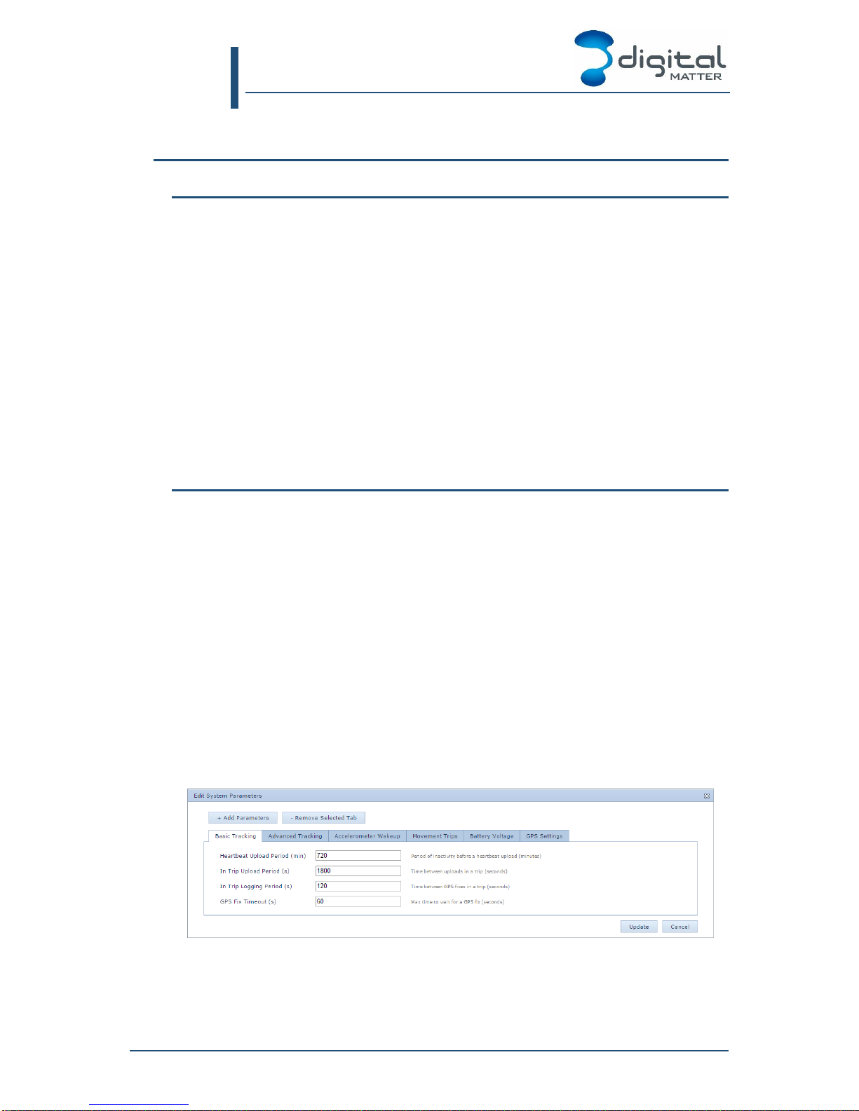
1. Configuration
The Heartbeat Upload Period is the maximum time between upload attempts. If the Remora
has not made an upload attempt for this long, it will attempt a GPS fix and an upload. If the
GPS fix fails it will still upload using the last known position, to ensure that battery and
Digital Matter Remora User Manual
9. Tracking Settings
REMORA-UM All information provided in this document is subject to legal disclaimers © Digital Matter 2015
Remora User Manual Revision 1.0 - 9 December 2015 Page 19 of 33
sensor levels are reported. However, if the upload fails (due to poor mobile signal, or
exhausted air time), it will not be retried until the next heartbeat or trip related upload.
The In Trip Upload Period is the maximum time between uploads once a trip is in progress.
It takes effect in parallel to the Heartbeat Upload Period. It is typically set several times
larger than the In Trip Logging Period, so that each upload contains many data points. If an
upload fails, it will not be retried until the next heartbeat or trip related upload.
If you require continuous uploads for the purpose of vehicle recovery, you should use
recovery mode (see section 11). There is currently no support for continuous in-trip uploads
outside of recovery mode. Upload periods of less than 5 minutes start to become very
inefficient. Please contact Digital Matter for assistance if your use case requires high
frequency uploads, and cannot be satisfied with a hardwired tracking solution.
The In Trip Logging Period is the time between GPS fix attempts. A lower logging period
increases the detail of the trip, but uses more battery for GPS reception. Failed GPS fixes
are not retried until the next heartbeat or trip related GPS fix.
The GPS Fix Timeout is the maximum time to wait for a GPS fix on each attempt. If your
application has very poor GPS signal, you may need to increase the timeout to several
minutes. In very good signal, it can be set as low as 10 seconds, which effectively instructs
the unit to give up as soon as it loses a direct view of the sky.
A lower timeout will give improved battery life, but may lead to tracking problems when the
signal is obstructed in urban environments. The default of 60 seconds should work well for
installs that are not enclosed.
The choice of upload period and logging period, together with the Remora’s mounting
position, are the primary factors in determining the ultimate battery life in your application.
Please see section 12 to learn how to estimate the battery life and choose appropriate
periods.
3. Advanced Tracking
The basic tracking cycle in section 2 can be modified in several ways:
The whole trip-tracking cycle can be disabled, leaving heartbeat uploads only
The number of uploads can be reduced to save battery
Additional uploads can be performed in response to accelerometer activity (jostling)
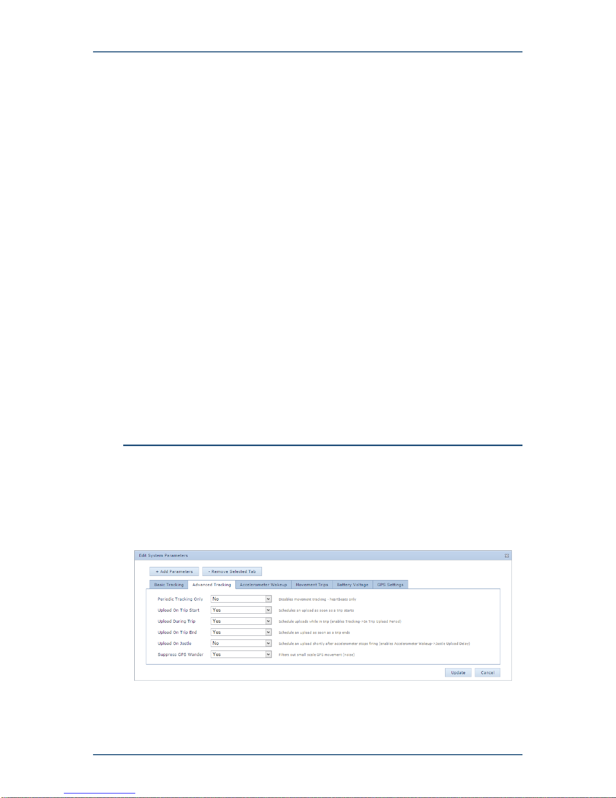
1. Configuration
The Periodic Tracking Only option disables trip tracking. In this mode, the Remora no longer
wakes up in response to jostling in order to check the GPS for movement. Instead, it will
stay in a low power sleep mode until the next scheduled heartbeat. For applications that

Digital Matter Remora User Manual
9. Tracking Settings
REMORA-UM All information provided in this document is subject to legal disclaimers © Digital Matter 2015
Remora User Manual Revision 1.0 - 9 December 2015 Page 20 of 33
only require low frequency tracking of the final location of an asset, this mode gives the
ultimate battery life. When only one or two uploads are required per day, the shelf-life of the
battery becomes the limiting factor.
The Upload On Trip Start, During Trip, and On Trip End options allow you to disable the
regular trip related uploads. If your application doesn’t require low latency notification of trip
starts, disabling the start of trip upload will save battery. Disabling Upload During Trip is
equivalent to setting the Basic Tracking -> In Trip Upload Period to an infinite value. Finally,
by disabling all three options, you can track trips without the overhead of trip uploads. In this
case the data will be stored and uploaded during the next heartbeat.
The Upload On Jostle option enables additional upload logic, intended to provide location
updates for movements that are too small to qualify as trips. When enabled, the Remora
schedules a heartbeat upload to occur at some time after the most recent jostle. If the
Remora is jostled constantly, this upload is pushed out further and further into the future up
to a configurable maximum. This effectively ensures that the final position after any small
movement will be uploaded, so long as GPS reception is not lost. Beware however that
constant jostling could lead to undesired uploads, each of which cost battery life.
The Suppress GPS Wander option filters out small movements from heartbeat uploads.
When enabled, position fixes for heartbeats are compared against the last known position. If
no significant movement is detected, the last known position is uploaded instead. This
default behaviour prevents GPS noise from causing apparent movement of stationary
assets. When using Upload On Jostle you should disable this filtering, to reveal the small
movements.
4. Accelerometer Wakeup
This section allows configuration of the wakeup rules for Basic Tracking, and the Upload On
Jostle timeouts from Advanced Tracking.
In order to detect trip starts reliably, the accelerometer is configured to be highly sensitive,
waking up on the slightest jostle. The Remora then checks for a legitimate trip start using
the GPS. Two mechanisms are available to prevent small vibrations during asset handling
from causing an excessive number of nuisance wakeups, for instance during the loading of
a trailer.
1. After each wakeup, the Remora sleeps for a short, fixed, time. This limits the
maximum rate of wakeups, and gives the asset an opportunity to get underway if it
really is beginning a trip. In this case, the first GPS fix will be more likely to detect
movement.
2. If too many jostle event are detected without any real movement being detected, the
Remora will temporarily ignore the accelerometer, and sleep for a longer time
before checking the GPS for movement. This provides a stricter limit on the
maximum rate of wakeups.
1. Configuration
Table of contents
Other Digital Matter Telematics GPS manuals


