Digital Systems Tytan SAT DS520 Guide

DS520.IM.EN.0205.008 Digital Systems
1
Technical documentation
Tytan®SAT DS520
Tytan®SAT DS520B
GSM/GPS/GLONASS device
for telemonitoring and supervision of vehicles
and technical appliances

DS520.IM.EN.0205.008 Digital Systems
2
Changes in document
DS520.IM.EN.0001.001
2016.05.16
- Document created
DS520.IM.EN.0001.002
2016.06.01
- Document reedited
DS520.IM.EN.0001.003
2016.07.13
- Description of SMS/GPRS remote commands (chap.10)
has been changed
- Tutorial for remote firmware upgrade (FTP) and
configuration changes have been added (chap. 11 and 12)
- Document reedited
DS520.IM.EN.0010.004
2016.11.17
- Changes related to implementation of power saving
modes
DS520.IM.EN.0013.005
2017.01.02
- Changes in point 3.2.3 and chapter 5. Added description
of further iButton scenarios, which report when IButton
has been taken off from the reader
- Corrected diagram of DS18B20 thermometer connection
DS520.IM.EN.0017.006
2017.06.12
- Additional analogue input mode (2.3, 6.4.1, 8.4.2, 8.4.3)
DS520.IM.EN.0202.007
2018.06.04
- Description of battery version added
DS520.IM.EN.0205.008
2018.08.21
- Corrected description of UPGRADE, GETCONFIG and
SETCONFIG commands

DS520.IM.EN.0205.008 Digital Systems
3
Table of Contents
1. General characteristics.................................................................................................................... 7
1.1 About....................................................................................................................................... 7
1.2 Basic characteristics ................................................................................................................ 7
1.3 Package contents..................................................................................................................... 8
1.4 View and dimensions............................................................................................................... 9
1.5 Functionality.......................................................................................................................... 10
1.6 Technical data........................................................................................................................ 11
1.6.1 Electrical characteristics:............................................................................................... 11
1.6.2 Mechanical features:..................................................................................................... 12
1.7 LED signals............................................................................................................................. 13
2. Device description......................................................................................................................... 14
2.1 Power supply......................................................................................................................... 14
2.2 Modem / GPS/GLONASS receiver ......................................................................................... 15
2.3 Analogue and digital inputs................................................................................................... 16
2.4 Digital outputs....................................................................................................................... 17
2.5 Accelerometer....................................................................................................................... 17
2.6 Digital interfaces and supported protocol ............................................................................ 17
2.7 Power supply from internal battery (only DS520B) .............................................................. 18
3. Data transmission to the server.................................................................................................... 20
3.1 Basic criteria for report generation (time-angle-distance) ................................................... 20
3.2 Additional reports generation and transmission when special events appear..................... 21
3.2.1 Reports generated by change of ignition state............................................................. 21
3.2.2 Reports generated by change of digital inputs ............................................................. 21
3.2.3 Reports generated by iButton identifiers...................................................................... 21
3.2.4 Reports concerning internal battery (DS520B only)...................................................... 22
3.2.5 Time cut-off between transmissions when special events appear............................... 22
4. Installation procedure ................................................................................................................... 23
4.1 Installation/changing of SIM card in DS520 .......................................................................... 23
4.2 Connection/disconnection of internal battery (DS520B only).............................................. 24
4.3 Mounting of DS520 unit in the vehicle.................................................................................. 26
4.4 Mounting of GSM antenna.................................................................................................... 27
4.5 Mounting of GPS/GLONASS antenna .................................................................................... 29

DS520.IM.EN.0205.008 Digital Systems
4
5. Driver’s identification/immobiliser function................................................................................. 31
5.1 Driver’s identification via iButtons (DS1990A)...................................................................... 31
5.1.1 Scenario no.1 - authorisation by any iButton................................................................ 31
5.1.2 Scenario no.2 - authorisation only by authorised iButton ............................................ 31
5.1.3 Scenario no.3 - authorisation by any iButton / ID sent only if iButton is in the reader 31
5.1.4 Scenario no.4 - authorisation only by authorised iButton / ID sent only if iButton is in
the reader...................................................................................................................................... 32
5.1.5 Data transmission to the server .................................................................................... 32
5.2 Immobiliser function –engine locking system...................................................................... 32
5.2.1 Use of immobiliser function for iButton scenario no.1 and no.3.................................. 33
5.2.2 Use of immobiliser function for iButton scenario no.2 and no.4.................................. 33
5.2.3 Emergency bypass of immobiliser function to start a vehicle ...................................... 33
5.3 Sound signalisation of iButton/immobiliser operation......................................................... 34
6. DS520 connection diagrams.......................................................................................................... 35
6.1 General diagram.................................................................................................................... 35
6.2 DS520 diagram connector description.................................................................................. 36
6.3 Connection of 1-wire devices/immobiliser function............................................................. 37
6.3.1 Connection of DS18B20 temperature sensors.............................................................. 38
6.3.2 Connections for immobiliser operation (iButton reader, immobiliser relay, buzzer)... 39
6.3.3 Connection of DS18B20 temperature sensors and iButton reader .............................. 40
6.4 Connection of analogue signals (voltage measurement)...................................................... 41
6.4.1 Connection of OEM float type sensor circuit ................................................................ 41
6.4.2 Connection of digital fuel level sensor (FLS) with analogue output 0-10V ................... 42
6.5 Connection of digital signals (On/Off)................................................................................... 43
6.5.1 NO (normally open) pushbutton switched to ground................................................... 43
6.5.2 NO (normally open) pushbutton switched to power supply voltage............................ 43
6.5.3 NC (normally closed) pushbutton switched to ground ................................................. 44
6.5.4 NC (normally closed) pushbutton switched to power supply voltage .......................... 44
7. Software for DS520 configuration and testing.............................................................................. 45
7.1 Configuration management .................................................................................................. 46
7.2 Signal monitor ....................................................................................................................... 47
7.3 Measurement data monitor.................................................................................................. 49
7.3.1 GPS/GSM/other............................................................................................................. 49
7.3.2 Voltage measurement................................................................................................... 51

DS520.IM.EN.0205.008 Digital Systems
5
7.4 iButton/1-wire monitor......................................................................................................... 51
8. Parameters of DS520 configuration.............................................................................................. 53
8.1 GSM/GPRS settings ............................................................................................................... 53
8.2 Reports/data ......................................................................................................................... 54
8.2.1 Reports: home network, powered ................................................................................ 54
8.2.2 Reports: home network, battery................................................................................... 54
8.2.3 Reports: roaming, powered........................................................................................... 54
8.2.4 Reports: roaming, battery ............................................................................................. 54
8.2.5 Data transmission.......................................................................................................... 55
8.3 Power supply/ignition ........................................................................................................... 57
8.4 Inputs..................................................................................................................................... 60
8.4.1 Data transmission.......................................................................................................... 60
8.4.2 AI0 (pin3, white/black) .................................................................................................. 61
8.4.3 AI1 (pin4, white/red)..................................................................................................... 61
8.4.4 DI2 (pin5, light blue)...................................................................................................... 62
8.4.5 DI3 (pin6, grey).............................................................................................................. 62
8.4.6 DI4 (pin7, blue).............................................................................................................. 62
8.4.7 DI5 (pin8, orange).......................................................................................................... 62
8.5 Outputs/immobiliser............................................................................................................. 64
8.6 iButton/1-wire....................................................................................................................... 65
8.6.1 iButton DS1990A identifiers.......................................................................................... 65
8.6.2 iButton drop-down menu.............................................................................................. 67
8.6.3 Temperature sensors DS18B20..................................................................................... 68
9. Configuration procedure and device start-up............................................................................... 69
9.1 Basic configuration................................................................................................................ 69
9.1.1 Parameters setting for basic configuration................................................................... 69
9.1.2 Checking device operation for basic configuration (with use of either PC or LEDs)..... 71
9.2 Advanced configuration ........................................................................................................ 73
9.2.1 GSM/ignition/power saving settings............................................................................. 73
9.2.2 Digital inputs.................................................................................................................. 73
9.2.3 Analogue inputs............................................................................................................. 74
9.2.4 Driver’s identification with iButton DS1990A/immobiliser........................................... 74
9.2.5 Temperature measurement by DS18B20 temperature sensors................................... 74
9.2.6 Change of report generation parameters ..................................................................... 75

DS520.IM.EN.0205.008 Digital Systems
6
9.2.7 Change of GPS odometer type ...................................................................................... 75
9.2.8 Change of operation mode –fixed/variable length of report....................................... 75
10. SMS/GPRS commands. Remote configuration and firmware upgrades................................... 76
11. Remote configuration and firmware upgrade via SMS............................................................. 82
11.1 New configuration downloading from FTP server and writing into DS520........................... 82
11.1.1 Command ...................................................................................................................... 82
11.1.2 Example 1 - downloading configuration file with automatically generated name....... 83
11.1.3 Example 2 - downloading configuration file with a given name................................... 83
11.2 Sending the file with current DS520 configuration to FTP server......................................... 84
11.2.1 Command ...................................................................................................................... 84
11.2.2 Example ......................................................................................................................... 85
11.3 DS520 firmware update via firmware file downloaded from FTP server.............................. 86
11.3.1 Command ...................................................................................................................... 86
11.3.2 Example ......................................................................................................................... 87
12. Remote configuration and firmware upgrade via GPRS ........................................................... 88
12.1 New configuration downloading from FTP server and writing into DS520........................... 88
12.1.1 Command ...................................................................................................................... 88
12.1.2 Example 1 - downloading configuration file with automatically generated name....... 89
12.1.3 Example 2 - downloading configuration file with a given name................................... 89
12.2 Sending the file with current DS520 configuration to FTP server......................................... 90
12.2.1 Command ...................................................................................................................... 90
12.2.2 Example ......................................................................................................................... 91
12.3 DS520 firmware update via firmware file downloaded from FTP server.............................. 92
12.3.1 Command ...................................................................................................................... 92
12.3.2 Example ......................................................................................................................... 93

DS520.IM.EN.0205.008 Digital Systems
7
1. General characteristics
1.1 About
Tytan®SAT DS520 is GSM/GPRS device designed for real time tracking of vehicles and cargo or
supervising technical objects. Device transmits location data (GPS/GLONASS position and speed) with
current parameters and events registered in monitored objects to the external server using UDP or TCP
protocol.
Due to analogue/digital inputs and 1-wire interface the device: a) measures data from sensors with
analogue output signal (e.g. from fuel level sensors), b) authorises access to the vehicle via iButton
identifiers, c) measures temperature via 1-wire sensors, d) monitors status of up to 5 switches (vehicle’s
door and bonnet/tailgate). Due to digital outputs the device allows users to control 2 circuits remotely.
The device is supplied with non-volatile memory which prevents data loss in case of no GSM network
coverage. In such cases, data are stored in non-volatile memory. Once connection is retrieved, data are
re-sent to the server.
DS520B version is equipped with internal LiPo battery. It allows the device to operate in emergency
conditions when power supply is lost.
1.2 Basic characteristics
•Power supply 12V/24V (voltage range 8-40V).
•Power consumption: average 14-36 mA (depending on configuration of transmission
intervals).
•Power saving modes: GPS sleep and deepsleep –min. power consumption less than 2mA.
•Additional 350mAh LiPo battery (available only in DS520B version).
•Up to 24h (conditions dependent) of operation without power supply (only DS520B).
•2 analogue inputs AI0/AI1, 0-10V/0-30V.
•4 digital inputs DI2/DI3/DI4/DI5.
•2 digital outputs OUT0/OUT1 (OC type).
•Built-in 3-axe accelerometer to detect drive condition without connecting ignition circuit.
•1-wire interface: iButton identifiers (DS1990A) and DS18B20 digital temperature sensors.
•List of up to 500 authorised iButton identifiers.
•Immobiliser function.
•Quad-band GSM/GPRS modem Simcomm SIM800C.
•External GSM antenna.
•Built-in GPS/GLONASS receiver Tytan Digital Systems GPS/GLONASS 1537 with
simultaneous observation of GPS and GLONASS satellites.
•External GPS/GLONASS antenna.
•32-bit Microchip MX7 microcontroller, 512kB Flash ROM, 128kB RAM.
•Built-in 4Mb memory to store data. Capacity: up to 50000 reports.
•Remote configuration and firmware upgrades via GSM/GPRS using FTP protocol.
•Two LEDs signalling device operation.
•USB port for configuration and device diagnostics.

DS520.IM.EN.0205.008 Digital Systems
8
1.3 Package contents
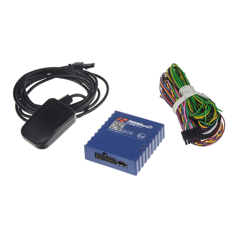
A complete set of DS520 includes:
•DS520 unit
•dedicated 11-wire harness (loom)
•GSM antenna
•active GPS/GLONASS antenna
SIM card of miniSIM type is not included in the set. The picture shows it only to specify the card size.

DS520.IM.EN.0205.008 Digital Systems
9
1.4 View and dimensions

DS520.IM.EN.0205.008 Digital Systems
10
1.5 Functionality
Data
transmission
Sending vehicle data via GPRS using UDP or TCP protocol in GSM network.
Limiting data transfer by collecting larger amount of data into packets.
Telemetry
Data collection from GPS/GLONASS satellite navigation systems,
analogue/digital inputs and 1-wire interface.
Vehicle location
Real-time transmission of vehicle geoposition, sampling grid dependent on
time, distance and vehicle heading angle.
Vehicle mileage
Mileage calculated by the device on the basis of GPS coordinates, regardless of
density of sampling positions. It is calculated incrementally among reports or
globally for one journey.
Roaming
Separate reporting configurations for operation in GSM home network and
roaming (intelligent roaming). Current country code and network provider name
are transmitted to the server.
Event log
memory
Data storage in non-volatile memory –prevents data loss in case of no GSM
coverage (once coverage is retrieved, data stored in memory is re-sent to the
server). Up to 50000 reports can be stored in memory (~85 hours of work with
10 reports generated every minute).
Remote firmware
upgrades
Remote firmware upgrades via GSM/GPRS - OTA (over-the-air) using FTP
protocol. Upgrade control via GPRS or SMS commands.
Remote
configuration
upgrades
Remote configuration reading and writing via GSM/GPRS - OTA (over-the-air)
using FTP protocol. Configuration reading and writing control via GPRS or SMS
commands.
Fuel
Fuel level readouts from two fuel level sensor circuits (OEM float type sensors
and FLS with analogue output 0-10V).
Driver’s
identification
Optional driver’s identification using iButtons (DS1990A).
Immobiliser
Optional immobiliser function that prevents unauthorised starting of the vehicle
engine.
Installation
Low power consumption and compact easy to install housing.
Optional simplified installation (power supply only, no ignition signal).
Virtual ignition
signal
Drive signal detection from readouts of both vehicle acceleration and vibration
and/or power voltage changes.
Device
diagnostics
Advanced diagnostic tools for PC use, improving device installation and start-up.
Internal battery
Device emergency operation in case of power supply lost. Depending on
configuration and conditions: from several minutes up to 24h.

DS520.IM.EN.0205.008 Digital Systems
11
1.6 Technical data
1.6.1 Electrical characteristics:
Min.
Typ.
Max.
Unit
Power Supply
Supply voltage
8
34
V
Power consumption –normal mode, voltage 12V
36
500
mA
Power consumption –GPS sleep mode, voltage 12V
15
mA
Power consumption –deepsleep mode (with accelerometer),
voltage 12V
1.9
mA
Power consumption –deepsleep mode (w/o accelerometer),
voltage 12V
1.2
mA
Average power consumption, deepsleep mode (w/o
accelerometer), 1 transmission every 5 minutes, voltage 12V
9.1
mA
Average power consumption, deepsleep mode (w/o
accelerometer), 1 transmission every 15 minutes, voltage 12V
3.9
mA
Battery type (DS520B only)
Lithium-Polimer (LiPo) LP303040
Battery capacity (DS520B only)
320
mAh
Analogue inputs AI0/AI1
Input voltage (range 0-10V)
0
10
V
Input resistance (range 0-10V)
100
kΩ
Input voltage (range 0-30V)
0
30
V
Input resistance (range 0-30V)
84
kΩ
A/D converter
12
bit
Digital inputs DI2/DI3/DI4/DI5
Input voltage
0
30
V
Input resistance
22
kΩ
Input resistance to power supply
47
kΩ
Input resistance to ground
47
kΩ
Voltage threshold (Low state)
1/3Vsupply
Voltage threshold (High state)
2/3Vsupply
Digital outputs OUT0/OUT1
Drain current (OFF state)
75
µA
Maximum output voltage (OFF state)
36
V
Maximum output current (ON state)
1.7
3.5
A
Electronic switch resistance(ON state)
250
mΩ
Protections
Reverse polarity protection
reversable, electronic
Device overcurrent protection
non-reversable,
internal fuse 3A
Output short-circuit protection
electronic 1.7A
1-wire line overcurrent protection
electronic, reversable, fuse50mA
1-wire overvoltage protection
electronic, 5.6V

DS520.IM.EN.0205.008 Digital Systems
12
1.6.2 Mechanical features:
Min.
Typ.
Max.
Unit
Temperature range
Storage temperature
-35
65
°C
Operating temperature
-25
55
°C
Housing
Length
75
mm
Width
54.7
mm
Height
15
mm
Weight (DS520)
52
g
Weight (DS520B)
60
g
Material
Poliamid PA66 + Fiber Glass
Connectors & cables
GPS connector
SMA
GSM connector
SMA
Cable loom connector
JST PHR-11
Wires in cable loom
UL1007 26AWG 12/0.12CU+PVC1.3
USB connector
mini USB
SIM card connector
mini SIM, foldable

DS520.IM.EN.0205.008 Digital Systems
13
1.7 LED signals
The device signals operation using two LEDs: red and green. Red LED signals the communication has
been established, i.e. DS520 is registered in GSM network and can transmit data to the server. Green
LED informs if received GPS/GLONASS signal allows to find actual geographical position of the device.
RED LED –GSM/GPRS connection
LED blinks approx. 10 times per second
no GSM connection
- no SIM card,
- SIM card invalid,
- SIM card lock,
LED flashes frequently (twice per second)
no GSM connection
- logging into GSM network not possible (roaming),
- sending GPRS data not possible,
- no GSM signal coverage,
LED flashes rarely (every two seconds)
proper GSM/GPRS connection (OK)
- DS520 registered in GSM network,
- GPRS data transmission to the server possible,
LED lights up for 4 seconds
data packet sent properly to the server (OK)
- the server has confirmed the receipt of report packet
from DS520.
GREEN LED –GPS/GLONASS position
LED flashes frequently (twice per second)
determining GPS/GLONASS position not possible
- GPS/GLONASS signal level too weak for accurate
geographical position,
- GPS/GLONASS antenna damaged, disconnected or
covered with metal elements,
LED flashes rarely (every two seconds)
GPS/GLONASS fixed position (OK)
- DS520 registered in GSM network properly,
- GPRS data transmission to the server possible.
WARNING!
- In normal operation both LEDs should flash infrequently (every 2 seconds).
- After power supply is connected (after restart) both LEDs light up continuously for 15 seconds.

DS520.IM.EN.0205.008 Digital Systems
14
2. Device description
2.1 Power supply
Power voltage / power consumption
The device can be used in vehicles with either 12V or 24V power supply. Power voltage is monitored
and its value is sent to the server by default. The power supply circuit is protected against reverse
polarity voltage. DS520B version is equipped with internal 350mAh LiPo battery.
Power saving modes / power consumption
The device has 3 modes for energy management: normal mode, GPS sleep mode and deepsleep mode.
In DS520B different energy management mode can be configured for operation with and without
power supply (chapter 2.7).
Normal mode
In normal mode the device consumes on average approx. 36 mA. Maximum value of the current spikes
during transmission does not exceed 500mA. GPS receiver is enabled constantly. GSM modem is
enabled constantly. GPRS session is not closed between sending reports. The device responds
immediately to SMS commands.
GPS sleep mode
In GPS sleep mode during parking the device disables GPS receiver under certain conditions, so that
power consumption is reduced to 14 mA. Conditions for disabling GPS receiver: ignition switch
(GLOBAL_IGNITION) is OFF, time to generate next report exceeds 120 seconds, GPS position is known
and fixed. GPS receiver is enabled 60 seconds before the scheduled generating of next report to ensure
time that is required to re-establish position. When ignition (GLOBAL_IGNITION) is detected as
switched on the GPS receiver is immediately enabled. GSM modem is enabled constantly. GPRS session
is not closed between sending reports. The device responds immediately to SMS commands.
The measurable results are reached when time condition exceeds 5 minutes.
Deepsleep mode
In deepsleep mode during parking the device, under certain conditions, disables GPS receiver and GSM
modem and also makes processor asleep, so that power consumption is reduced to 1.2 mA. Conditions
for entering deepsleep mode: ignition switch (GLOBAL_IGNITION) is OFF, time to generate next report
exceeds 120 seconds, USB cable disconnected. The device wakes up 60 seconds before the scheduled
generation of next report in order to ensure time limit required to re-establish GPS position, start up
GSM modem and establish GPRS connection. Additionally, the device wakes up (depending on
configuration) in the following cases: power supply voltage has been detected at the ignition signal
wire; accelerometer vibrations have been detected; increase of power supply voltage has been
detected.
Enabling the deepsleep mode results in meaningful power savings. The longer time between reports
when the ignition is switched off, the greater power savings are. If reports are set to be transmitted
every 5 minutes, the average current value is about 9mA. If reports are set to be transmitted every 15
minutes, the average current value is about 4mA.
WARNING!
(a) Waking up the device from deepsleep mode causes opening a new GPRS session and, depending on GPRS
service provider tariff charging system, can cause data transfer rounding to full tariff units. Therefore entering

DS520.IM.EN.0205.008 Digital Systems
15
deepsleep mode is reasonable when time between reports during parking reaches from a dozen to several
tens of minutes.
(b) The device wakes up from deepsleep mode by detecting ignition signal (GLOBAL_IGNITION). It is required
to connect analogue ignition signal wire or enable accelerometer based virtual ignition signal.
(c) Due to GSM modem deactivation the device receives and responds to SMS commands only after waking up
from deepsleep mode. Hence, when time between reports reaches 15 minutes the device can respond to SMS
command after approx. 15-20 minutes.
(d) When GPS sleep and deepsleep modes are used, GPS trace accuracy is decreased for a short period of time
after the device wakes up.
Detection of voltage changes - virtual ignition
The device can be optionally configured to detect engine operating from power voltage changes (the
effect of charging car battery by engine alternator) - generation of so-called virtual ignition signal. The
ignition switch-on signal appears when the voltage exceeds the set (upper) threshold for a time longer
than 5 seconds. If the voltage drops below a given (lower) threshold for longer than 5 seconds, the
ignition switch-on signal disappears.
2.2 Modem / GPS/GLONASS receiver
Modem
The device is supplied with Simcomm built-in industrial GSM modem SIM800C with the following
parameters:
•Quad-band 850/900/1800/1900MHz
•GPRS multi-slot class 12/10, mobile station class B
•Complied with GSM phase 2/2+: Class 4, Class 1
•SMS and GPRS handling
GPS/GLONASS receiver
The device is also supplied with GPS/GLONASS receiver manufactured on Digital Systems’ request:
•designation: Tytan Digital Systems GPS/GLONASS 1537
•handles systems of GPS, Glonass, Galileo, QZSS
•operates on the basis of simultaneous observation of GPS and GLONASS satellites
•protocol NMEA 0183 v3.01 (GGA,GSA,GSV,RMC,VTG)
•32 simultaneous channels
•high sensitivity: 161dBm
Both modem and GPS receiver require the use of external antennas, connected by SMA connector.
External antenna has significant advantage - it allows device installation in the safe place inside the
vehicle, not limited by the signal quality. Device can be installed inside metal containers, while external
antennas can be put in different places according to environmental conditions.

DS520.IM.EN.0205.008 Digital Systems
16
2.3 Analogue and digital inputs
2 measuring analogue inputs AI0/AI1, 0-10V/0-30V
High impedance inputs, non-polarized (without pull-up and pull-down), designed to measure voltage
0-10V or 0-30V. Measurement is taken with high resolution (10bit). It is possible to configure the
measurement range (0-10V or 0-30V).
Most commonly the inputs are used to connect 2 fuel level sensors with standardized analogue output
signal 0-10 V or OEM fuel level sensor.
Signal of both inputs is averaged in period of 10-120s, using complex and non-linear filtering
algorithms. It allows to eliminate signal fluctuations caused by changes of fuel level while driving.
Each input has a peak voltage detection function. It allows to handle fuel tank senders with pulsed
polarisation circuits - no need to use external analogue filters. If detector is enabled, calculated peak
voltage (for every second) is then averaged according to programmed parameters.
Analogue input value is transmitted to the server provided that data transmission from analogue
inputs and a given analogue input have been enabled.
There is an additional analogue input mode for the sensors powered from ignition circuit. Such sensors
give 0V signal when ignition is off. In this mode, the voltage is measured only if the ignition is on (starts
few seconds after ignition on detection). If the ignition is off the device transmits to server last valid
value of voltage, measured before the ignition was switched off.
4 universal digital polarized inputs (DI2/DI3/DI4/DI5)
dedicated ignition signal input DI5
The device is supplied with 4 universal digital inputs. Inputs are polarized inside the device up to half
of power supply voltage using approx. 50kresistor. Depending on the operation mode (INPUT+ or
INPUT-) input detects positive signal (voltage greater than 2/3 of power supply voltage) or ground
signal (voltage lower than 1/3 of power supply voltage). This solution allows to connect different
signals from vehicles as well as various additional sensors of both types, NO and NC.
Digital input has additional configurable options which refer to generating and sending reports to the
server (point 3.2.2), which means it can generate reports or force immediate data transmission to the
server at the following state changes: off→on and on→off.
Digital input value is transmitted to the server provided that data transmission from digital inputs has
been enabled and operation mode for digital input has been configured.
DI5 input is by default designed to operate as ignition input.

DS520.IM.EN.0205.008 Digital Systems
17
2.4 Digital outputs
2 digital outputs OUT0, OUT1
The outputs are connected to the device’s ground, using intelligent electronic keys with anti-short
circuit control up to 1.7A. Outputs are controlled from the server using GPRS or SMS commands. They
can also operate independently with regards to their functions in the device (immobiliser function - NC
immobiliser relay control).
2.5 Accelerometer
Virtual ignition signal (vehicle motion detection)
The device has a built-in 3-axe accelerometer, to detect vehicle motion and vibrations. The
accelerometer is used to generate the virtual ignition signal. The “ignition ON" condition is enabled in
configuration programmer if the vibrations appear for longer than 10 seconds. The “ignition off”
condition is detected if the vibrations are absent for at least 20 seconds.
2.6 Digital interfaces and supported protocol
1-Wire bus/iButton interface
The device has an interface to work with 1-wire bus systems - iButton identifiers (dedicated casings
made of stainless steel), digital temperature sensors(e.g. DS1820) and RFID readers equipped with 1-
wire interface. Software enables both identification of people and cargo, and temperature
measurement from up to four sensors.
The line designed to connect the reader is reinforced against surges and short-circuits and allows 1-
wire bus polarization in case circuits with greater power consumption are applied.DS520 enables
immobiliser function thanks to use of iButtons as described in chapter5.
USB interface
USB interface enables device configuration and firmware upgrades. It allows monitoring real time
values of measured data, using dedicated PC software.

DS520.IM.EN.0205.008 Digital Systems
18
2.7 Power supply from internal battery (only DS520B)
Battery
The device is equipped with internal 320mAh LiPo battery and integrated charging and protection
circuits. The battery allows the device to operate in emergency conditions when power supply is lost.
Power saving modes for battery operation
Different power saving modes can be configured for both operation with power supply and operation
without power supply (from internal battery). It allows the device to operate in “normal” power
saving mode when power supply is present and to go in “deepsleep” mode automatically when
power supply is lost.
Consequently, when power supply is present, no GPS localisation delay and high GPS trace accuracy
are maintained. When power supply is lost and the device is powered from internal battery, maximum
power saving is achieved and greater battery operation time is reached.
Report generation criteria for device operation with battery
Report generation criteria described in section 3.1. are configured separately for operation in different
conditions. Two sets of report generation criteria refer to DS520 (without battery): for roaming and
home network. For DS520B (with battery) these 2 sets are valid for operation with power supply.
Moreover, 2 additional sets can be configured: for operation from internal battery (without power
supply) in home network and for operation from internal battery (without power supply) in roaming
network.
Separate settings for operation with and without power supply allows maximising battery operation
time at a cost of trace accuracy.
Internal battery device operation time
Device operation time when powered from internal battery depends on several factors. Generally, the
internal battery allows the device to operate in emergency only. It is designed to uphold device
operation in order to enable sending information of power supply loss to the server. Such information
mostly means sabotage to tracker circuit. Battery allows the device to send approx. 30 transmissions.
While keeping full tracker functionality, the device operation time is several dozens of minutes.. When
power saving modes are used and report generation criteria are power-saving optimised it allows
reaching 24h of device battery operation in standby mode.

DS520.IM.EN.0205.008 Digital Systems
19
Server events and data concerning battery operation
DS520B device sends some information concerning battery to the server. Battery charge level (in
percent) and information about battery charging are sent. Every change of power supply (from
external power to internal battery and vice versa) generates a report that is immediately sent to the
server (point 3.2.5). If external power supply is present, every start and finish of battery charging
process also generates a report. If the device is in deepsleep mode, these events wake up the device
in order to send these reports to the server.

DS520.IM.EN.0205.008 Digital Systems
20
3. Data transmission to the server
Basic unit of data is so called "report", which is a record of data with GPS position of the vehicle and
additional data. Reports can be sent individually to the server (one record per one transmission) or can
be packed into packets containing several reports; one packet is sent with one transmission.
Every packet contains all data which have been acquired by the device.
Data from analogue and/or digital inputs, iButton identifiers and/or temperature sensor serial
numbers that are supposed to be transmitted by the device are set in configuration programmer –
parameters which name consists of two parts: curly braces with data identifier and designation staring
with “Sending …”, e.g. {C10} Sending authorised iButton ID.
If the device is configured to send data which are not available in the vehicle, the device:
- does not send these data at all (recommended setting - the length of report is variable, depending on
data availability in different vehicles),
- sends reports with special data value that means "data not valid/data not present", e.g. 28-1, 216-1,
232-1. This setting guarantees fixed length of the report however it is not recommended.
3.1 Basic criteria for report generation (time-angle-
distance)
The device generates the report if any of basic report generation criteria is met:
- distance travelled since last report is greater than configured threshold (default 250m),
- vehicle heading angle since last report is changed more than configured threshold (default 25°),
- time from last report is greater than configured threshold (default 60s/300s).
Time is configured separately for ignition ON (DRIVE) and ignition OFF (PARKING) states. The
configured time criteria for report generation are the timeouts of data transmission to the server.
Default settings are as below:
- distance 250m,
- angle 25°,
- 60 seconds (ignition ON),
- 300 seconds (ignition OFF).
For default settings, packet generation and its transmission to the server appears every minute when
ignition is ON or every 5 minutes when ignition is OFF.
In case angle, distance (or other) criteria have appeared more frequently than time criterion, one
packet contains several reports. Otherwise, one packet (one transmission to the server) contains one
report.
The criteria described above (distance/angle/time when IGN ON/time when IGN OFF) are configured
separately for 2 roaming situations:
- local network (no roaming),
- roaming –the device is outside the local network.
This manual suits for next models
1
Table of contents
Other Digital Systems GPS manuals
