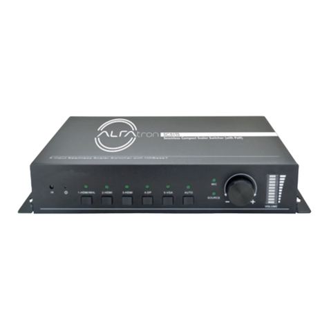
Digital Video Lab DSC938 User manual

1
HD/SD SDI Master Control Switcher DSC938
© 2016, DVLab http://www.dv-lab.com
Operation Manual.
HD/SD SDI Master Control Switcher DSC938

2
HD/SD SDI Master Control Switcher DSC938
© 2016, DVLab http://www.dv-lab.com
Contents
1. Product Overview ………………………………………………………………………….p.3
2. Features ………………………………..………………………………………………………р.4
3. Swicher's design ……….…………………………………………………………………..р.7
4. Input and output signals ………………………………………………………………..р.8
5. Multi-view …………………………………………………………………………………….р.10
6. Control Panel Overview …………………………..…………………………………….р.13
7. Main Unit – Rear Panel ………………………………………………………………….p.20
8. Supplied software ………………………………………………………………………….р.22
9. Connection diagram of the DSC938….……………………………………………р.25
10.Technical Specification …………………………………………………….……………р.26
11.Connection diagram of the analog audio Output…………..…………………р.29

3
HD/SD SDI Master Control Switcher DSC938
© 2016, DVLab http://www.dv-lab.com
Product Overview
The DSC938 Digital Video Switcher is a powerful but easy to use and cost-effective solution
that serves your production needs. Thanks to its convenient construction, the DSC938 is
suitable for portable or mobile applications.
The DSC938 's rich functional capabilities allow to use it for live broadcast, show, presentation,
interviewing as well as for production in studios.
Great attention was given to the visibility and intuitive control of the device.
DSC938 is the continuation of a series of compact SDI switchers from the "Digital Video Lab",
usage of new element basis with improved and optimized functions.
This series is characterized by maximum ease of use and in addition meets requirements of the
professional equipment.
The peculiarity of the DSC938 is new original blocks: a block of PiP effects (up to 4 windows on
a background); Two Chroma Key’s channels (with original automatic setting); Two Video
players’s channels (two built-in video players with high quality VC-3 on the SD card): two Still
Pictures.
Each of these blocks is always ready for use and has the same rights and capabilities as any
other inputs (the total number of the mixer’s inputs with the sources BLACK and BARS, is -18).
All inputs have corresponding buttons on the Preview and Program lines on the control panel,
which can be switched between each other and any other sources with any available
transitions of the switcher.
The mixer is available in two versions: the first version is structurally designed in the typical for
professional use form –main unit and control panel. The second version - is the portable
mobile video studio.

4
HD/SD SDI Master Control Switcher DSC938
© 2016, DVLab http://www.dv-lab.com
Features
Each input features its own frame synchronizer, which allows you to use cameras or
other devices that do not feature Genlock as well as input video from computer sources.
The audio input signals also pass through the synchronizers.
The mixer has 4 analog audio inputs (XLR connectors) which can be configured as 2
stereo inputs or 4 Mono.
The mixer has 2 analog audio outputs (XLR connectors).
The possibility of adjusting the dynamic range for digital and analog audio.
Input and output audio signals can be selected by the user with nominal levels -6, -12,
-18, -24 dBFs (from the OSD menu).
The possibility of assigning any input audio channels to any buttons of video sources
(for example - one audio channel for 4 switchable video inputs).
This mode is useful for working with an external analog audio mixer and shown in the
annex(p.60). The configuration is carried out via the PC.
Two built-in video players with high quality VC-3 on the SD card.
The possibility of playing video files and video playlists with “HD Playout” via HDMI
inputs of the switcher.
The possibility of mixing sound synchronous with video with a choice the type of sound
transition - V or Y.
Built-in background color signal, including "Black" and "Bars", which are operated as
independent sources and have the buttons on the Preview and Program lines on the
control panel.
Two built-in Still Pictures, which are operated as independent sources and have the
buttons on the Preview and Program lines on the control panel.
A total of 32 still pictures can be stored in the mixer's memory.
The possibility to include technological still picture on all inputs of the mixer.
That is each of the inputs can be switched to the still picture mode (For each input its
own still picture).
Built-in 1 kHz audio source with level 0, intended for testing and adjustment the level of
sound channels. It accompanies the internal source BARS.

5
HD/SD SDI Master Control Switcher DSC938
© 2016, DVLab http://www.dv-lab.com
Built in MultiView. The multiview output lets you see all 10 inputs of video, 2 video
players and 2 built-in still pictures on a single HDMI TV/monitor or SDI monitor! You can
see all of your cameras, tally indicators, graphics, preview and final program output all
on the same display at the same time. Also, the Multiview has indications of the input
and output analog and embedded SDI signals of the sound levels.
Menu (OSD) can be displayed on the Multiview also.
You can switch on and operate the menu (OSD) from the control panel.
The possibility of assigning the Multiview on any outputs of the switcher.
An additional HDMI output on which can be assigned any sources and Multiview.
Picture-in-Picture effect (PiP).
It is possible to enable the PIP’s preset, which is a combination of up to 4 windows
included in the background.
It is possible to change the following smaller windows settings:
size, crop, edging color, border width, location, sources for smaller windows and for
backgrounds).
All settings of the PIP’s presets are made and stored in the “Switcher Contol”program
from the PC.
4th PIP’s presets are written in the non-volatile memory of the switcher and saved
during restarts.
4th presets can be enabled on with the PIP1/PS1-PIP4/PS4 buttons.
It is possible to change the sources in the PIP’s windows from the control panel, and
quickly turn on or turn off the PIP’s windows either on the Preview or on the Program.
Two independent Chroma Key’s channels (with original automatic setting).
It is possible to overlay the PiP’s preset and Titles simultaneously on the video output
signal.
Two independent Logos.
1 Logo can be dinamic.
Total 8th logos can be uploaded from the PC in the switcher's non-volatile memory
and then to assign on independent buttons "Logo 1" and "Logo 2".
Each of the logos can be placed on the screen in an arbitrary place with the “Switcher
Contol” program from the PC .
Logo's can be changed from a PC and from console of the switcher.
1 Clock can be switch on/off with independent button.

6
HD/SD SDI Master Control Switcher DSC938
© 2016, DVLab http://www.dv-lab.com
Clock can be placed on the screen in an arbitrary place with the “Switcher Contol”
program from the PC .
The possibility of assigning signals from any inputs to all outputs of the switcher.
"TALLY" signals output .
F/W Upgrade; upload Still pictures; upload Logo and Clock,
control panel via Ethernet connection.
Quick quick configuration are made directly from the control panel and the on-
screen displayed menu on the multiscreen. The device configuration and rarely used
settings are made from the PC only.
Transitions: 6th WIPE special effects with reverse mode and Mix.
For each effect button, you can independently set the width of the transition border,
the border color and the transition speed.
It is possible to select the speed of the transition, including promptly from the control
panel of the switcher.
It is possible to remote control with “Switcher Contol” program(virtual control panel)
from the PC.
It is possible to choose with DIP-switch method of connection of the main unit and
control panel.
The 1-st method via RS-232.
The 2-nd method via Ethernet connection.
It is possible to connect a reserve +12В (9-15В) power supplier.
Wireless or wired via Ethernet Intercom system for 4 users - Option.
Wireless "TALLY" - Option.
Encoder H.265/H264 -Option.
4K Multiview (4 windows) - Option.

7
HD/SD SDI Master Control Switcher DSC938
© 2016, DVLab http://www.dv-lab.com
Swicher's design
The mixer is available in two versions: the first version is structurally designed in the
typical for professional use form –main unit and control panel. The second version - is the
portable mobile video studio.
Physical Installation of the main unit is 2 Rack Unit Size.,
Pic. Front panel of the DSC-938.
Pic. Rear panel of the DSC-938.

8
HD/SD SDI Master Control Switcher DSC938
© 2016, DVLab http://www.dv-lab.com
Pic. portable mobile video studio DSC-938.
Input and output signals
Video Inputs:
Inputs In1- In6, In9 and In10 - 8x HD/SD SDI , which can configured as 4x HD/SD SDI+ 4
xCVBS (IN3-IN6), 1x HDMI(DVI-D), 1x HDMI(DVI-D)/ Title.
Audio Inputs:
4 channels XLR balanced (works with external audio mixer) and can be setup as 2
Stereo pairs or 4 Mono's inputs .
10 x Embedded audio (2 ch) via SDI or HDMI.
Video Outputs:
Output 1 – Output 4- 4xHD/SD SDI,SDI (BNC)
1 x HDMI(DVI-D) output Multi View and 1 x HDMI(DVI-D) output assignable as
Multi View Output, Program ; Preview; Program Logo Free; Program Logo +Titles
Free, AUX.

9
HD/SD SDI Master Control Switcher DSC938
© 2016, DVLab http://www.dv-lab.com
Each of 4 SDI и 1 HDMI(DVI-D) Outputs of the switcher can be to assigned as:
1. Program output (PGM)
2. Program output (PGM) without Logos and Titles.
3. Preview output(PVW).
4. Program output (PGM) without Logos (Logo Free).
5. Any Inputs of the switcher(AUX).
6. MultiView
Audio Outputs
2 channels XLR balanced.
Output SDI Embedded Audio -One Stereo-pair (Group and Pair can be selected).
HDMI Out Embedded Audio.
Each audio source, including embedded and analog,
can be associated with any or several video sources.
Audio follows Video switching operation.
Audio level control of the all inputs and master audio level output
via On Screen Display Menu and DVLab’s Switcher Utilities.
DSC-938 has 8 SDI inputs and 2HDMI(DVI-D).
4 Inputs (IN3-IN6) can be switched as SDI inputs or CVBS inputs from Menu(OSD) or
DVLab’s Switcher Utilities.
All Inputs have frame synchronizers.
In SD mode the switcher can to use HD and SD sources simultaneous and make
transitions between them.
Also technological slides can be asign instead of the each inputs:
technological slides uploads on IN1-IN8 from PC and IN9-IN10 from SD card.
All outputs can be switched from HD mode to SD mode.
For SD mode, you can select 2 formats -4: 3 or 16: 9.
Video signal processing in the switcher is performed with a 10-bit resolution.
For the option selected of the Outputs setup, the output SDI signals always contain a
embedded audio signals, if there is one in the video signals.
Preview and Program signals have each own audio signals.
Audio signals are assigned to the buttons from the Menu and from the PC with DVLab’s
Switcher Utilities.
A group and a pair of the SDI audio signals sets with DVLab’s Switcher Utilities from
the PC.

10
HD/SD SDI Master Control Switcher DSC938
© 2016, DVLab http://www.dv-lab.com
MultiView
In order to work successfully with the switcher requires a display with a screen
resolution of 1920 × 1080i pixels and HDMI input.
These might be the FullHD LCD TVs or computer monitors that have HDMI or DVI inputs
and supports the resolution of 1920X1080i 50 Hz.
The display is not included in the supply.
But the portable mobile version of the DSC-938 has own display.
The multiview output lets you see all 10 inputs of video, 2 video players and 2 built-in still
pictures on a single HDMI TV/monitor or SDI monitor! You can see all of your cameras, tally
indicators, graphics, preview and final program output all on the same display at the same
time. Also, the Multiview has indications of the input and output analog and embedded SDI
signals of the sound levels.
Menu (OSD) can be displayed on the Multiview also.
You can switch on and operate the menu (OSD) from the control panel.

11
HD/SD SDI Master Control Switcher DSC938
© 2016, DVLab http://www.dv-lab.com
Service information on the MultiView screen:
1) Channel names for input windows and PGM / PVW labels for output windows.
2) Indications of the selected inputs (for PGM / PVW / PIP).
3) The type of the current transition effect (seven pictures are displayed,
Corresponding to the seven buttons on the remote control (six selected
Wipes and MIX),
The current effect is marked with a backlight.
4) Indication of the type of audio mixing at the Program output (V or X).
5) Current time.
6) On-screen menu (displayed over the top of other windows when switched on).
7) Audio signal indicators.
8) Information about the type of switcher’s control: PC CONTROL or Console
CONTROL.
CONSOLE Indications.
The yellow indicator shows which source is selected on
the Preview.
The red indicator shows which source is selected on
the Program.
WIPE transition. The selected transition effect is
indicated by highlighting the corresponding icon on the
MultiView.

12
HD/SD SDI Master Control Switcher DSC938
© 2016, DVLab http://www.dv-lab.com
Mix transition. The selected transition effect is
indicated by highlighting the corresponding icon on the
MultiView.
Indication of the type of audio mixing at the Program
output X (A/B cross fade)
"X" is a transition with simultaneous reduction of one
signal and an increase the other.
Indication of the type of audio mixing at the Program
output V(Fade out A then Fade in B).
«V»- is a transition with fade out of one signal and than
fade in the other.
Titles, PiP1, PiP2
Labes on the thumbnail “Titles”, “Chroma1”,
“Chroma1” ,“PiP1”, “PiP2” - show which sources are
selected as video effects “PiP”,”Croma” or Titles.
The type of switcher’s control.
PC CONTROL or Console CONTROL.
"PC Control" appears when the switcher is connected to
the PC and the "PC Control" button is pressed.
In this mode, operation from the remote control is
blocked. And control is transferred to the virtual console
program. If the “PC Control” button is not pressed (not
lit), the switcher is operate from the remote control and
the on Multiview displays “Console Control”.

13
HD/SD SDI Master Control Switcher DSC938
© 2016, DVLab http://www.dv-lab.com
Control Panel Overview
The control panel is connected to the main unit by a cable with DB9M connectors.
The cable length can be up to 20 m.

14
HD/SD SDI Master Control Switcher DSC938
© 2016, DVLab http://www.dv-lab.com
Also, the control panel can be connected to the base unit via Ethernet.
In this case, must be connected (+ 12V) power supplier to the control panel.
Pic.. Rear side of the control panel.
A free utility for docking the control panel with a mixer is called ControlPanelConfig.exe,
which can be downloaded from the following link:
http://dv-lab.com/files/files3/ControlPanelConfig.zip
Рис. free utility for docking the control panel with a mixer ControlPanelConfig

15
HD/SD SDI Master Control Switcher DSC938
© 2016, DVLab http://www.dv-lab.com
On the rear panel of the console is a DIP switch, which switching the type of the
connecting mode to the main unit:via DB9F or via Ethernet.
- When the control panel is connected to the mixer via DB-9 F, the DIP switch is
turned on in the upper position.
- When the control panel is connected to the mixer via Ethernet, the DIP switch is
turned on in the lower position.
PROGRAM Line
The Program line of buttons is the active channel, this is the live output. The active channel will
appear as the Program Output (PGM). You can switch or CUT from one video source to
another directly on the Program row. You will see the multi view PGM output change as you
press different keys along this top line of buttons.
PRESET Line
The Preset line is the cued channel, this channel will appear in the PST or Preview window. The
Preset line selection decides which input will be transitioned next when using any of the
transition controls.

16
HD/SD SDI Master Control Switcher DSC938
© 2016, DVLab http://www.dv-lab.com
The configuration of the inputs is carried out from the PC by the “DV-Lab” software
utility and from Menu (OSD) on the MultiView
Operation buttons
CUT TAKE
This performs a simple immediate switch
from the current main source to the
selected sub source. The selected
transition wipe or dissolve is not used.
AUTO TAKE
This performs an automated switch from
the current program source to the selected
preset source. The selected transition wipe
or dissolve will also be used. The timing of
the transition is set by the chosen Speed
button.
T-BAR.
This performs a manually controlled
transition from the current program source
to the selected preset source. The selected
transition wipe or dissolve will be used.
When the T-Bar has travelled as far as it
can go, the transition between sources is

17
HD/SD SDI Master Control Switcher DSC938
© 2016, DVLab http://www.dv-lab.com
complete. The T-Bar has indicators next to
it, which light when the transition is
complete. The T-Bar can be operated in
one of two modes which is chosen by a
menu option.
OSD MENU Options
When the “Menu” button is pressed the
Main Menu list is displayed on the Multi-
view Display.
With the cursor buttons you can navigate
through the menu items and change the
parameters.
Once the chosen setting has been
confirmed with the ENTER button it is
stored within the switcher’s non-volatile
memory.
PGM to MVW – switching On the full-size
image of the Program output on the
MultiView.
Transition Selection
MIX Pressing this button selects a basic
A/B Dissolve for the next transition.
Wipe, Pressing this button you can to
select one of six the Wipe’s effects .

18
HD/SD SDI Master Control Switcher DSC938
© 2016, DVLab http://www.dv-lab.com
PiP (“picture in picture”) control
The operative control of PIP’s windows is
carried out from the control panel using
the buttons "PIP" in the Program line and
in the Preview line. The PS1-PS4 buttons
select the PIP preset that you want to
enable.
With buttons PIP1-PIP4 you can switch on
or switch off the windows in the PIP’s
presets and also quickly change the
sources in the windows of the PIP’s
presets.
TITLE APPLICATION
Pressing this button "Titles PRVW" (including the overlay of
captions on the preview output) and "Titles PGM" (enabling
the overlay of titles to the program output).
CHROMA effects control. The CHROMA 1,2 buttons are
used to switch on / off the Chroma 1 (2) mode and select
the "Foreground" and "Background".

19
HD/SD SDI Master Control Switcher DSC938
© 2016, DVLab http://www.dv-lab.com
LOGO1 , LOGO2 и CLOCK.
The LOGO 1 and LOGO 2 and Clock buttons are used to
display preselected logos on Preview and Program outputs.
When the buttons are active the selected logos and clock is
shown. These logos and clock are selected from the
switcher’s memory and positioned using a “DV-Lab”
software utility.
This button enables the transfer of control from the PC. When
the button is pressed, the switcher is controlled by the “Virtual
Switcher” from the PC.
The FS button allows the user to toggle between the still image
of the Frame Store or the live video input also connected to that
same video channel.
Shift-modifier button, which allows you to not increase the
number of buttons and increase the number of switched
inputs / sources and also allows to perform several functions
withone button.
Players control sbuttons and transition speed control

20
HD/SD SDI Master Control Switcher DSC938
© 2016, DVLab http://www.dv-lab.com
Main Unit – Rear Panel
HDMI(DVI-D). MULTIVIEW OUT (OUT6)
ETHERNET
This RJ45 Ethernet port is used to connect the
DSC-938 to a PC for remote control, or to update the
unit’s firmware, or to configure the switcher, or for
connecting the control panel.
CONSOLE
This 9pin D-Sub connector is used to connect the
Control Panel / Keyboard to the rear of the DSC-938
Main unit.
TALLY
Разъем DB-15F (10 ключей)
AUDIO INPUTS
4 channels XLR balanced (works with external audio
mixer) and can be setup as 2 Stereo pairs or 4
Mono's inputs .
Table of contents
Popular Switch manuals by other brands
Edimax
Edimax EU-HB4M Specifications
Intermatic
Intermatic RC2103S Owner installation instruction manual
Dell EMC
Dell EMC PowerSwitch N2200-ON Series installation guide
Brocade Communications Systems
Brocade Communications Systems ServerIron ADX 12.4.00 Manual guide

Tenda
Tenda TEH1208 user manual

Versitron
Versitron SG71090 installation guide

