DIGITAL YACHT SPL2000 User manual

USER MANUAL SPL2000 - VR1.00
Installation and User Manual
SPL2000 Splitter for Class B AIS Transponders

DIGITAL YACHT LTD
SPL2000 User Manual
IMPORTANT INFORMATION
Before operating the unit you should familiarise yourself with the complete user manual supplied with the product.
Electrical safety
Make sure the power supply is switched off before you make any electrical connections to the unit.
Product installation
This equipment must be installed in accordance with the instructions provided in this manual. Failure to do so
could result in poor performance, personal injury and/or damage to your vessel and/or connected equipment.
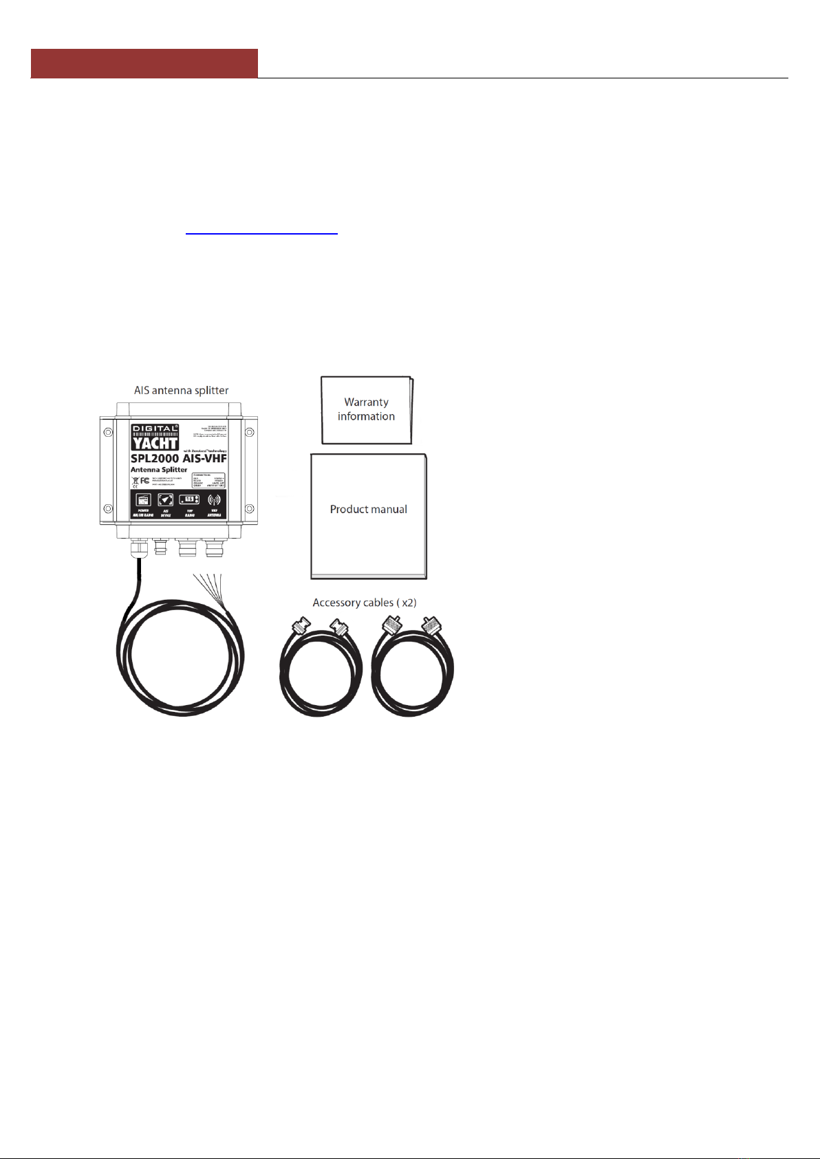
Cables
The supplied cables should not be cut, shortened or lengthened as this will reduce the performance of the
product. If longer cables are required you should obtain a replacement cable from an appropriate supplier.
Compass Safe Distance
The compass safe distance of this unit is 0.5m or greater for 0.3° deviation.
RF emissions notice
The information provided in this section assumes the AIS antenna splitter is connected to an AIS Class B
transceiver.
The AIS antenna splitter generates and radiates radio frequency electromagnetic energy. This equipment must
be installed and operated according to the instructions contained in this manual. Failure to do so can result in
personal injury and/or the malfunction of the AIS antenna splitter and/or the AIS transceiver it is connected to.
Caution: Never operate the AIS antenna splitter unless it is connected to a VHF antenna.
To maximise performance and minimise human exposure to radio frequency electromagnetic energy you must
make sure that the antenna is mounted at least 1.5 meters away from the AIS antenna splitter and is connected
to the AIS antenna splitter before power is applied.
The system has a Maximum Permissible Exposure (MPE) radius of 1.5m. This has been determined assuming
the maximum power of the AIS transceiver and using antennas with a maximum gain of 3dBi. The antenna
should be mounted 3.5m above the deck in order to meet RF exposure requirements. Higher gain antennas will
require a greater MPE radius.
Do not operate the unit when anyone is within the MPE radius of the antenna (unless they are shielded from the
antenna field by a grounded metallic barrier). The antenna should not be co-located or operated in conjunction
with any other transmitting antenna. The required antenna impedance is 50 ohms.
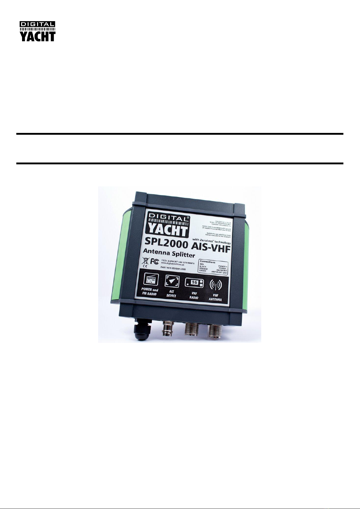
In accordance with a policy of continual development and product improvement the Digital Yacht SPL2000
hardware and software may be upgraded from time to time and future versions of the Digital Yacht SPL2000 may
therefore not correspond exactly with this manual. When necessary upgrades to the product will be accompanied
by updates or addenda to this manual. Information contained in this manual is liable to change without notice.
Digital Yacht Ltd. disclaims any liability for consequences arising from omissions or inaccuracies in this manual
and any other documentation provided with this product.
© 2012 Digital Yacht Ltd.
If after reading this manual and checking our website for FAQs, you have any further questions please call:
01179 554474
INTL + 44 1179 554474

DIGITAL YACHT LTD
SPL2000 User Manual
1. Introduction
Congratulations on the purchase of your SPL2000 Class B AIS Splitter. It is recommended that your Splitter is installed by
a professional installer.
This User Manual will provide all of the information you need to install and operate the SPL2000, but for
the most up to date information about this product it is recommended that you visit the Support section
of our website www.digitalyacht.co.uk
2. Before You Start
In the SPL2000 packaging should be the following items;
You will need the following items and tools to complete the installation:
Class B AIS Transponder.
Pre-installed VHF Antenna and cable.
Access to 12V DC or 24V DC power supply where the unit is to be installed, via a 1A rated fuse or circuit breaker.
Connector block or junction box for power connections.
Four M4 (no. 6) screws or other fixings appropriate to the mounting location.
It is not recommended to use this AIS Antenna Splitter with a Class A Transponder, Aids to Navigation
Transponder or AIS Base Station..

DIGITAL YACHT LTD
SPL2000 User Manual
3. Installation
Before starting installation select a suitable location for the SPL2000 Class B AIS Splitter. The unit is water resistant;
however it should be installed below deck in a dry location. When locating the unit you should consider:
Routing of power and antenna cables to the unit.
Provision of sufficient space behind the unit for cable connections.
Maintaining the compass safe distance of 0.5m.
Visibility of the front panel indicators.
Installation Diagram
Below is a typical installation diagram of the SPL2000 being connected to a Class B Transponder.
Installation Step 2 –Mechanical Fixings
Access to the fixing holes is achieved by removal of the two green decal strips down each side of the SPL2000.
Once fixed in place, the green decal strips can be clicked back in place.

DIGITAL YACHT LTD
SPL2000 User Manual
Secure the Splitter to a flat surface in the selected location. Use four M4 wood screws or other fixings suited to
the material the unit is being fixed to. The unit may be installed in any orientation
Fixing location drawing
Installation Step 3 - Power
Provide power connections to the unit. Power is connected to the four core “POWER/AM-FM Radio” cable on
the Red and Black wires. The Red wire is the positive (+) connection. The Black wire is the negative (-)
connection.
Connect the stripped wires to the nearest source of primary 12V or 24V DC power. Ensure that the supply is
connected via the supplied 1A fuse or suitable circuit breaker. Add the fuse in the positive power connection
to the unit if necessary.
The SPL2000 Class B Splitter is designed for 12V or 24v DC systems.
Do not apply power to the SPL2000, until all of the antenna and coax connections are correctly made.
Installation Step 4 –Antenna Connections
The SPL2000 is supplied with two coax cables to connect to a Class B Transponder and VHF radio. One cable is
a BNC to BNC cable for connection to the AIS Transponder, while the other cable with the larger PL259 (UHF)
type connectors is for connecting the SPL2000 to the VHF radio.
Ensure you connect the boat’s existing VHF antenna, which will have also have a PL259 connector on it to the
correct SO239 connector on the SPL2000.
On the “POWER/AM-FM Radio” cable you have two connections (Orange+ and Green-) that can be wired to the
antenna connection on an AM or FM radio. This will give better reception than most normal AM/FM radio
antennas, benefitting from the extra height of the VHF antenna and higher gain.

DIGITAL YACHT LTD
SPL2000 User Manual
4. Operation
Turn on the 12V or 24v power to the SPL2000.
Ensure the VHF radio and Class B AIS Transponder are turned on.
Verify that the green “POWER”LED indicator on the front of the unit is illuminated,
Listen to channel 16 or another VHF channel and confirm that you can hear voice communication.
Press the PTT button on your VHF and ensure that the Yellow “VHF” LED indicator on the front of the unit
illuminates whilst the PTT button is pressed.
Watching the Yellow “AIS” LED, ensure that at regular 3 minute intervals or 30 second intervals if you are
underway (SOG > 2 Knots), the Yellow “AIS” LED briefly illuminates when the AIS Transponder transmits its
position.
If your Class B AIS Transponder was supplied with configuration/diagnostics software like proAIS, run this
software and check that the Power (SWR) readings are still within the acceptable value range.
Installation is now complete.
5. Troubleshooting
Problem
Solutions
Power LED not illuminated
Check power supply connections and fuse or circuit
breaker.
Check polarity of power supply connections.
Check power supply voltage.
‘VHF’ LED does not illuminate when
VHF Radiotelephone is transmitting.
Check the antenna output of the VHF radiotelephone is connected
to the antenna splitter input labelled ‘VHF’.
‘AIS’ LED does not illuminate when
AIS Transponder is transmitting.
Check the antenna output of the AIS transponder is connected to
the antenna splitter input labelled ‘AIS’.
Clicks or pops are heard from a
connected FM broadcast receiver.
This is normal and may occur during VHF or AIS transmission.
VHF or AIS Transmission is reduced
A small reduction in transmission range is normal and due to the
insertion loss of the antenna splitter
Both the “AIS” and “VHF” indicators
illuminate when the VHF Radio is
transmitting
This is normal operation with some brands of VHF Radio and not a
fault. Function of the antenna splitter is unaffected.

DIGITAL YACHT LTD
SPL2000 User Manual
6. Specification
Parameter
Value
Dimensions
150 x 155 x 37.5 mm (L x W x H)
Weight
725g
Voltage supply
DC 9.6 to 31.2V
Current consumption
<150mA at 12VDC
VHF and AIS frequency range
156MHz to 163MHz
Insertion loss AIS & VHF receive paths 0dB
0dB
Insertion loss AIS & VHF transmit paths
<1dB
Max input power, AIS port
12.5W
Max input power, VHF port
25W
Min input power, VHF port
100mW
AIS, VHF and Antenna port impedance
50 Ohms
FM port impedance
75 Ohms
Switching time, receive to AIS transmit
<10 us
Switching time, receive to VHF transmit
<10us
Operating temperature:
-10ºC to +55ºC
Ingress protection
IPx5
Table of contents
Other DIGITAL YACHT Cables And Connectors manuals
Popular Cables And Connectors manuals by other brands

Walther-Werke
Walther-Werke basicEVO instruction manual

Extron electronics
Extron electronics Cable Cubby 100 installation guide

Leviton
Leviton QuickPort Duplex 106 Specifications

YOKOGAWA
YOKOGAWA WU11 instruction manual

Tecnosystemi
Tecnosystemi smart clima SCC300017 user manual

Tektronix
Tektronix P6700 Series instruction manual