DIGITAL YACHT aquaPro Datasheet
QUICK START AquaPro PC VR2.00
Installation & Quick Start Guide
Aqua PC Range –AquaPro Version 2

DIGITAL YACHT LTD
AquaPro 2 PC Quick Start Guide
1. Introduction
Congratulations on the purchase of your AquaPro PC. It is recommended that your new computer is installed by a
professional installer.
Do not disconnect the White wire from the Red on the main power/data cable until you have read and
understood the Remote Switch operation (Installation Step 3+4) explained in this Quick Start Guide.
2. Before you start
You will need the following items and tools to complete the installation:
A USB Keyboard and Mouse
A suitable Monitor with VGA or HDMI input
Access to 12V or 24V DC power supply where the unit is to be installed
Crimps, terminal block or other connectors suitable for connecting DC/Signal wiring
M3 or M4 screws or other fixings appropriate to the mounting location
If the AquaPro PC has Windows pre-installed, you will need to authorise this copy of Windows by either connecting the
computer to the internet or ringing the Microsoft automated telephone authorisation system.
Other optional items you may wish to have with you during installation include;
Suitable USB Memory stick for transferring software and data
A momentary action push button switch (push to make) if you want a remote power switch
A powered USB hub if you intend to connect more than 6 USBs devices to the AquaPro PC
Original CDs/DVDs of the software you wish to install on the AquaPro PC
3. Installation
Before starting installation select a suitable location for the AquaPro PC. The unit is not water resistant and should be
mounted in a dry location where it will not come in to contact with water or excessive moisture. When locating the unit you
should consider:
Routing of power and USB cables to the unit
The unit must be located in a dry location
Ensure that the unit is sited in a well ventilated area, to avoid excessive heat build up
Provision of sufficient space behind the unit for cable connections
Getting access to the AquaPro PC for plugging in USB devices and loading CDs/DVDs
Maintaining the compass safe distance of 0.5m
Installation Step 1
Run a suitable 12v or 24v supply to the location where the AquaPro PC will be mounted.
The AquaPro PC normally consumes around 4A at 12v but will consume more power if you are powering lots of
USB devices from the AquaPro PC.
Ensure a suitable in-line fuse is fitted or circuit breaker (maximum 10A).
Run any USB or NMEA interfacing cables to the location where the AquaPro PC will be mounted.
Do not make any connections yet.
The USB Interface Standard specifies that USB cables should be no longer than 5m without using a
special powered USB extender cable –ensure that the total USB cable length from the AquaPro PC to any
USB device is < 5m.
DIGITAL YACHT LTD
AquaPro 2 PC Quick Start Guide
Installation Step 2
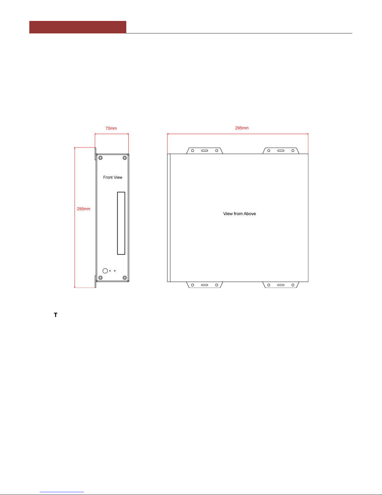
The AquaPro PC is supplied with four mounting brackets which are screwed (wrong way round) to the base of the
AquaPro PC for transit. Unscrew the brackets, reverse them and screw them back in place. Use suitable fixings
(not supplied) to fix the AquaPro PC to a flat surface –using the dimensions and details shown in the drawing
below. Note that the unit may be installed in any orientation.
Fixing location drawing
The AquaPro PC is also supplied with two plastic stands that can be fitted if the AquaPro PC is to be
desk mounted as you would in an office or home environment –these are definitely not recommended for
installation of a boat
DIGITAL YACHT LTD
AquaPro 2 PC Quick Start Guide
Installation Step 3
On the rear of the AquaPro PC is a single black cable that has three wires. This is the Power cable. Connect the
Red (+) and Black (-) wires in the Power cable to the ship’s 12v or 24v supply.
Ensure that the supply is connected via a suitable fuse or suitable circuit breaker (in the positive power
connection). A 5A fuse/circuit breaker is recommended for most installations and 10A is the maximum value that
should be used.
You will note that there is a White wire soldered to the Red wire. This is the remote switch wire and should always
be connected to the Red wire if no remote switch is required. The AquaPro PC will not power up correctly if the
White wire is disconnected from the Red wire and no remote switch is fitted –see wiring diagram.
Do not try to turn on the AquaPro PC yet.
Installation Step 4
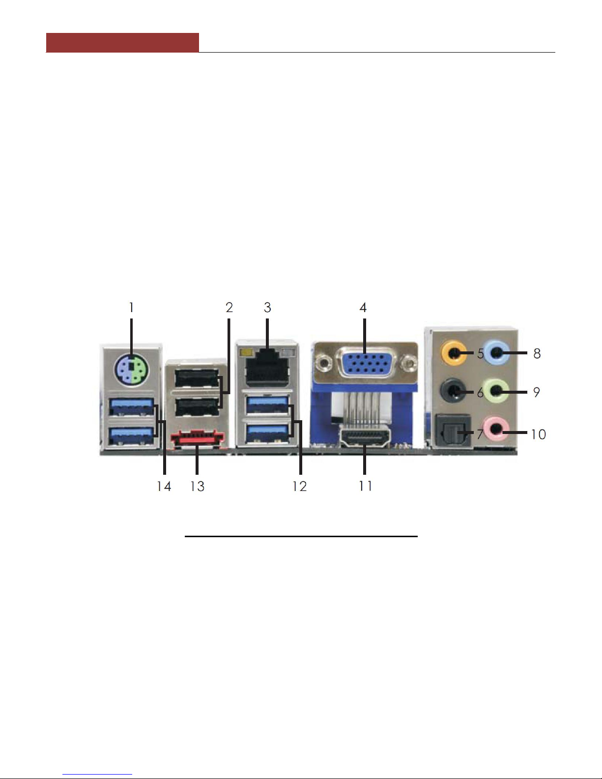
The connections on the rear of the AquaPro PC are as follows;
Number - Item
1 - PS2 Keyboard Connector
2 - USB 2.0 Ports 2 + 3
3 - LAN (RJ45) Ethernet Port
4 - VGA Port for Monitor
5 - Centre Sub Woofer Port (Orange)
6 - Rear Speaker Out Port (Black)
7 - Optical SPDIF Output
8 - Line In Port (Light Blue)
9 - Line Out Port (Lime)
10 - Microphone Port (Pink)
11 - HDMI monitor
12 - USB 3.0 Ports 4+5
13 - eSATA Port
14 - USB 3.0 Ports 1+2

DIGITAL YACHT LTD
AquaPro 2 PC Quick Start Guide
Connect a USB mouse and keyboard to any of the six USB ports on the AquaPro PC
Connect a suitable monitor or monitors to the VGA and/or HDMI connectors on the AquaPro PC
To connect a remote power switch for the AquaPro PC, at another location in the boat, simply remove the white
wire from the red wire and connect the white wire to the ship’s supply (+12v or +24v) via a SPST toggle switch as
shown below.
Once all devices are correctly connected to the AquaPro PC ensure the 12v or 24v power is connected i.e. the
circuit breaker is ON (if fitted) and then turn on the remote toggle switch and the AquaPro PC will power up. As
you turn on the remote switch, the Power and Hard Disk LEDs on the front face of the AquaPro PC should come
on as the PC starts it’s power up sequence.
NOTE –when using the remote switch configuration, there is a 5 second delay between pressing the switch and
the power up or power down sequence initiating.
Installation is now complete.
White
Wire
SPST Toggle
Switch
+12v/24v
Supply

DIGITAL YACHT LTD
AquaPro 2 PC Quick Start Guide
APPENDIX A
Additional Information for optional ZDIGNMUP
Opto-Isolated four port NMEA multiplexer
The following information is only applicable for Aqua Pro PCs that have been fitted with the optional Opto-Isolated four
port NMEA multiplexer (Actisense NDC-04).
On the rear of Aqua Pro PCs, fitted with an NDC-04, will be a 10 wire multi-core cable that has four NMEA 0183 inputs
and one NMEA 0183 Output. The colour coding is shown below:
Aqua Pro PC (NDC-04) Cable
Colour
Signal
Red
NMEA IN1 +
Blu
NMEA IN1 -
Orange
NMEA IN2 +
Brown
NMEA IN2 -
Yellow
NMEA IN3 +
Green
NMEA IN3 -
White
NMEA IN4 +
Black
NMEA IN4 -
Purple
NMEA OUT+
Grey
NMEA OUT-
The NMEA Multiplexer is connected internally to the Aqua Pro PC motherboard and the latest drivers and been installed
and tested. The default settings are for all four ports to accept 4800 baud NMEA 0183 data and to automatically multiplex
this through to the Aqua Pro PC on COM Port 3 at 38,400 Baud. The same data will also appear on the NMEA OUT –
purple and grey wires.
Also installed on the Aqua Pro PC is the NDC-04 Control Centre software which can be used to configure the ports and
control the way NMEA data is handled by the multiplexer. This software is very powerful and allows the NDC-04 to be
configured for many different types of installation. It is strongly recommended that you consult with the dealer that
supplied the Aqua Pro PC before changing any settings.
A PDF manual for the Actisense NDC-04 is included on the Aqua Pro PC and more information can be found at:-
www.actisense.com
Table of contents
Other DIGITAL YACHT Desktop manuals


