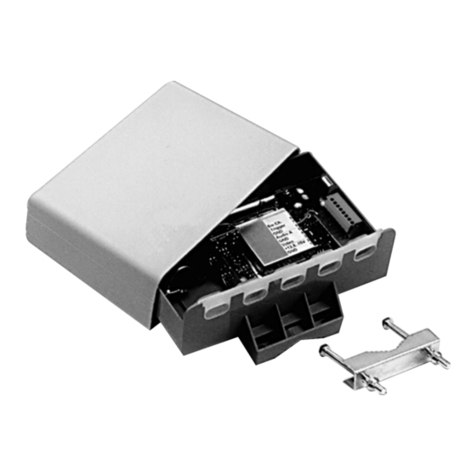
DigitaLinx DL-HDCX User manual

User’s Manual
DigitaLinx™ HDMI™
Coax Transmission System
Part #: DL-HDCX

2Table of Contents
Table Of Contents
Table Of Contents.................................................................................................2
Welcome and Safety Notes...............................................................................3
Product Description and General Specications..................................4-5
Environmental Reliability Specications .....................................................6
Features ...................................................................................................................7
Installation ..........................................................................................................8-9
Mechanical Specications.............................................................................. 10
Technical Specications.................................................................................. 11
Mounting Options ......................................................................................12-13
Warranty Information ...................................................................................... 14
Customer Service .............................................................................................. 15

3
Congratulations on your purchase of a DigitaLinx™ HDMI™ Coax Transmission
System. This manual contains information that will assist you in the installation and
operation of this product. Please inspect the contents of the package to ensure
all required material is present. You will need to provide 2 HDMI cables to connect
your equipment to the transmitter and receiver.
Contents:
Each DigitaLinx™ HDMI™ Coax Transmission System package contains
the following items:
1 each DL-HDCX HDMI™ Coax Transmission System Set (TX unit)
1 each DL-HDCX HDMI™ Coax Transmission System Set (RX unit)
1 each 12 VAC Power Supply (UL) and C(UL) listed Class 2 C(UL)US
1 each Users Manual
Safety Precautions:
1.) Please read all product manuals and safety notes prior to
operating this or any devices.
2.) Retain the product manuals and safety notes for future reference
3.) Unplug this unit prior to cleaning. Use a damp cloth for cleaning.
4.) Do not use this equipment near damp or wet locations.
5.) The product should only be powered by the indicated sources in the
specications. Do not use other sources of power.
6.) Do not use damaged power cords or plugs and do not use loose
electrical outlets. Please refer repair of non-conforming electrical
equipment to certied personnel.
7.) Do not place heavy articles or other equipment on top of this device
or its associated peripherals.
8.) Do not use this device near ammable material, liquids, or gas.
Welcome and Safety Notes
Welcome and Safety Notes

4
This DigitaLinx™ HDMI™ Coax Transmission System is an externally powered digital HDMI
and DVI transmission system to send HDMI and DVI signals over four coaxial cables. The
fth coaxial cable is for 12 VAC power distribution. The device is compliant with DVI 1.0 and
supports HDMI 1.3 high speed signals. The device is fully compliant with HDCP protocol,
CEC (control) and DDC (Monitor Identication). This device uses Gennum’s ActiveConnect™
Technology to transmit HDMI and DVI over long distances at very high data rates.
In addition to new installations requiring long transmission distances at high resolutions,
this HDMI™ Coax Transmission System is ideal for installations where a pre-wire or past
installation has been completed with RGB cable or where space constraints limit installing
HDMI® or DVI cables. The RGB cable solution is also excellent for retrot applications.
Current Analog RGBHV installations can be quickly and easily converted to Digital HDMI™.
The compact design allows the devices to be unobtrusive in the nal installation. It is
recommended to test an application using the customer equipment as the signal from the
source device varies between manufacturers.
The system can easily accommodate DVI only inputs and outputs by using Liberty’s high
quality HDMI to DVI interconnects. The DVI connector is routed to the sources and display
unit while the HDMI connector plugs into the DigitaLinx™ HDMI™ Coax Transmission System.
The digital audio signal is not transmitted when using DVI connectors.
The actual transmission distance can vary depending on many factors. Maximum distances
are a function of resolution, color depth, refresh rate, cable quality and termination quality.
The quality of the RGB cable is a prime factor in limiting distances. The use of Serial
Digital Coaxial cable will extend distances. SDI Coaxial Construction is a 100% bonded
foil shield and a 95% coverage Tinned Copper braid shield with an SRL value greater then
-20dB to 750 MHz. Use of a braid shield only coaxial cable like a closed circuit TV coax is
not recommended due to the transmission of higher frequencies however it will work to
reduced distances.
Product Description and General Specications
Product Description and General Specications
ITEM DESCRIPTION
Model Name DL-HDCX (TX Unit) DL-HDCX (RX Unit)
Input(s) (1) HDMI type A Receptacle (5) BNC Jacks
Output (5) BNC Jacks (1) HDMI type A Receptacle
Supported Resolutions 480i, 480p, 720p, 1080i, 1080p up to 60 Hz
HDCP Compatible Yes
Power Consumption 12 VAC 450mA from supplied Power supply.
Unit can accommodate a wide range 10-32VDC or 10-28VAC or power inputs
Dimensions: 56 x 112 x 16.5 mm (LxWxH) 56 x 112 x 16.5 mm (LxWxH)
(Length xWidth x Height) 2.20”x 4.41”x 0.65” 2.20”x 4.41”x 0.65”
Weight ~0.125 Kg
4.41 ounces
~0.126 Kg
4.41 ounces

5
Product Description and General Specications
Product Description and General Specications (Continued)
This is a practical application chart with actual observed distances and performance in a real
application. Longer distances can be achieved at lower resolutions. Higher resolutions and
color depths will result in shorter distances. Some sources do not adhere to HDMI standards
and may not be transmitted the full expected distance.
Cable Part Number(s) Cable Description 1080p60 w/HDCP
RGB5C-PVC or PLN Mini HiRes 26 AWG stranded 150 feet / 45 meters
RGB5C-25-CM or CMP Mini HiRes 25 AWG solid 175 feet / 53 meters
RGB5C-23-CM MRG59 SDI 23 AWG Solid 300 feet / 90 meters
RGB5C-20-CMR RG59 SDI 20 AWG Solid 400 feet / 122 meters (estimated)
RGB5C RG6 SDI 18 AWG Solid 600 feet / 183 meters (estimated)

6
The DigitaLinx™ HDMI™ Coax Transmission System recommended environmental
operating limits are a temperature range from 10°C to 40°C, non-condensing
humidity levels from 10-80% and an altitude ceiling of 3,000 meters (9,840 feet).
Environmental limits for transportation are established as a temperature range of
-25°C to 60°C, non-condensing humidity levels from 5-95%, and an altitude ceiling
of 15,000 meters (49,200 feet)
Environmental limits for storage are established as a temperature range of -20°C to
45°C, non-condensing humidity levels from 5-95%, and an altitude ceiling of 3,000
meters (9,840 feet)
Environmental Reliability Specications
Environmental Reliability Specications

7
High Quality Picture –
No Loss of Resolution or introduced Digital Artifacts
Our HDMI™ Coax Transmission System is manufactured to deliver the highest
quality picture by preserving the native resolution from the video sources and
eliminating any digital artifacts (pixel loss or “sparklies”). Due to the nature of
digital signals any non-active connector junctions will detrimentally aect the
signal, this device provides active junctions to equalize and amplify the signal
(boosting) and ensures the best signal quality to the display.
No Digital to Analog or Analog to Digital Conversion
This device does not convert the digital HDMI signal to an analog signal. Rather
it takes advantage of the high bandwidth capabilities of a coax cable to transmit
the digital HDMI signal hundreds of feet. HDCP, DDC and CEC signals are also
supported to the full transmission distance of the HDMI signal.
Signal Amplication
Each HDMI™ Coax Transmission System has a safety certied 12 VAC external
power supply to ensure adequate power is available to perform the signal boost
to the correct specication. This is necessary because the introduction of a
HDMI™ Coax Transmission System usually indicates that longer cable lengths are
in use. This device amplies and equalizes the signal from a longer length cable
to the original native shape and signal power. All Liberty Wire & Cable HDMI
interconnects are tested to ensure 1080p resolution.
Compact Design
The HDMI™ Coax Transmission System device is manufactured in a small
convenient form factor which allows the devices to be situated in an unobtrusive
installation. The Five BNC receptacles are oriented 180° from the HDMI connector
to facilitate a straight cable lay.
Wide Range of Power Input
The HDMI™ Coax Transmission System device is manufactured to support the
custom installation market and the device can accommodate a wide range of
input power sources. It can accept DC power from 10-32 volts and AC power from
10-28 volts. Each unit is packaged with a Phoenix style connector for assembly
onto the power supply wires.
Features
Features

8
Installation
Installation
The recommended method for connection of devices to the HDMI™ Coax
Transmission System is listed in the following steps. Please ensure this order is
followed to enjoy the full function of the device.
1.) Ensure the digital video/audio source and display is turned o.
2.) Connect the digital video/audio source to the input port of the DigitaLinx™
HDMI™ Coax Transmission System.
3.) Connect the digital display to the output port of the DigitaLinx™ HDMI™
Coax Transmission System.
4.) Power up the DigitaLinx™ HDMI™ Coax Transmission System. Power LEDs
on both the transmitter and receiver should be illuminated.
5.) Power up the digital display.
6.) Power up the digital video/audio sources
7.) HDCP handshaking operation can take up to 20 seconds.
8.) Check the LED power indicator and status indicators on the DigitaLinx™
HDMI™ Coax Transmission System. The signal indicators should be lit when
the devices are correctly attached. It does not indicate successful data
transmission between the transmitter and receiver. See troubleshooting on
Page 12 if the LED’s are not lit.

9
Installation (Continued)
Installation
Alternative Power Strategies
Note: The unit can function without the fth coaxial cable if power is supplied
to both the TX and RX unit by separate DC power units. Extra Power units are
sold separately under part number DL-HDCX-PS. In addition the power supply
can be connected at either the TX or RX end of the system. If there are only 4 coax
cables available a twisted pair cable can be connected between the green phoenix
power supply connectors to supply power to the TX or RX not directly connected
to the power supply. Make sure that the twisted pair and power supply are
adequate to provide at least the minimum power to the distant device. e.g. A 10
volt power supply and a 24 AWG twisted pair will not be adequate at 200 feet due
to cable losses.
If AC power is used it must be ungrounded (one side of power can not be
connected to the coax shield).

10
Mechanical Specications
Dimensions: DL-HDCX: 2.20” x 4.40”x 0.65” (56 x 112 x 16.5 mm) (LxWxH)
Mechanical Specications
Power Supply Jack: Two pin Phoenix connector (not polarity specic)
Liberty supplied power supply is 12VAC 600mA. Unit can accommodate a wide range
10-32 VDC or 10-28 VAC from alternative power supplies.
PWR LED: Green LED Power Indicator. Both Units require this LED to be functioning.
Clip: Clip to provide strain relief for power supply cable
SOURCE ON LED: Green LED. Indicates Source is Powered up and connected.
DISPLAY ON LED: Amber LED (TX unit) Green LED (RX unit). Indicates the Sink (Display)
is Powered up and connected.
BNC JACK (1-5)
CH 1 – Red (note: signal is not Red this is just a quick guide for standard hook up)
CH 2 – Green (note: signal is not Green this is just a quick guide for standard hook up)
CH 3 – Blue (note: signal is not Blue this is just a quick guide for standard hook up)
CH 4 – White (or Gray) (note: signal is not only clock this is just a quick guide for standard hook up)
Power IN – Yellow (or Black)
SOURCE: HDMI from digital media source DISPLAY: HDMI to digital video display

11
Technical Specications
Frequency Bandwidth: 6.2 Gbps
Supporting Graphic Resolution: 1080p /60 deep color,
or equivalent computer resolution
Transmitter
Input HDMI Type A receptacle 1 port
Output BNC Jack 5 ports
Power 2 pin Phoenix style connector
Receiver
Input BNC Jack 5 ports
Outputs: HDMI Type A receptacle 1 port
Power 2 pin Phoenix style connector
Power Supply: External power from DC Adapter
HDCP (High-bandwidth Digital Content Protection) Compliant
CEC Compliant
DDC Compliant
Technical Specications
Connector Pin Assignment for HDMI Type A Receptacle
Pin # Description
1 TMDS Data 2 +
2 TMDS Data 2 shield
3 TMDS Data 2 -
4 TMDS Data 1 +
5 TMDS Data 1 shield
6 TMDS Data 1 -
7 TMDS Data 0 +
8 TMDS Data 0 shield
9 TMDS Data 0 -
10 TMDS Clock +
11 TMDS Clock shield
12 TMDS Clock -
13 CEC
14 RESERVED
15 SCL
16 DDC DATA
17 DDC/CEC GROUND
18 +5VDC POWER
19 HOT PLUG DETECT

12
Mounting Options
Powered rack mounts in 1, 2, and 3 RU heights are available for switching systems
and HDMI distribution
1 RU Rack Mount
Front View
3 RU Rack Mount
Front View
Mounting Options
Part #: Family Height Capacity
52-111-000 ProSeries 1U 6 single layer full, Basic Block, or ProSeries Bricks.
Or 3 double layer ProSeries Bricks full or half size.
52-121-000 ProSeries 2U 12 single layer full, Basic Block, or ProSeries Bricks.
Or 6 double layer ProSeries Bricks full or half size.
52-131-000 ProSeries 3U 18 single layer full, Basic Block, or ProSeries Bricks.
Or 9 double layer ProSeries Bricks full or half size.

13
52-000-002 Brick Bracket Plate Plate, 2 Screws
A manufactured steel plate to provide lateral ears is another mounting option.
Ears:
3 RU Rack Mount
Rear View
Mounting Options
1 RU Rack Mount
Front View
3 RU Rack Mount
Front View
Mounting Options

14
Warranty Information
1 (One) Year Warranty
Liberty Wire & Cable warrants this DigitaLinx™ HDMI™ Coax Transmission System to
be free from defects in workmanship and materials, under normal use and service,
for a period of one (1) year from the date of purchase from Liberty Wire & Cable or
its authorized resellers.
If a product does not work as warranted during the applicable warranty period,
Liberty Wire & Cable shall, at its option and expense, repair the defective product or
part, deliver to the customer an equivalent product or part to replace the defective
item, or refund the customer the purchase price paid for the defective product.
All products that are replaced will become the property of Liberty Wire & Cable.
Replacement products may be new or reconditioned.
Any replaced or repaired product or part has a ninety (90) day warranty or the
remainder of the initial warranty period, whichever is longer.
Liberty Wire & Cable shall not be responsible for any software, rmware,
information, or memory data loss of customer contained in, stored on, or
integrated with any products returned to Liberty Wire & Cable for repair under
warranty or not.
Warranty Limitation and Exclusion
Liberty Wire & Cable shall have no further obligation under the foregoing limited
warranty if the product has been damaged due to abuse, misuse, neglect, accident,
unusual physical or electrical stress, unauthorized modications, tampering,
alterations, or service other than by Liberty Wire & Cable or its authorized agents,
causes other than from ordinary use of failure to properly use the product in the
application for which said product is intended.
Warranty information

15
Troubleshooting/Customer Service
Customer Service
Troubleshooting
Liberty Wire and Cable
11675 Ridgeline Drive
Colorado Springs, CO 80921
If you have issues, questions, or require assistance with the use of this device please
contact Liberty Wire and Cable with any of the following contact points:
The DigitaLinx™ HDMI™ Coax Transmission System is designed for years of
trouble free service, please reference the troubleshooting steps below if you are
having diculties.
Recommendation:
Due to variations in the implementation of the HDMI standard by manufacturers
of source and display equipment, it is highly recommended that any system be
mocked up and tested with appropriate cable lengths prior to installation. There
are many compatibility issues with HDMI equipment that become more apparent
as cable extenders are added to the equation. This system goes to great lengths to
minimize those problems. However, after wire is installed, the walls nished and
the display is hung, it’s a little late to nd that the source isn’t compatible with the
switching equipment, transmission equipment and the display.
− All cables must be properly connected for any signal to be transmitted.
− If no image is displayed, conrm that all coax cables are properly connected, red to red, green to green etc.
− If there is still no image, conrm that all cable are continuous and not shorted between the center
conductor and the shield.
− Some VGA cables use a twisted pair for the H andV signals. This device requires a coax cable for channels 1-4.
− Cables should be similar in length and of the same part number and manufacturer. CATV/MATV style cables
with Copper Clad Steel conductors and Aluminum braid shields are not recommended.
− Signals on these cables are bi-directional so the coax signals will not function if connected to intermediate
electronics (such as an RGBHV switcher).
− If the system does not function try lower resolutions from the source
− All LEDs will be on with a properly connected system. All LEDs being on does not indicate a properly
connected system.
− TheYellow power channel can be used to determine if the cables are properly constructed. Disconnect all
Coax cables. One at a time connect each cable to the yellow BNC connector with the power supply connected.
If the Power LED on the unit not connected to the power supply illuminates, the cable is not open, nor does it
have a short. Return it to its proper connectors beginning at end that has the power supply.
Phone: (800) 530-8998 and ask for
technical assistance.
Email: Sales@libertycable.com and indicate
in Subject Line “Technical Assistance”

© 2009 Liberty Wire & Cable. All Rights Reserved.
Liberty Wire & Cable
11675 Ridgeline Drive
Colorado Springs, CO 80921
800-530-8998
www.libertycable.com
Table of contents
