Digitron EX-9486-W User manual

EX-9486-W
Serial to WI-FI Converter
Operation Manual
First Edition, Oct 2007

1
Table of Contents
1. Introduction ………………………………………………… 3
Overview ………………………………………………… 4
Package Check List ………………………………………… 5
Product Features …………………………………………… 6
Hardware Specifications …………………………………… 8
2. Converter Description ……………………………………… 11
Product Panel Views ……………………………………… 11
Top Side …………………………………………………… 11
Right Side ………………………………………………… 12
Left Side …………………………………………………… 13
Rear Side ………………………………………………… 13
LED Indicators …………………………………………… 14
Wiring Architecture ……………………………………… 15
RS-232 …………………………………………………… 15
RS-422/RS-485 …………………………………………… 15
3. EX-9486-W Configuration ……………… 16
Software Setup and Initial IP Configuration …………… 16
EXTool Software Setup ……………………………… 17
EXTool Setup …………………………………… 17
Serial to Wi-Fi Configuration ……………………………… 19
Broadcast ……………………………………………………… 19
Device List …………………………………………………… 20
General ………………………………………… 20
Security ………………………………………… 21
Networking ……………………………………… 22
Wireless ………………………………… 22
Notification ……………………………………………… 23

2
Management …………………………………………… 23
Upgrade Firmware ……………………………… 24
Save/Load ………………………………………… 24
Port ………………………………………… 26
Serial Settings ………………………………………… 26
Service Mode ………………………………………… 27
Notification ……………………………………… 28
VCOM List ……………………………………… 30
Setup Wizard ……………………………… 31
Virtual Com Wizard ……………………………………… 31
Serial Tunnel Wizard ……………………………………… 33
Group IP Wizard ……………………………………… 34
Group Setup Wizard ……………………………………… 35
Group Firmware Wizard ……………………………… 37
IP Collection ……………………………………… 38
System Log ……………………………… 39
4. Web Console Configuration ……………… 40
Appendix A - FAQ ………………………………………… 38
Appendix B - Pin Outs and Cable Wiring ………… 39
DC Power Outlet ………………………………………… 39
RJ-45 Pin Assignment …………………………………… 39
RS-232 Pin Assignment ………………………………… 39
RS-232 Wiring Diagram ………………………………… 40
RS-422 Pin Assignment ………………………………… 40
RS-422 Wiring Diagram ………………………………… 40
RS-485 Wiring Diagram ………………………………… 40

3
1
1
Introduction
Serial-Server is providing new ways of connecting legacy serial converter devices to
a Local Area Network (LAN) or Wide Area Network (WAN). EX-9486-W is designed
to operate serial ports through wireless(Wi-Fi 802.11b & g) or entity line(RJ-45 cable)
over 100Mbit/s Ethernet networks. The data is transmitted via TCP/IP protocol.
Therefore control is available via Ethernet, Intranet and Internet. EX-9486-W is
packaged in a case well suited for industrial environments. All serial ports operate in
common RS-232 mode , industrial RS-422 and RS-485 modes configuration.
EX-9486-W is a low-cost, high performance design. By careful selecting high quality
with competitive prices components in the world, products made network
connectivity possible with affordable cost for virtually all kinds of devices.
The EX-9486-W can connect the Remote I/O Control module of EX9000 Series for
EX9000 Series to Wireless by RS-232/422/485. This operation manual will guide you
step by step for the various functions of the EX-9486-W.
The following topics are covered in this chapter:
Overview
Package Checklist
Block Diagram
Product Features
Product Specifications

4
Overview
EX-9486-W(ARM-9/200MHz SRAM/16MB FlashROM/8MB) is provide a
perfect solution to make your industrial serial devices Internet ready instantly
via wireless LAN. ARM-9 Series of EX-9486-W makes them the ideal choice
for connecting your RS-232 or RS-422/485 serial devices—such as PLCs/
meters/EX-9000 Series—to an IP-based Wi-Fi Ethernet LAN, making it
possible for your software to access serial devices anywhere and anytime over
a wireless local LAN or the Internet.
ARM-9 Series of EX-9486-W ensures the compatibility of network software that
uses a standard network API (Winsock or BSD Sockets) by providing TCP
Server Mode, TCP Client Mode, and UDP Mode. And thanks to ARM-9 Series’
Real COM/TTY drivers, software that works with COM/TTY ports can be set up
to work over a TCP/IP network in no time. This excellent feature preserves
your software investment and lets you enjoy the benefits of networking your
serial devices instantly.
ARM-9 Series of EX-9486-W support manual configuration via the handy web
browser console and many protocols including TCP, IP, UDP, HTTP, DHCP,
ICMP, and ARP. They are the best solution to network your serial devices.

5
Package Check List
EX-9486-W product is shipped with the following items:
□
□
□1 unit of EX-9486-W
□
□
□1 unit of Power Adaptor (12V DC, 1.2A)
□
□
□2 unit of dipole antenna(2.0dBi / 5.0dBi)
□
□
□Documentation & Software CD
□
□
□Quick Installation Guide
NOTE: Notify your sales representative if any of the above items is missing or
damaged.

6
Product Features
Data Conversion between RS-232/422/485 and Ethernet
Convert serial device (RS-232, RS-422, RS-485) data/signal into the
TCP/IP package data/signal and send them out with the Ethernet
DataStream; or convert the TCP/IP package data/signal into serial device
data/signal.
Wi-Fi Wireless Ethernet
It based on the latest industry standard Wi-Fi Certified IEEE 802.11g
specification; it offers maximum channel speeds of up to 54 Mbps. The
Wi-Fi function maintains interoperability within the 2.4 GHz frequency band,
offering full compatibility with 802.11b networks. This integrated wireless
solution of EX-9486-W is widely deployed in business environments and is
the standard for wireless access in public places. It also supports key
security features like Wi-Fi Protected Access (WPA), WEP and 802.1x.
Dynamic IP Configuration
Support DHCP client mode, simplifying network address configuration and
management.
Dual LAN Speed
Support 10/100 Mbps Ethernet, auto-detected.
Server / Client Dual Modes
Series can be configured as network server or network client. In the client
mode, it can be installed in network which is protected by NAT router or
firewall, without the need of a real IP address.

7
Web-based Setup
Parameters setup is based on HTTP protocol by using standard browsers
(IE and Netscape). No special software would be required.
Built-in Security Control
Protected by both setup password and access password to prevent
intruders.
Remote updated
Firmware can be reprogrammed directly via Ethernet network to keep up
with latest network standards.

8
Hardware Specifications
WLAN
1. Port Type : RJ-45 ConnectorStandard Compliance: IEEE 802.11b/g
2. Spread Spectrum Technology: DSSS, OFDM
3. Tx Power 11b: Maximum 20 dBm
4. Tx Power 11g: Maximum 18 dBm
5. Rx Sensitivity: -70 dBm @ 54 Mbps, -85 dBm @ 11Mbps
6. Transmission Rate: 54 Mbps (max.) with auto fallback (54,48, 36, 24, 18,
12, 11, 9, 6, 5.5, 2, 1 Mbps)
7. Transmission distance: Up to 300 meters(@12 Mbps, in open areas)
8. Security: WEP 64-bit/128-bit data encryption, AES, WPA2
9. Antenna Connector: Reverse SMA
10. Network Mode: Infrastructure, Ad-Hoc
LAN for configuration / Ethernet hub
1. Ethernet: 10/100 Mbps, RJ45
2. Protection: Built-in 1.5 KV magnetic isolation
Serial Communication Parameters
1. No. of ports : 1 RS-232/422/485 port, male DB9, S/W selectable
2. RS-232 Signals : TxD, RxD, RTS, CTS, DTR, DSR, DCD, GND
3. RS-422 Signal : Tx+ , Tx- , Rx+ , Rx –
4. RS-485 Signal : Data+ , Data-
5. Serial Line Protection : 15 KV ESD for all signals
Beeper for event warning or unit positioning ( Optional)

9
Serial Communication Parameters
1. Parity: None, Even, Odd, Space, Mark
2. Data bits: 5, 6, 7, 8
3. Stop bits: 1, 1.5, 2
4. Flow control: RTS/CTS, XON/XOFF
5. Speed: 110 bps to 460.8+ Kbps
Power Requirements & Consumption
1. Power Input : 9 -12 VDC/500mA -1.2A
2. Power Line protection :
1 KV Burst (EFT), EN61000-4-4
0.5 KV Surge, EN61000-4-5
Environmental
1. Operating Temperature : -10 to 70°C (32 to 131°F), 5 to 95% RH
2. Storage Temperature : -20 to 85°C (-4 to 185°F), 5 to 95%RH
3. Regulatory Approvals
RoHS
EMC: FCC Class A, CE Class A
Safety: UL, CUL, TÜV
Class I, DIV II
Software Features
1. Protocols : ICMP, IP, TCP, UDP, DHCP, BootP, ARP / RARP, Telnet,
RTelnet, DNS, SNMP MIB II, HTTP, SMTP, SNTP
2. Serial mode : Virtual Com / TCP Server / TCP Client / UDP / Serial
Tunnel with advanced settings of
TCP Alive Check Timeout
Inactivity Timeout
Delimiter for Data Packing
Force TX Timeout for Data Packing

10
4 Hosts simultaneous connection : Virtual Com / TCP server / TCP Client
(only raw data)
1. Modbus support: (optional software)
2. PPPOE, DDNS : (optional software)
3. Security: HTTPS, SSH v2
4. Event notification by email / SNMP trap
SNMP Trap
Cold/Warm Start
DSR, DCD Changed
IP Changed
Authentication Fail
SNMP Response
System MIB,
Interface MIB,
ICMP, IP, TCP MIB
UDP MIB
RS-232 MIB
5. Utilities : Windows NT/2000/XP/2003/VISTA
Device discovery
Auto IP report
Device setting (run-time change, no rebooting)
Access control list
Group setting
Device monitoring
Serial port monitoring
Log info
Group Firmware update batch
●Virtual COM/TTY Drivers (WDM mode, configuration in windows device manager) : Windows
NT/2000/XP/2003, VISTA
11
2
2
Converter Description
Product Panel Views
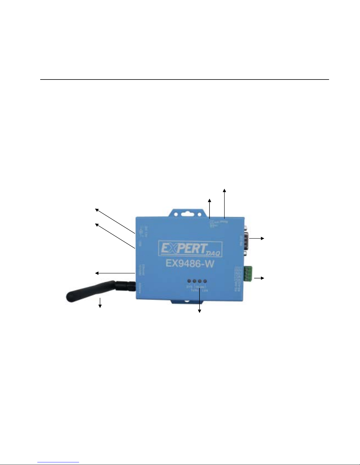
Top Side
LAN RJ-45
DC-In
Power Outlet
Serial I/O Port
RS-232
Serial I/O Port
RS-485/RS-422
Reset Button
Terminator
LED Indicators
USB Port
Antenna

12
Right Side
DC-In Power Outlet
The EX-9486-W is powered by a single 9∼12V DC(Inner positive/outer
negative) power supply and 500~1200mA of current. A suitable power
supply adapter is part of the packaging. Connect the power line to the power
outlet at the right side of EX-9486-W and put the adapter into the socket. If
the power is properly supplied, the “SYS” green color LED will be on
USB Port
The EX-9486-W of USB port is.
Antenna Connector
The connector for antenna is a standard SMA jack. Simply connect it to a
2.0dBi or 5.0dBi dipole antenna (Standard Rubber Duck) and it is 50 Ohms
impedance and can support 2.4GHz frequency.
Ethernet Port
The connector for network is the usual RJ45. Simply connect it to your
network switch or Hub. When the connection is made, the LAN LED
indicator will light. When data traffic occurs on the network, red (Rx/Tx)
indicator will blink during data transferring and receiving.
Ethernet Port
DC-In
Power Outlet
USB Port Antenna
13
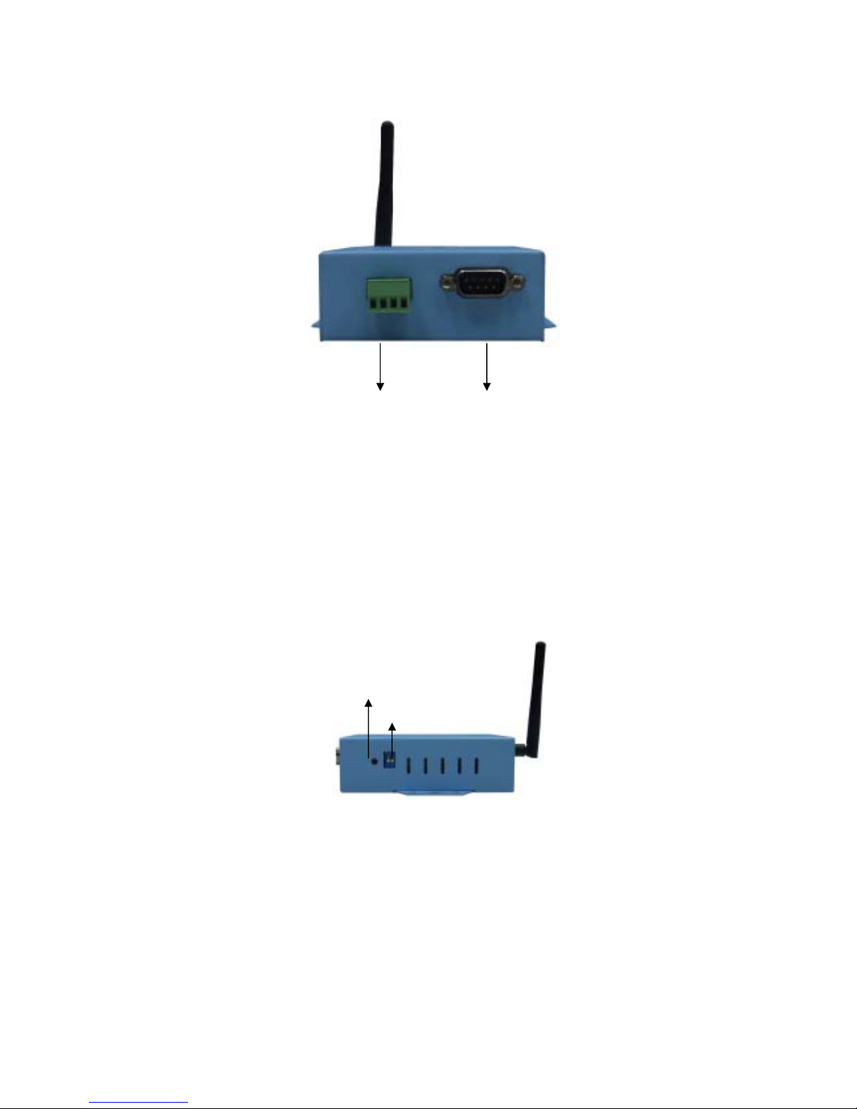
Left Side
Serial I/O Port of RS-232/RS-422/RS-485
Connect the serial data cable between the Wi-Fi converter and the serial
device. Follow the parameter setup procedures to configure the converter
(see the following chapters ).
Rear Side
Reset Button
If by any chance, you forget the setup password, or have incorrect
settings making EX-9486-W TCP/IP converter inoperable. First, turn off
the power. Second, use any point tip to push this button and hold it to turn
on the power at the same time for 5 second. All the parameters will be
reset to the factory default.
RS-485/RS-422 RS-232
Reset Button
Terminator

14
Terminator
The purpose is for compensating signal attenuation in long distance
connection at RS-485/RS-422 I/O. If the switch 1 & 2 are set in “ON”
position, the signal compensation will be activated. To disable the function,
just push switch 1 & 2 to opposite position.
LED Indicators?
SYS (Red):
Power indicator (When the power is on, the LED will blink once per second.)
LAN (Green):
Network signal indicator (When the LAN signal is detected, the LED will be
on.)
TX (Red):
Data sent indicator (When data are sent out to the network, the LED will be
on.)
RX (Green):
Data received indicator (When data are received from the network, the LED
will be on.)

15
Wiring Architecture
RS-232 Wiring Architecture
RS-422/RS-485 Wiring Architecture
When you finish the steps mentioned above and the LED indicators are as shown,
the converter is installed correctly. You can use the Software Setup CD to setup
the IP Address.
To proceed the advanced parameter setup, please use a web browser (IE or
Netscape) to continue the detailed settings.

16
3
3
EX-9486-W Configuration
Software Setup and Initial IP Configuration
When setting up your converter for the first time, the first thing you should do is
configure the IP address. This chapter introduces the method how to install the
program and how to configure the EX-9486-W device’s IP address.
For quick and easy start , We suggest you to reference “Quick Installation
Guide” manual.
The following topics are covered in this chapter:
EXTool Software Setup
EX-9486-W Configuration
Converter Configuration through Web

17
EXTool Software Setup
On PC we provide a Device Management Utility named EXTool which is an
executable program in Windows 32 bit environments. EXTool Setup is used
to detect and setup the installed converter. It uses UDP broadcast packets to
query and configure converters on the network.
EXTool Setup
Insert the CD and select “EXTool_ODM_Setup”,folder and double click
“EXTool_ODM_Setup.exe”, runing to install Windows utility.
When the “installing EXTool” screen is pop-up then double click the “Start”
icon for installing.

18
1.1 After finishing installation, the “installation was completed
successfully” screen will be pop-up and jus double click the “OK” icon.
1.2 Coming the screen is for choosing to run “Launch EXTool Now” or
“Launch EXTool Later”
1.3 If you choice the item of “Launch EXTool Now” then the EXTool of
Device Configuration manual screen will be pop-up.

19
EX-9486-W Configuration
Broadcast
After finishing EXTool installation and lunch the EXTool, you can
double click the “Broadcast” button at left side upper corner. It will
detect the existence of the installed converters on the network.
Select the converters you wish to add and double click “Add” button.
The table will depict the converters’ status such as IP address, MAC
Address, Device Name and status.
Device List
In the Device List icon, you will find the added converter in the list and
double click on the device will continue to configure other rest of the
converter settings.
Table of contents
Popular Media Converter manuals by other brands

madVR Labs
madVR Labs Envy Sony Setup Guide

Lika
Lika ROTAPLUS I28 Series quick start guide

TR-Electronic
TR-Electronic CMS582M-4096/4096 IOL DMS 14H7 KRF Assembly instructions

Linear Technology
Linear Technology DC1523A Demo Manual

Delta Electronics
Delta Electronics PMT V Series instruction manual

SPROLINK
SPROLINK VA1 user manual


