Digitus professional DN-80112 User manual

16/24-Port Gigabit
Desktop Switch
Manual
DN-80112 DN-80113
Introduction
The DN-80112/DN-80113 is an Unmanaged Gigabit Ethernet rack-mount switch that
provides wire connection. It provides Gigabit Ethernet switching function, which
allows high-performance and backward compatible to all speed connections,
10Mbps, 100Mbps and 1000Mbps Ethernet networks. The Ethernet Switch delivers
all the advantages of a switching hub in a standard 1U size of metal enclosure and it
is ideal for any enterprise office or data server room. There are special rubber feet
and rack-mount kit accessory included for user’s convenience.
This switch provides 16 or 24 auto-sensing 10/100/1000Mbps Ethernet RJ-45 ports
which automatically detect the speed of the devices that you plug into them. This
switching function allows 10Mbps, 100Mbps, and 1000Mbps Full/Half-duplex devices
to communicate on the same network without having to replace any infrastructure.
This flexible feature allows your network a timely, economical migration to
1000Mbps Gigabit Ethernet.

Key Features
Conforms to IEEE802.3, 802.3u, 802.3x, 802.3ab
Automatic MDI/MDIX crossover for all ports
N-Way Auto-negotiation for 10/100/1000Mbps transmissions
1U, 19” Rack mountable
Store-and-Forward switching architecture
Auto-detection of full/half-duplex mode in all ports
Plug-and-Play configuration auto address learning
LED indicators for Power, Link/activity
Package Contents
Ethernet Switch
AC power cord
User’s manual
Four (4) adhesive-backed rubber feet
Two (2) rack-mount pallet and Six (6) screws
IMPORTANT: If any piece is missing or damaged, please contact your local dealer or
reseller for service.
Product Specifications
DN-80112 (16-Port 10/100/1000Base-TX Gigabit Ethernet Switch)
Ports: 16-Port 10/100/1000Base-TX
MAC Address: 8K Mac address table
Jumbo Frame: 9KB
LED Indicator: Per port: Link/Activity
Per unit: Power
Dimension: 440mm x 200mm x 44mm (W x D x H)
Operating Temp: 0°C to 40°C
Operating Humidity: 10% to 90% (Non-condensing)
Power Consumption: 15 Watt @ AC 240V/60Hz (Maximum)
EMI: CE Class A
DN-80113 (24-Port 10/100/1000Base-TX Gigabit Ethernet Switch)
Ports: 24-Port 10/100/1000Base-TX
MAC Address: 8K Mac address table
Jumbo Frame: 9KB
LED Indicator: Per port: Link/Activity
Per unit: Power
Dimension: 440mm x 200mm x 44mm (W x D x H)
Operating Temp: 0°C to 40°C
Operating Humidity: 10% to 90% (Non-condensing)
Power Consumption: 20 Watt @ AC 240V/60Hz (Maximum)
EMI: CE Class A
Hardware Description
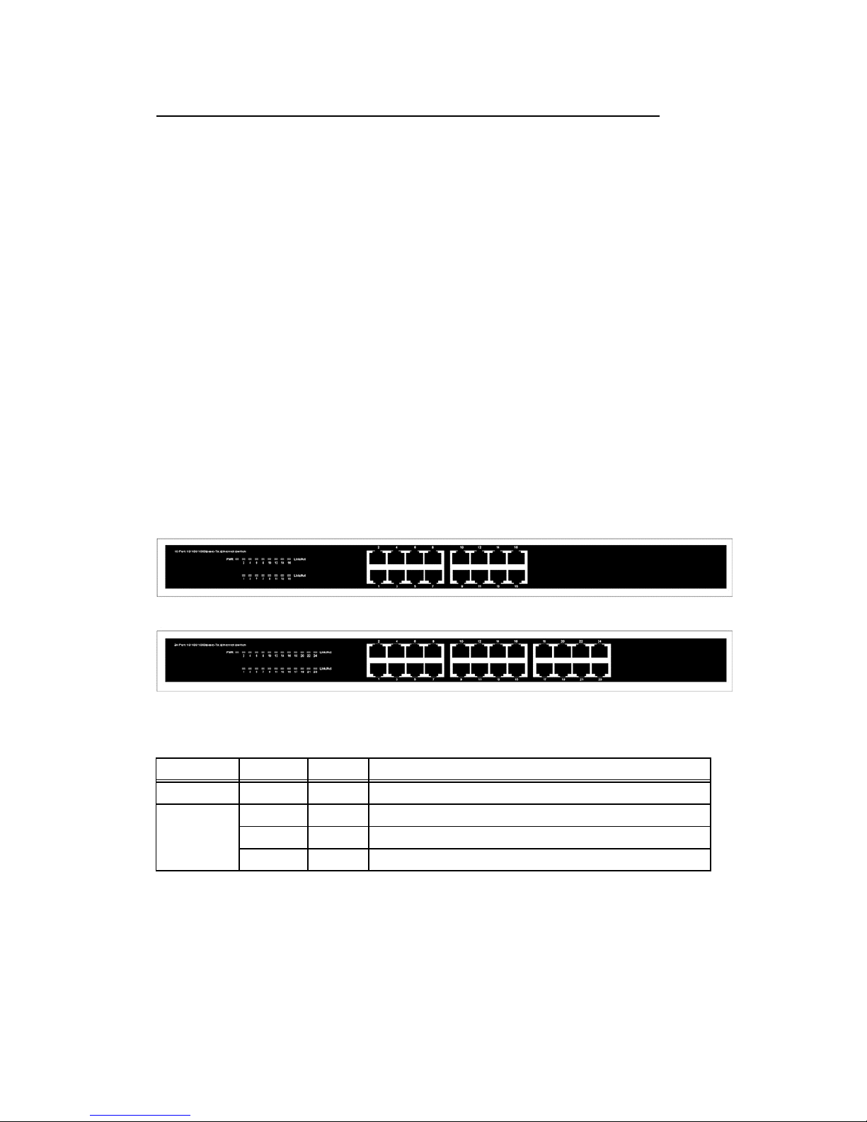
The Front Panel
The front panel consists of LED Indications and 16/24 auto-sensing ports.
LED Indicators
Per Device: Power
Per Port: LINK/ACT (Link/Activity)
Figure 2. Front panel view of LED indications
LED Status Color Description
Power On Green The switch is supplied with suitable power.
LINK/ACT
On Green The port is connecting.
Blinks - The port is receiving or transmitting data
Off - The port is not linked successfully with the device.
RJ-45 Ports (Auto MDI/MDIX)
Auto-sensing ports of 10/100/1000 N-way for 10/100/1000-TX connections. In
general, MDI means connecting to another Hub or Switch while MDIX means
connecting to a workstation or PC. Therefore, Auto MDI/MDIX means that you can
connect to another Switch or workstation without changing pin-to-pin or crossover
cabling.
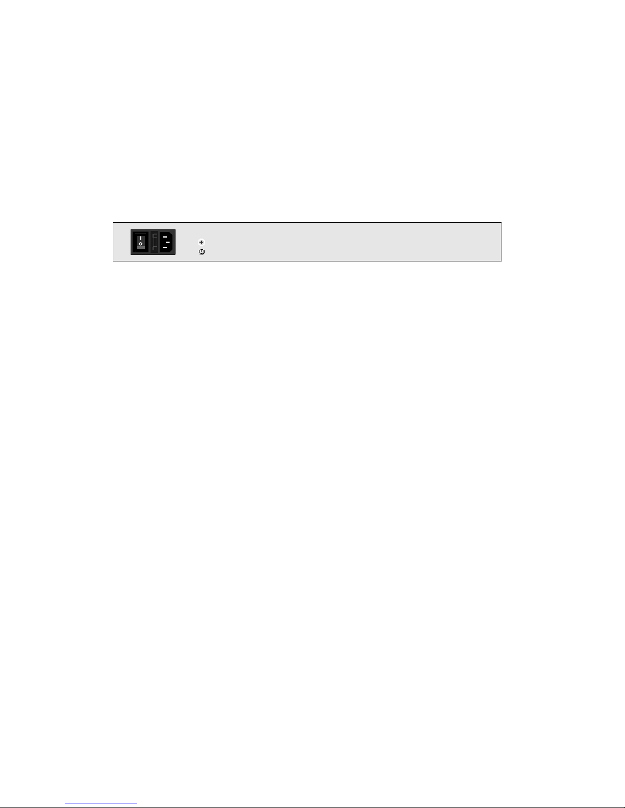
The Real Panel
The rear panel view of the Ethernet switch consists of an AC power connector.
Figure 3. Rear panel view of the switch
AC Power Connector
Plug the female connector into the switch and male connector into a power outlet.
Supports input voltages 100-240VAC, 50/60Hz.
Troubleshooting
The Switch can be easily monitored through panel indicators to assist in identifying
problems. This section describes common problems you may encounter and possible
solutions.
Power
If the power indicator does not light when the power cord is plugged in, you may
have a problem with the power outlet or cord. However, if the power LED goes off
after running for a while, check for loose power connections, power losses or surges
at the power outlet. Turn off power, wait 30 seconds and turn power on again. If
problem is still not resolved call for dealer’s assistance
Diagnosing LED Indicators
If link indicator does not light after making a connection, check whether network
interface (e.g., a network adapter card on the attached device), network cable, or
switch port is defective. Be sure the cable is plugged into both the switch and
corresponding device. Verify the proper cable type is used and its length does not
exceed specified limits.

Cabling
Verify that the cabling type is correct. Make sure all cable connectors are securely
seated in the required ports. Use only standard Unshielded Twisted-Pair (UTP),
Category 3, 4, 5, or 5e cables. Use only Category 5 or 5e when connecting with Fast
Ethernet. Make certain the maximum distance between the Switch and what it’s
connected to is 100 meters or less.
NOTE: Do not plug a standard telephone cord into an RJ-45 port. This may damage
the switch
Hereby ASSMANN Electronic GmbH, declares that this device is in compliance with the
requirements of Directive 2014/30/EU (EMC), Directive 2014/35/EU (LVD) and the Directive
2011/65/EU for RoHS compliance. The complete declaration of conformity can be requested
by post under the below mentioned manufacturer address.
Note:
If wrongly installed or improperly used in the living area, the device can cause interference in
radios and other electronic devices. Appropriate use is when the device, as far as feasible, is
operated with shielded connection cables (with network products in addition to category 5
shielded cables and higher). The device has been tested and falls within the limits of class A
computing equipment according to the requirements of EN 55032.
Warning:
This device conforms with test category A - it can cause radio interference in the living area; in
this case the operator may demand that appropriate measures are implemented and arise for
this reason. Declaration of conformity: The device fulfills the EMV requirements according to
EN 55032 for ITE and EN 55024 class A. In this way, the fundamental protection requirements
of the EMV-2014/30/EU guideline are fulfilled.
www.assmann.com
Assmann Electronic GmbH
Auf dem Schüffel 3
58513 Lüdenscheid
Germany
This manual suits for next models
1
Table of contents
Popular Network Router manuals by other brands


Mellanox Technologies
Mellanox Technologies PowerEdge M420 user manual

Hirschmann
Hirschmann MACH104-20TX-FR Series user manual

Alcatel
Alcatel SpeedTouch 610 Orientation guide

Intel
Intel Express 8205 quick start guide

Medium Link
Medium Link MLS-200-C user guide

Unitronics
Unitronics UCR-ST-B8 installation guide


