Dimac R30 User manual
❖Accessories of Installation
Bracket for machine
Electrical cable ⑤
Emergency cable
Air hose ④
Air regulator
Bolts
①for the bracket
②for the machine
③pass line adjusting ②
④Bonding ①
Mark tube, Terminal ③
Sticker
Air connector
⑤Apron plate
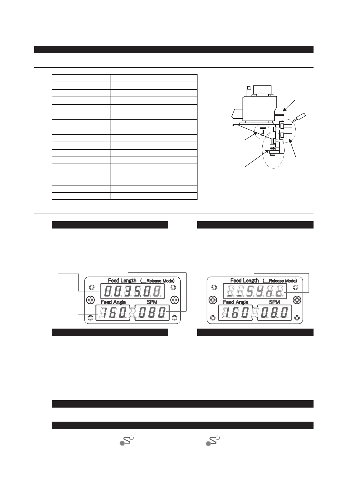
❖Setting Items
Feed Length, Feed Angle, SPM Release Mode
Changeable main screen in "Set" state.
Feed length Release Mode
Setting method of table screen Setting method of "Release Mode"
①Power ①Power
② ← → Setting items can be changed.
③ + / - The value can be Changed.
③ + / - The value can be Changed.
After setting
Synchronous operation
Model
R30 R40 R50
Installation Manual
To display "Release Mode", push on "Sync
Release" switch in "Set" state.
Turn ON "Power switch"
"Release Mode" is not displayed in "Set" state.
Exclusive type
Feed
Angle
R30, R40, R50
Exclusive type
P6:8M
8M
2-M6*12
4-M14*30
8*5:6M
With air filter
Numeric value that can be changed item or
number will be blink.
② First, push on "Sync Release" switch, keep
it.
When "Sync Release" is turned off, the
display returns the main screen.
Press rotation speed
DIMAC
Net 4ml
4-M8*25
1-M12*120
1-3/8B, 2-2/8B
Numeric value that can be changed item or
number will be blink.
If you need to continue inputting, repeat
②,③.
Turn ON "Power switch"
Assortment
Signal(Feed/Release), Scale for
pass line (on the plate)
Description of good
Fixture for the air regulator
⑤
Sync Feed
Sync Release
Press the both switches of Sync-
Feed, -Release switches, then the
feeder will be able to operate
automatically.
④
Set ⇔ Run
Push "Set ⇔ Run" switch, when "Run" lamp is lit, the setting
finishes.
1
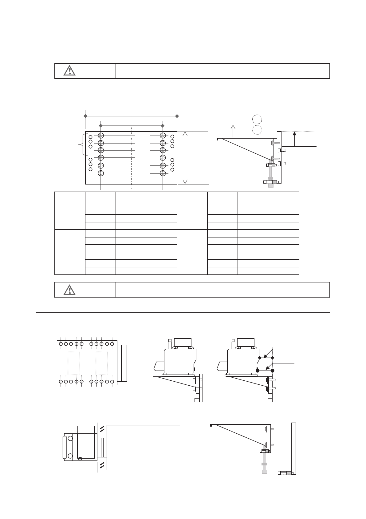
❖R30, R40, R50 Pass line
The pass line height is decided by combination a plate and a holder.
It is necessary to tighten 4 points with a bolt to fix the holder on the plate.
The plate has 4 bolts. The plate thickness: 22mm
Plate Holder
From top 20
A,B,C 30
30
30 250
30
30
Plate Hole Plate Hole
height position height position
A A
B B
C C
A A
B B
C C
A A
B B
C C
❖Mounting position
Main machine-Mounting position: 5
5 4 3 2 1 5 4 3 2 1 Using No.1 Using No.5
85
117
5 4 3 2 1 5 4 3 2 1
❖Confirmation of balance ❖Assembly drawing of the bracket
210~265
190~245
260~315
220~275
240~295
h=0
h=30
h=60
h=90
h=120
h=150
130~185
170~225
150~205
140~195
110~165
120~175
100~155
90~145
70~125
Bolster
h(mm)
95
CAUTION
The plate-center equals the feeding rolls -center.
Bolster
Pass line (mm)
Pass line (mm)
350
200
200~255
180~235
160~215
CAUTION
In case of the pass line over 285mm, Need to add processing holes for fixing bolts.
230~285
2
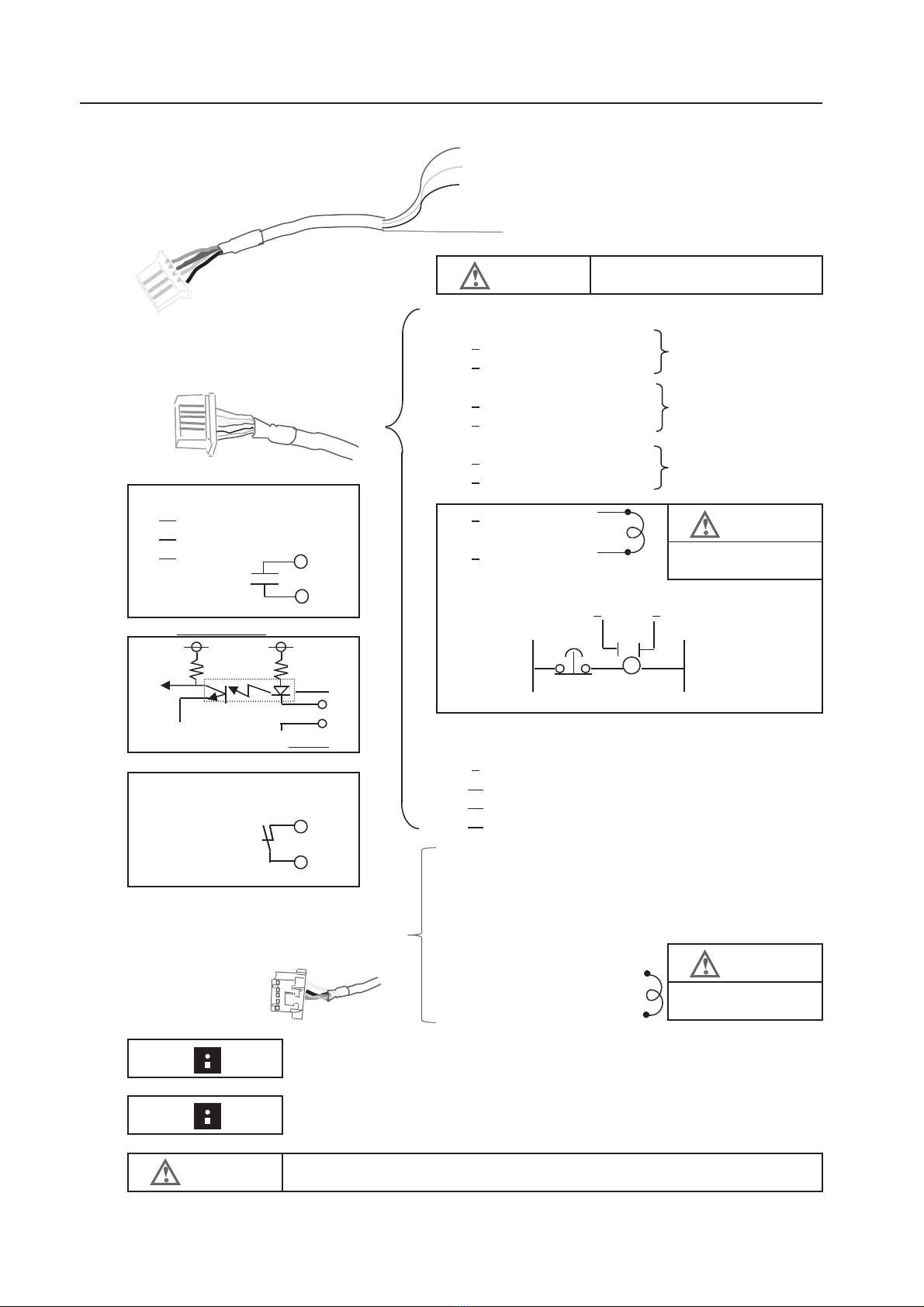
❖Wiring
Red R(200V 50/60Hz)
PC-A Power cable White S(200V 50/60Hz)
0.75mm2Black T(200V 50/60Hz)
Not wiring when single phase
Green/Yellow E(Earth)
1
PC-B Signal cable 2
0.5mm2Option
3
4
5
6
Wire #
1:2 1A at AC 250V or less 7
3:4 1A at DC 30V or less
5:6 8 24V GND
Example for circuit
78
Wire # 7:8 9:10 11:12 S5:S6 0V EMG 100V
5V 24V
R
CPU
7,9,11 ,S5
5V GND
8,10,12, S6
9 Feed input
Wire # 1A at AC 250V or less 10 24V GND
S1:S2 1A at DC 30V or less 11 Release input
S3:S4 12 24V GND
S1
S2
S3
PC-C S4
0.5mm2
S5
S6 Blown:24V GND
White:Emergency stop
To Emergency stop circuit
Emergency and press
processing select
Need to short the circuit of press processing select(S5, S6), if you don't use the
circuit.
DANGER
To cover each cable which is not using connection.
Green:Emergency stop
To Emergency stop circuit
Black:Emergency stop
Red:Emergency stop
Need to wire the release signal, Otherwise Not available in continuous feeding
because of checking the movement of the press using two cam signals.
CAUTION
Yellow:Press cont.
processing
Need to short, if not
using.
You can select which 3 phase or single phase. If it's single phase, you don't have to connect the black wire.
Press cam signal
DANGER
Connect to the primary side
Drive stop signal output
To the stop continuous
on the press circuit
Work shortage sensor
output
Input stop
of Feeder
Press cam signal
CAUTION
To the stop continuous
on the press circuit
Continuous stop signal
output
To the stop continuous
on the press circuit
Need to short, if not
using.
3
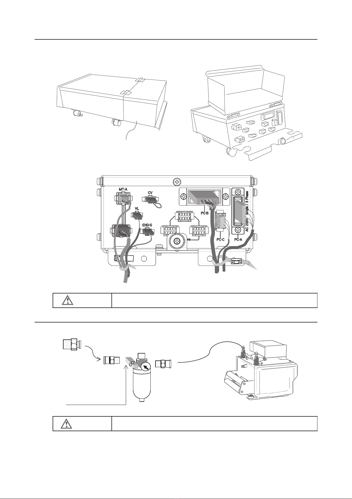
❖Cable connecting
The receptacles of PC-A, PC-B, PC-C are placed inside the connecting cover.
Connecting cover
❖Air piping
3/8B To Air connector
2/8B
*Approximate air pressure : 0.3~0.5 MPa
*Maximum air pressure: 0.5 MPa
CAUTION
2/8B
DANGER
Need to fix three external cables in prepared nylon band.
Air passes in specific
direction
4
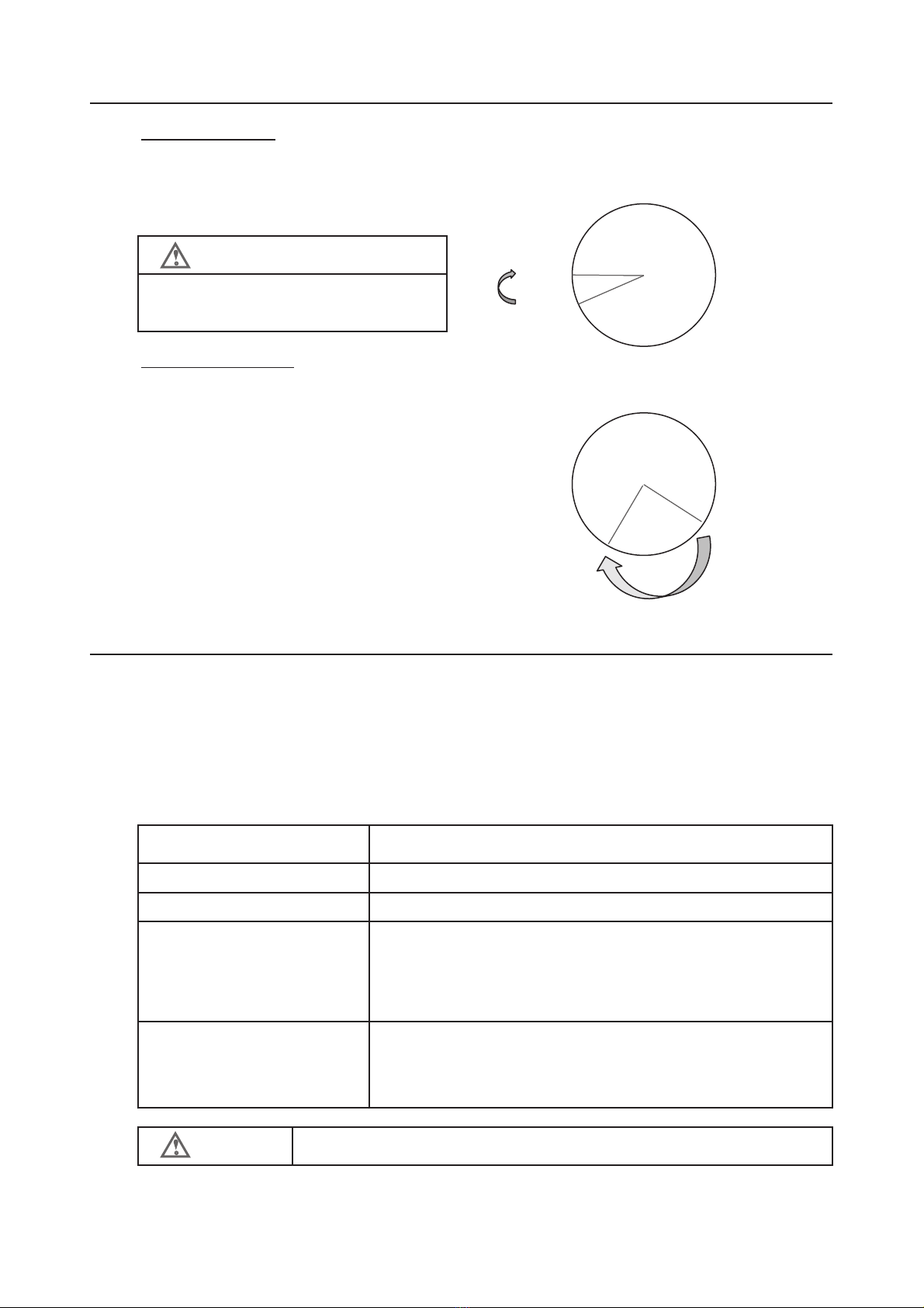
❖Adjusting Press cam signals
Feed signal adjusting
Set the feed start position to feed signal OFF position. Press cam signal
When you make the feed starts on 270°, 0°
Set the ON angle of feed to 240°, and set the OFF angle to 270°
270° 90°
ON
240°
Release signal adjusting 180°
0°
When the release angle is assumed to 200°from 200°, 60°
you turn on the press cam signal in 110 degrees,
and turn off in 200 degrees. 270° 90°
110°
200°
180°
❖Release setting in the controller 【 (_Release Mode) 】
【 (_Release Mode) 】 the display is the back screen of 【 Feed Length 】.
Release Mode is not displayed in "Set" state only.
To display " Release Mode", Push on "Sync Release" switch in "Set" state.
To change the "Release Mode", Keep "Sync Release" switch ON, and using "+" or "-" switch,
You can change the release mode.
Display and contents
Invalid the release signal, Release off state.
Release angles setting. It can be input from 1°to 50°.
Input the release start using the press cam signal.
Release timer setting. It can be input from 0.001sec to 0.05 sec.
Input time period, the release carry out.
Input the release start using the press cam signal.
The delay time will vary depending in the springs pressure.
Set the ON to the release start angle, and set
the OFF to the finish.
NOTE
Need to set the ON of the feed signal to the
feed completed angles when using option
"Overrun-Function".
_ _ _ A50
Need to adjust the signal of the release
start even if the release system is used a
time setting of timer or angles.
The retention angles of the release ON must
be 25 degrees or more.
Feed Length (_Release Mode )
Contents
_ _ Sync
Synchronization press cam signal
_ _ _ OFF
_ _ _ A01
~
the control calculates the release time from the setting SPM and the
angles, the release will operate in the time range.
~
_ _ _ T50
NOTE
The release operation is delayed due to air cylinder.
_ _ _ T01
5
❖Code
Position: Left
Direction: L to R
Position: Right
Direction: L to R
Position: Left
Direction: R to L
Position: Right
Direction: R to L
Emergency stop switch ON
Emergency stop switch OFF
Input stop signal release Turn on Reset switch
Input stop signal Automatic reset after clear
EnD Work shortage sensor ON
EnD_2
EnD
EnD_2
Interfere releasing Turn on "Reset" switch
Input feed signal during feeding
Input feed signal during releasing
Input release signal during feeding
O_run Overrun
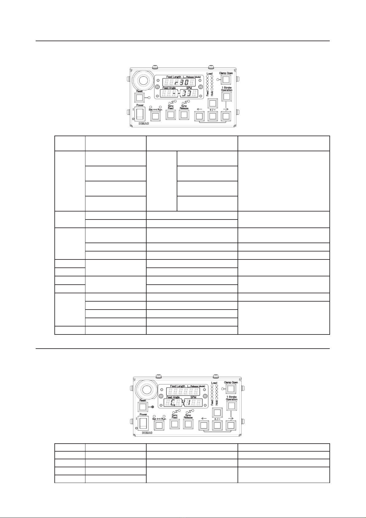
❖Caution display
This caution displays have a possibility which the feeder is reset. These displays are as the follows,
Reset : Blinking. Feed Angle SPM : C. Number
Code
C. 40 Open phase Confirmation of the power supply
C. 41 Low voltage detection Checking the voltage
C.
50 -1
C.
50 -2
Number
State / Content
Note
Motor connection anomaly
Contact failure
I - F
7.7.7.7.7.7.
666666
101010
Input stop signal during driving
press
1.0.1.0.1.0.
662662
663663
777777
1.1.1.1.1.1.
Another work shortage sensor ON
Work shortage sensor release
Another work shortage sensor release
Turn on "Sync Feed" and "Sync
Release" after turn on "Reset"
switch
664664
661661
After releasing the Emergency
stop switch, turn off the power
Turn on Reset switch after input
stop signal release
4.4.4.4.4.4.
444444
After setting a work pieces, turn
on "Reset" switch
Turning off "Sync Feed", the work
shortage sensor will disabled.
The code will display the operating state of the feeder to suit the operation state and setting
disabled state.
ENG
STOP
Contents
Method of reset
Model
number
When turning on power only, the
control panel displays the program
Feed Angle SPM
- - ] ]
-. -..].].
CC - -
C. C. -. -.
Feed Length
r30
6 CS-0173_1
This manual suits for next models
2
Other Dimac Industrial Equipment manuals

Popular Industrial Equipment manuals by other brands

Wallenstein
Wallenstein CT162 Operator's manual

ProMinent
ProMinent CHLORINSITU IIa Series Maintenance instructions

SCHUNK
SCHUNK NSE mini 90 Assembly and operating manual

Huawei
Huawei SmartLi-512V-80AHF-01 quick guide

Spirax Sarco
Spirax Sarco FT 14 Installation and maintenance instructions

Cognex
Cognex DataMan 8072 Reference manual


