Dimastech EasyXL User manual

DimasTech EasyXL
Version 1.0
ASSEMBLY MANUAL
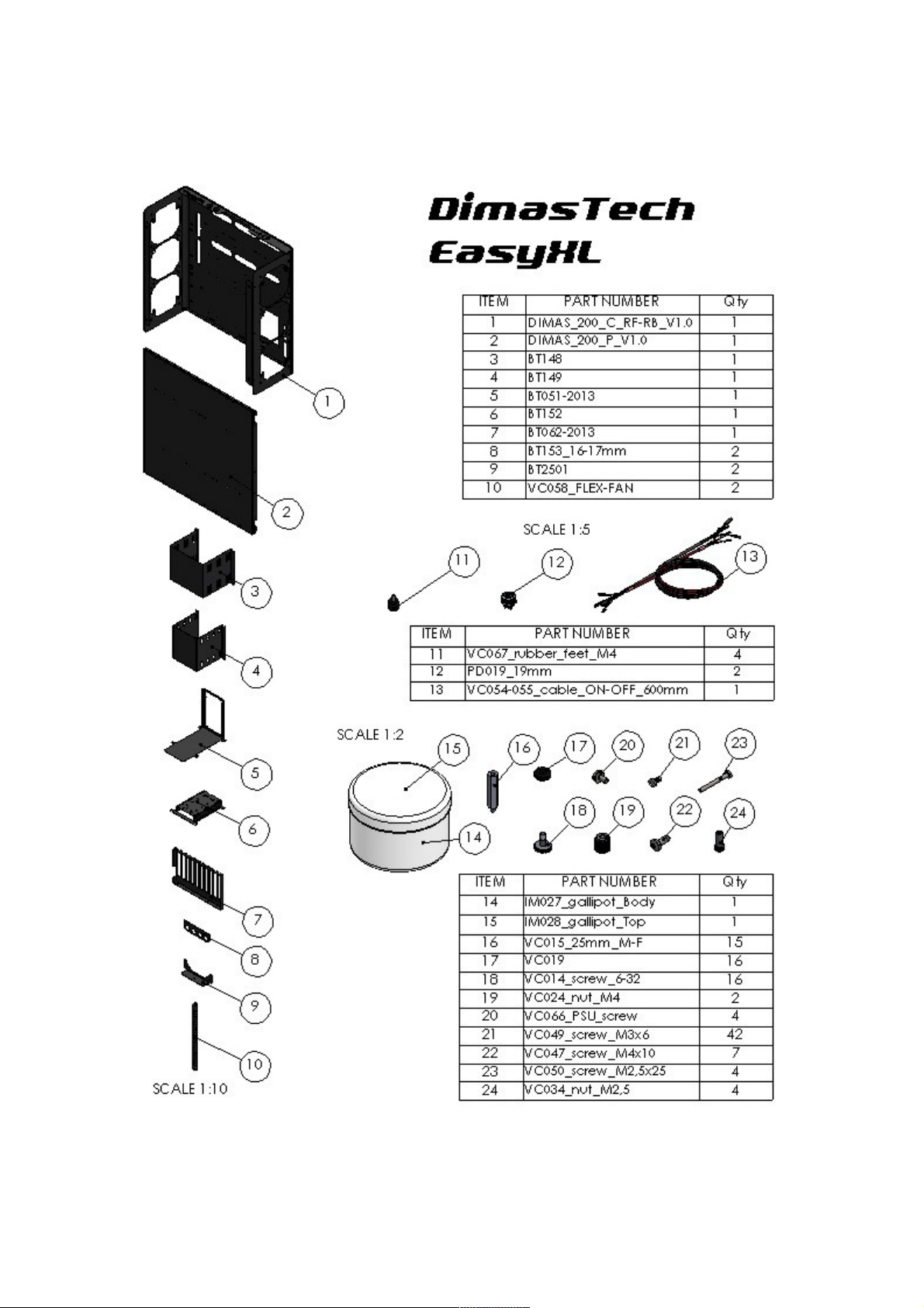
CONTENTS OF THE KIT

ASSEMBLY DimasTec EasyXL V.1.0 - FLEX-FAN
- Align VC058 (10) to BT2501
(9) and fasten wit No.1 screw
VC047_M4x10 (22), as s own
in Figure 1
- Align FAN 120 (item not
included) to BT2501 (9) on
vertical oles and fasten wit
No.2 screws VC050_M2,5x25
(23) plus No.2 knurled nuts
VC034_M2,5 (24), as s own in
figure 2
- DimasTec EasyXL V.1.0 as t e
possibility of mounting No.2 FLEX-FAN
in any of t e 6 oles wit M4 t readed
inserts at your disposal according to t e
mot erboard you ave purc ased or t e
preferred c oice, as s own in t e figure
beside. T e image as t e sole purpose
of illustrating t e possible positions of
t e parts.
Note: T e number indicated in t e brackets indicates t e corresponding
identification in t e table on t e page No.2

ASSEMBLY DimasTec EasyXL V.1.0 – STEP-1
- Assemble No.4 VC067_rubber-
feet_M4 (11) into t e dedicated
M4 t readed inserts, located at
t e base of t e
DIMAS_200_C_RF-RB_V.1.0 (1)
body, as s own in t e figure
beside
ASSEMBLY DimasTec EasyXL V.1.0 – STEP-2
- Unscrew t e No.4 screws
VC048_M3x10 oused in t e
front part of t e DimasTec
EasyXL V.1.0 and extract t e
two preassembled components
BT148 (3) and BT149 (4), as
s own in t e figure beside.
Note: T e number indicated in t e brackets indicates t e corresponding
identification in t e table on t e page No.2

ASSEMBLY DimasTec EasyXL V.1.0 – STEP-3
- Unscrew t e No.4 screws
VC048_M3x10 oused in t e
back part of t e DimasTec
EasyXL V.1.0 and extract t e
two preassembled components
BT051-2013 (5) and BT151 (6),
as s own in t e figure beside.
ASSEMBLY DimasTec EasyXL V.1.0 – STEP-4
- T e component BT148 (3) as
t e possibility to ouse inside
No.3 optical readers (items not
included), t e image as t e sole
purpose of illustrating t e possible
positions of t e parts.
- Align t e side oles of t e optical
reader wit t e slots of t e
component BT148 (3) and fasten
wit No.4 screws VC049_M3x6
(21) for eac optical reader, as
s own in t e figure beside.
Note: T e number indicated in t e brackets indicates t e corresponding
identification in t e table on t e page No.2

ASSEMBLY DimasTec EasyXL V.1.0 – STEP-5
- T e component BT149 (4) as
t e possibility to ouse inside No.4
ard-disks (items not included),
t e image as t e sole purpose of
illustrating t e possible positions
of t e parts.
- Insert No.16 VC019 (17) into t e
appropriate s aped slots
- Align t e side oles of t e ard
disk wit t e oles of VC019 (17)
and fasten wit No.4 screws
VC014_6-32 (18) for eac ard
disk, as s own in t e figure beside.
ASSEMBLY DimasTec EasyXL V.1.0 – STEP-6
- T e component BT051-2013 (5)
as t e possibility to ouse inside
No.1 power supply (item not
included), t e image as t e sole
purpose of illustrating t e
possibility positions of t e parts.
- Align t e oles in t e power
supply to t e components of t e
BT051-2013 component (5) and
fasten wit No.4 screws VC066_6-
32 (20), s own in t e figure
beside.
Note: T e number indicated in t e brackets indicates t e corresponding
identification in t e table on t e page No.2

ASSEMBLY DimasTec EasyXL V.1.0 – STEP-7
- Insert t e components BT148
(3), BT149 (4) wit t e respective
ardware installed, inside t e
DimasTec EasyXL V.1.0 and
fasten wit t e No.4 screws
VC048_M3x10 previously
extracted, as s own in t e figure
beside.
T e image as t e sole purpose of
illustrating t e possible positions
of t e parts.
ASSEMBLY DimasTec EasyXL V.1.0 – STEP-8
- Insert t e components BT051-
2013 (5), BT152 (6) wit t e
respective ardware installed,
inside t e DimasTec EasyXL
V.1.0 and fasten wit t e No.4
screws VC048_M3x10 previously
extracted, as s own in t e figure
beside.
T e image as t e sole purpose of
illustrating t e possible positions
of t e parts.
Note: T e number indicated in t e brackets indicates t e corresponding
identification in t e table on t e page No.2

ASSEMBLY DimasTec EasyXL V.1.0 – STEP-9
- Align t e slots at t e base of
t e BT062-2013 component (7)
wit t e slots at t e back of t e
DimasTec EasyXL V.1.0 and
fasten wit No.2 screws
VC047_M4x10 (22) plus No.2
knurled nuts VC024_M4 (19), as
s own in t e figure beside.
ASSEMBLY DimasTec EasyXL V.1.0 – STEP-10
- Align t e M3_ inserts of t e
component BT153 (8) wit t e
oles in t e back part of t e
DimasTec EasyXL V.1.0 and
fasten wit No.2 screws
VC049_M3x6 (21), as s own in
t e figure beside.
Note: T e number indicated in t e brackets indicates t e corresponding
identification in t e table on t e page No.2

ASSEMBLY DimasTec EasyXL V.1.0 – STEP-11
- T e DimasTec EasyXL V.1.0 as t e
possibility to mount No.9 spacers
VC015_M3_25mm_M-F (16) in any of
t e No.22 M3 t readed oles
available to you according to t e type
of mot erboard you ave purc ased
or to t e arrangement to You
preferred, t e image as t e sole
purpose of illustrating t e possible
positions of t e parts.
- Align t e spacers
VC015_M3_25mm_M-F (16) to t e
corresponding t readed oles M3 of
t e DimasTec EasyXL V.1.0 and
fasten, as s own in t e figure beside.
ASSEMBLY DimasTec EasyXL V.1.0 – STEP-12
- Align t e oles in t e mot erboard
(item not included) wit t e spacers
VC015_M3_25mm_M-F (16), and
fasten wit screws VC049_M3x6 (21),
as s own in t e figure beside.
T e number of screws to be used will
be t e same as t e spacers mounted
according to t e mot erboard, t e
image as t e sole purpose of
illustrating t e possible positions of
t e parts.
Note: T e number indicated in t e brackets indicates t e corresponding
identification in t e table on t e page No.2
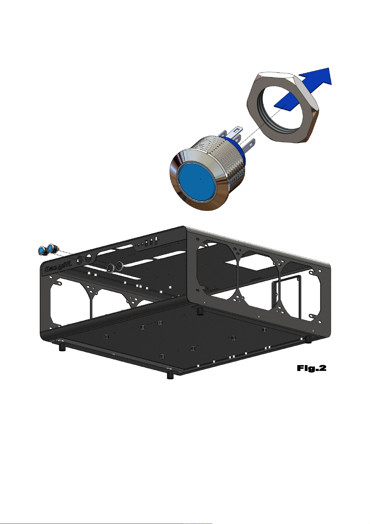
ASSEMBLY DimasTec EasyXL V.1.0 –
PD019_19mm
– Unscrew t e exagon nut of t e
pus button PD019_19mm (12), as
s own in Figure 1
- Before proceeding wit t e
assembly of t e ardware parts, it
is necessary to extract t e BT148
(3) and BT149 components (4) as
s own in STEP-2 and STEP-7.
- Align No.2 PD019_19mm (12) to t e No.2 orizontal oles in t e front of t e
body DIMAS_200_C_RF-RB_V.1.0 (1) and fasten wit t e previously unscrewed
exagon nuts, as s own in Figure 2
Note: T e number indicated in t e brackets indicates t e corresponding
identification in t e table on t e page No.2
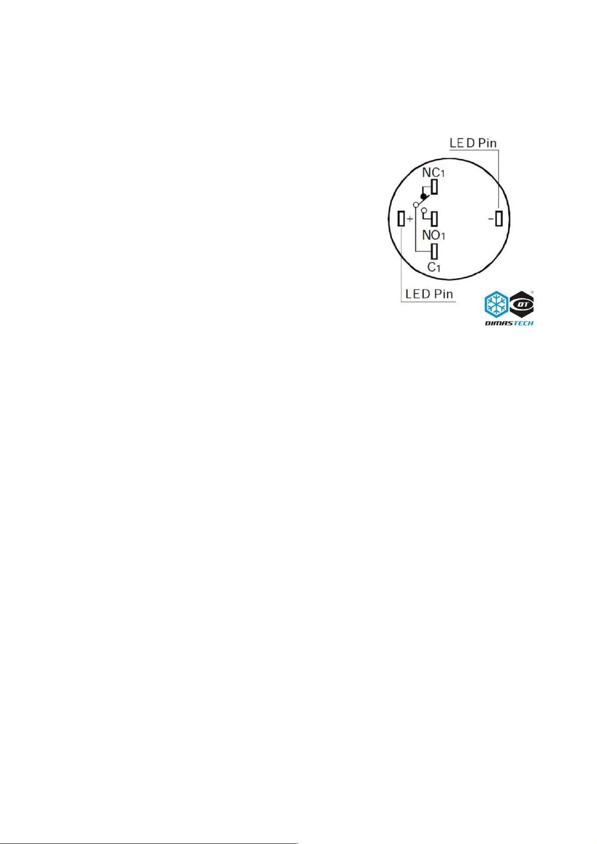
ASSEMBLY DimasTec EasyXL V.1.0 –
PD019_19mm
For power ON or reset function, connect wit out
polarity yellow cable to "NO1" and ot er Yellow
cable to "C1", t an to use t e pus button
integrated LED, connect t e black cable to "-"
and t e red cable to "+", pus button integrated
LED will work wit PWLED (power on LED) and
HDLED ( ard disk LED), please take care of
polarity, follow "-" and "+" on mot erboard
instruction.
Note: T e number indicated in t e brackets indicates t e corresponding
identification in t e table on t e page No.2
Table of contents
Other Dimastech Test Equipment manuals

Popular Test Equipment manuals by other brands


Teledyne Lecroy
Teledyne Lecroy Everywhereyoulook HDO6000B Getting started guide

Tektronix
Tektronix 7934 Operator's manual

Megger
Megger MFT1700 series quick start guide

Koehler
Koehler K41091 Operation and instruction manual

Fluke
Fluke 709 Quick reference guide

Coopers of Stortford
Coopers of Stortford F946 Instructions for use