Koehler K41091 Guide

Operation and Instruction Manual
REV A .
Koehler Instrument Company, Inc.
1595 Sycamore Avenue • Bohemia, New York 11716-1796 • USA
Toll Free: 1-800-878-9070 (US only) • Tel: +1 631 589 3800 • Fax: +1 631 589 3815
http://www.koehlerinstrument.com • e-mail: info@koehlerinstrument.com
Petroleum Testing & Analysis Instrumentation • Custom Design & Manufacturing
K41091
Micro Conradson Carbon Residue
and Ash Tester


K41091 Micro Carbon Residue and Ash Tester
Operation and Instruction Manual
K41091-Manual -1-
Table of Contents
1Introduction ...................................................................................................................2
1.1 Koehler’s Commitment to Our Customers .............................................................................................2
1.2 Recommended Resources and Publications.........................................................................................2
1.3 Instrument Specifications.......................................................................................................................3
2Safety Information and Warnings ................................................................................3
3Getting Started...............................................................................................................4
3.1 Packing List............................................................................................................................................4
3.2 Unpacking ..............................................................................................................................................4
3.3 Setup......................................................................................................................................................4
4Descriptions...................................................................................................................5
4.1 Instrument Descriptions - Front..............................................................................................................5
4.2 Instrument Descriptions - Back..............................................................................................................5
5Operation .......................................................................................................................6
5.1 Instrument Start-up.................................................................................................................................6
5.2 Starting a Test........................................................................................................................................7
5.3 Control Panel Operation.........................................................................................................................8
5.3.1 Creation of New Programs..................................................................................................................8
5.3.2 Software Configuration Functions.......................................................................................................9
5.3.3 Hardware Configuration Functions ...................................................................................................10
6Maintenance.................................................................................................................11
6.1 Maintenance Checks............................................................................................................................11
6.2 Routine Maintenance ...........................................................................................................................11
6.2.1 Cleaning of Furnace Opening and Hot Lid .......................................................................................11
6.2.2 De-Carbonizing the Furnace.............................................................................................................11
6.2.3 Temperature Check of the Furnace..................................................................................................12
6.3 Replacement Parts and Accessories List ............................................................................................13
7Diagrams......................................................................................................................14
7.1 Flow Meter Calibration Chart ...............................................................................................................14
7.2 Function Flow Chart.............................................................................................................................15
8Service..........................................................................................................................16
9Storage.........................................................................................................................16
10 Warranty.......................................................................................................................16
11 Returned Goods Policy...............................................................................................16
Notes..................................................................................................................................17

K41091 Micro Carbon Residue and Ash Tester
Operation and Instruction Manual
K41091-Manual -2-
1 Introduction
The Koehler K41091 Micro Carbon Residue and
Ash Tester is the latest design for performing
carbon residue testing in accordance to the ASTM
D4530 and D189 test methods and related test
specifications.
This manual provides important information
regarding safety, technical reference, installation
requirements, operating condition specifications,
user facility resource requirements, and operating
instructions for the micro carbon residue and ash
tester. This manual should also be used in
conjunction with applicable published laboratory
procedures. Information on these procedures is
given in section 1.2.
1.1 Koehler’s Commitment to Our
Customers
Providing quality testing instrumentation and
technical support services for research and testing
laboratories has been our specialty for more than
50 years. At Koehler, the primary focus of our
business is providing you with the full support of
your laboratory testing needs. Our products are
backed by our staff of technically knowledgeable,
trained specialists who are experienced in both
petroleum products testing and instrument service
to better understand your requirements and
provide you with the best solutions. You can
depend on Koehler for a full range of accurate and
reliable instrumentation as well as support for your
laboratory testing programs. Please do not
hesitate to contact us at any time with your
inquiries about equipment, tests, or technical
support.
Toll Free: 1-800-878-9070 (US only)
Tel: +1 631 589 3800
Fax: +1 631 589 3815
Email: info@koehlerinstrument.com
http://www.koehlerinstrument.com
1.2 Recommended Resources and
Publications
1. American Society for Testing and Materials
(ASTM)
100 Barr Harbor Drive
West Conshohocken, Pennsylvania 19428-
2959, USA
Tel: +1 610 832 9500
Fax: +1 610 832 9555
http://www.astm.org
email: service@astm.org
ASTM Publication:
ASTM D4530: Standard Test Method for
Determination of Carbon Residue (Micro
Method)
ASTM D189: Standard Test Method for
Conradson Carbon Residue of Petroleum
Products
2. International Organization for Standardization
(ISO)
1, rue de Varembé
Case postale 56
CH-1211 Geneva 20, Switzerland
Tel: 41 22 749 01 11
Fax: 41 22 733 34 30
http://www.iso.org
ISO Publication:
ISO 10370: Petroleum Products –
Determination of Carbon Residue –
Micro Method
ISO 6615: Petroleum Products –
Determination of Carbon Residue –
Conradson Method
3. Energy Institute (IP)
61 New Cavendish Street
London, WIM 8AR, United Kingdom
Tel: 44 (0)20 7467 7100
Fax: 44 (0)20 7255 1472
http://www.energyinstpubs.org.uk/
IP Publication:
IP 398: Petroleum Products –
Determination of Carbon Residue –Micro
Method
IP 13: Petroleum Products –
Determination of Carbon Residue –
Conradson Method
4. Deutsche International Norm (DIN)
http://www.din.de

K41091 Micro Carbon Residue and Ash Tester
Operation and Instruction Manual
K41091-Manual -3-
DIN Publication:
DIN 51551: Testing of Lubricants and
Liquid Fuels –Determination of Carbon
Residue –Conradson Method
1.3 Instrument Specifications
Model:
K41091
Electrical
Requirements:
230V 50/60Hz
1500W 16A
Temperature Range:
Ambient to 800°C
(1472°F)
Environment
Operating
Temperature:
15 to 30°C
Temperature
Resolution:
± 0.1°C
Furnace
Temperature Sensor
Type:
K Type Thermocouple
Furnace
Temperature Sensor
Calibration:
By Keyboard
Furnace Type:
Direct Conformance to
ASTM D4530
Cooling of the
Furnace:
Accelerate by internal
turbine at 500°C and set
point +20°C
Gas Connection on
back of instrument:
Quick connect coupling
for Rilsan Tube 4mm
Gas Connection on
pipe end:
Quick connect coupling
¼ Bsp conical to screw
Maximum Upstream
Gas Pressure:
2.5 Bar (250 kPa)
Minimum Upstream
Gas Pressure:
1 Bar (100 kPa)
Gas Type:
Air - Nitrogen
Capacity:
12 small Vials
4 small and 3 large Vials
6 large Vials
Results Storage
Capacity:
99
PC Output:
RS232 Port (2)
Test Programs:
2 Preprogrammed
18 User Programmable
Maximum Heating
Rate:
15°C/min
Over temperature
Protection Limit:
By regulated secondary
thermocouple at 900°C
Microprocessor
Safety Apparatus:
Watchdog Hardware
2 Safety Information and Warnings
Safety Considerations. The use of this
equipment may involve hazardous materials and
operations. This manual does not purport to
address all of the safety problems associated with
the use of this equipment. It is the responsibility of
any user of this equipment to investigate,
research, and establish appropriate safety and
health practices and determine the applicability of
regulatory limitations prior to use.
Equipment Modifications and Replacement
Parts. Any modification or alteration of this
equipment from that of factory specifications is not
recommended voids the manufacturer warranty,
product safety, performance specifications, and/or
certifications whether specified or implied, and
may result in personal injury and/or property loss.
Replacement parts must be O.E.M. exact
replacement equipment.
Unit Design. This equipment is specifically
designed for use in accordance with the applicable
standard test methods listed in section 1.2 of this
manual. The use of this equipment in accordance
with any other test procedures, or for any other
purpose, is not recommended and may be
extremely hazardous.
Chemical Reagents Information. Chemicals and
reagents used in performing the test may exhibit
potential hazards. Any user must be familiarized
with the possible dangers before use. We also
recommend consulting the Material Data and
Safety Sheet (MSDS) on each chemical reagent
for additional information. MSDS information can
be easily located on the internet at
http://siri.uvm.edu or http://www.sigma-
aldrich.com.

K41091 Micro Carbon Residue and Ash Tester
Operation and Instruction Manual
K41091-Manual -4-
3 Getting Started
The instructions for preparing the equipment
assume that the user is aware of the contents of
this document, which lists the warranty conditions
and important precautions.
3.1 Packing List
K41091 Micro Carbon Residue and Ash Tester
Cleaning Cable (1)
RS232 Serial Cable (2)
Software Disc (3)
Mixed Vial Holder (4)
Large Vial Holder (5)
Small Vial Holder (6)
Pipe Chimney Extension (7)
Hook for Safe Hot Lid Handling (8)
Hot Lid (9)
Insulating Lid (10)
Gas Connection Tubing (11)
Power Cord (12)
K41091-Manual Micro Carbon Residue and Ash
Tester Operation and Instruction Manual
Number designations refer to Figure 1 below:
Additional Accessories and Consumables
Available (order separately):
Part No.
Description
K41000-7
Gas Connection Kit - 2 Gas
Outputs
K41000-9
Holder for 25-50-100 g Porcelain
Crucibles
K41000-1
Pack of 6 Porcelain Crucibles, 120
ml, Tall Form
K41000-10
Pack of 6 Porcelain Crucibles, 40
ml, Tall Form
K41000-11
Pack of 6 Porcelain Crucibles, 80
ml, Low Form
K41000-2
2 mL Borosilicate Glass Sample
Vial
K41000-3
16 mL Borosilicate Glass Sample
Vial
K41100-3
16 ml vials (pack of 144) for single
use
K41100-4
2 ml vials (pack of 144) for single
use
K41000-4
2 ml Quartz sample vial, re-usable
(Ash Content Test)
K41000-5
16 ml Quartz sample vial, re-
usable (Ash Content Test)
K41000-8
4 ml Borosilicate glass sample
tube (MRC test)
3.2 Unpacking
Carefully unpack and place the instrument and
accessories in a secure location. Ensure that all
items listed on the packing list are present. Inspect
the unit and all accessories for damage. If any
damage is found, keep all packing materials and
immediately report the damage to the carrier. We
will assist you with your claim, if requested. When
submitting a claim for shipping damage, request
that the carrier inspect the shipping container and
equipment. Do not return goods to Koehler without
written authorization.
3.3 Setup
Equipment Placement. Place the instrument on a
firm, level table in an area with adequate
ventilation or in a hood. The unit may be leveled
by making minor turning adjustments to the feet
located at the base of the unit. Please note that
Koehler does not supply a level with this
equipment. The apparatus has had to be at room
temperature for several hours before to be
energized in order to avoid the risk of
condensation.
Ventilation. A fume hood or exhaust system is
required when operating the unit. Flammable
vapors and/or steam are generated during
operation and must not be permitted to
accumulate. A canopy-style hood may be used if
the height from the top of the unit to the canopy is
5 feet or less. The exhaust blower should have a
rating of 1000 C.F.M. or greater.

K41091 Micro Carbon Residue and Ash Tester
Operation and Instruction Manual
K41091-Manual -5-
Gas. The gas circuit of the apparatus can be
connected to a maximum gas pressure of 2.5 bars
(250 kPa) with the pipes and collar accessories
provided.
Power. Connect the line cords to properly fused
and grounded receptacles with the correct voltage
as indicated in section 1.3 or on the back of the
unit.
WARNING: For safety, disconnect the power
when performing any maintenance and/or
cleaning. Do NOT turn the power on unless the
bath is filled with the proper medium; otherwise,
damage may occur to the unit and the warranty
will be void.
4 Descriptions
4.1 Instrument Descriptions - Front
Figure 2: Instrument Descriptions_Front
1. Heat Light. Indicates to user that the furnace
is heating.
2. Power Button. This button controls the power
to the entire instrument.
3. Emergency Stop Button. Pushing this button
turns off the power to the entire unit.
4. Numeric Keypad. For entering sample data
and parameter values for testing.
5. Key Function Buttons. For navigation
through the instruments sub-menus.
Note: The function of these buttons and
subsequent display icons will change
depending on the menu the user is in.
6. Display. For user-friendly control of the
instrument.
7. Insulating Cover. For enhanced temperature
stability of the oven.
8. Exhaust Port. Insert Chimney Pipe Extension
to safely direct oven exhaust and vapors away
from user and into a vent.
9. Pressure Gauge. Displays pressure
measurement of inlet Gas (Air/Nitrogen).
Note: Gas Pressure can only be adjusted by
an external regulator at the source.
10. Fine Gas Flow Adjust Knob. For minimal
regulation of the gas flow into the oven.
Note: It is recommended to adjust the gas
flow with the Course Gas flow adjust knob
prior to this adjustment.
11. Flowmeter. Measures the Flow Rate of the
gas entering the oven.
12. Course Gas Flow Adjust Knob. For
regulating the gas flow entering the oven.
4.2 Instrument Descriptions - Back
Figure 3: Instrument Descriptions_Back

K41091 Micro Carbon Residue and Ash Tester
Operation and Instruction Manual
K41091-Manual -6-
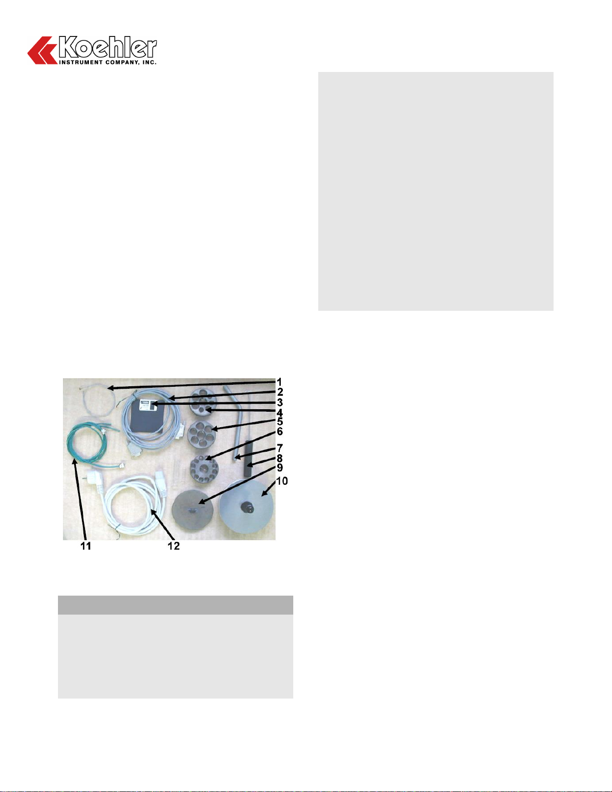
1. Gas Inlet Connections. For connection of Air
and Nitrogen Gas to the instrument from an
external source.
2. Thermocouple Port. For connection of
Furnace Thermocouple.
3. Power Outlet. For connection of line cord
plug.
4. Fuse Port. Location for Fuse replacement.
5. Watchdog Shutdown Button. Turns off
microprocessor to perform maintenance
procedures.
6. Parallel Port. 25 Pin Type Parallel Port for
connection to a Printer.
7. Serial Line 1. For connection to external PC.
8. Serial Line 2. Not used in instrument.
5 Operation
5.1 Instrument Start-up
WARNING: An apparatus showing traces of an
impact or any damage following shipping or
unpacking should not be operated.
WARNING: The apparatus must be held at room
temperature for several hours before turning on
the power in order to avoid risks caused by
condensation.
NOTE: Give detailed attention to the lid and the
top opening of the furnace for condensation. The
lid ensures that the furnace is sealed.
1. Depending on the desired use (carbon residue
or ash), the apparatus must be connected to a
source of nitrogen providing a maximum
pressure of 2.5 Bar (250 kPa) and possibly to
a source of air at a maximum pressure of 2.5
Bar (250 kPa). In order to keep a stable flow
during testing, the gas supply will have to be
regulated with a pressure reducer to stabilize
the pressure upstream.
NOTE: During the first test of using the instrument,
which should be done without sample, it is
essential to check the value of the gas flows and
to adjust them according to the pressure upstream
of the gas.
WARNING: Do not connect any additional
extension to either the chimney or the supplied
Chimney Extension Pipe in an attempt to further
evacuate the exhaust fumes. The chimney must
remain free to ensure optimal exhaust of the
system. Any connection on the chimney or its
extension pipe would be likely to cause:
- Condensates in the piping of the apparatus
- A backpressure which would disturb the test
by modifying the flows and cause leaks on the
hot lid of the furnace.
2. Connect the line cord to properly fused and
grounded receptacles with the correct voltage
as indicated in section 1.3 and to the
receptacle on the back of the unit.
WARNING: For each type of test or method used
the apparatus must be placed under a hood to
properly and safely evacuate the exhaust fumes
generated by the instrument.
3. Number designations for the following set of
directions refer to Figure 4 below:
a. If necessary, unbolt the Emergency Stop
Button (1)
b. Switch on the apparatus, by using the
circuit breaker under Lift Door beneath the
Numeric Keypad.
c. If necessary, switch on the differential (2)
then switch on the circuit breaker (3)
d. Press the Power Button to turn on the
instrument (4)
4. The apparatus will begin to boot and the
standby display screen will appear after
approximately 20 seconds.
5. The furnace will then begin heating to a
standard temperature of 50°C. The furnace
will also revert back to this temperature in
between tests. 50°C is a factory preset value
and can be adjusted by accessing the
Setpoint Function from the instruments menu
screen. See section 6.2.
WARNING: If the apparatus is powered off for a
period of more than 3 weeks, the accumulator of
the microprocessor board is discharged. The
instrument will completely reset including its
internal date and time. In the event that this does
occur, it is necessary to reset the date and time
using the maintenance function from the
instrument menu. All other parameters will be
saved in the “flashEprom” memory. In the event of
the microprocessor discharge, all operation
parameters will be saved.

K41091 Micro Carbon Residue and Ash Tester
Operation and Instruction Manual
K41091-Manual -7-
6. Basic Functions of the Apparatus:
The apparatus has been designed to perform tests
for both carbon residue and ash.
WARNING: It has been determined that at the
higher temperatures of 775°C for the Ashing test,
the temperature stability of the furnace is outside
the acceptable range of testing standards.
Two preprogrammed test procedures have been
developed and implemented into the instrument.
Program No. 1: Micro Carbon Residue
Start T (°C)
End T (°C)
Duration
(min)
Gas Flow
50
50
10
NIT
50
500
36
nit
500
500
15
nit
500
50
1
NIT
Program No. 2: Ash
Start T (°C)
End T (°C)
Duration
(min)
Gas Flow
50
50
10
NIT
50
775
60
NIT
775
775
120
AIR
775
50
1
AIR
Where:
Air = Low Flow Air
nit = Low Flow Nitrogen
AIR = High Flow Nitrogen
NIT = High Flow Nitrogen
During a test procedure, the instrument follows the
temperature profile of the program selected and
also manages the gas flow (air or nitrogen)
following the sequences defined in the program.
NOTE: The gas flow rate (High and Low Flow)
must be adjusted and set manually before starting
the test.
Flow meter Calibration Scale as per ASTM D4530
30mm = 150mL/min
120mm = 600mL/min
NOTE: It is possible to follow the temperature of
the furnace by connecting an External PC to Serial
Line 1 and using the Data Acquisition Software
provided with the accessories of the instrument.
NOTE: The calculation of residue percentage can
also be determined by the apparatus. Inputting the
initial and final weight of the samples into the
software will then calculate the residue percentage
automatically.
5.2 Starting a Test
WARNING: For either program selected, the
Instrument must be placed under a hood to
evacuate the fumes generated by the furnace
during testing. When performing an Ashing Test, it
is highly recommended to reduce the light
distillation products in the sample by using
nitrogen to avoid any risk of spontaneous
combustion. Rapid Combustion must not be
performed in the Furnace!
WARNING: It is essential to understand the
standard test method of the test to be performed.
WARNING: It will be necessary to work with a hot
furnace and samples before and after each test
run. Therefore, it is required for the operator to use
Personal Protective Equipment (PPE) and the
suitable accessories provided with the apparatus.
WARNING: When conducting an Ashing Test it is
required to use quartz vials (sold separately). The
vials provided with the instrument are of
borosilicate glass and are intended for only the
Micro Carbon Residue Test.
1. Check that the condensate tank is empty.
WARNING: The oven temperature must be below
100°C before checking the condensate tank.
Figure 5: Condensate Tank Check
2. Remove the Insulating Lid

K41091 Micro Carbon Residue and Ash Tester
Operation and Instruction Manual
K41091-Manual -8-
3. Remove the Hot Lid with the provided hook
accessory.
Figure 6: Hot Lid Handling
4. Check that the furnace exit is not clogged by
calamine. If this is the case please see the
maintenance section of this manual.
5. Place the sample vial holder with desired
samples in the furnace with the hook
accessory provided.
NOTE: Be cautious of the walls of the furnace as
the surface is maintained at an above ambient
temperature prior to testing.
Figure 7: Sample Vial Holder Handling
6. Replace the Hot Lid with the hook accessory
to ensure a tight seal.
7. Replace the Insulating Lid on the Furnace.
8. Make sure the Gas Feeder Valves from the
Gas Source are Open.
9. Check that the ventilation hood is running and
that the chimney extension pipe is properly
installed on the Furnace Chimney.
10. Begin the test by pressing the “Go” key on the
display panel.
11. Enter the ID number for each sample.
12. If desired, enter the weights of the samples.
This allows for an automatic calculation of the
percentage (ratio) of residue remaining at the
end of the test.
13. Choose the desired program (Micro Carbon
Residue or Ash).
14. Confirm the launching of the test by pressing
“Go” once again on the display panel.
15. The instrument will then sound a series of
beeps. The display will now indicate the
temperature of the furnace, the duration of the
test, the current segment of the test program
running, and the limiting values of the
temperature of the current segment.
Figure 8: Display Parameters during Test
16. At the end of the test, the instrument will
indicate the status to the operator on the
display. Wait for this message before
removing the samples from the furnace.
NOTE: Although the instrument authorizes the
user to remove the samples, it is necessary to be
extremely careful because of the high temperature
of the furnace and samples.
5.3 Control Panel Operation
5.3.1 Creation of New Programs
In addition to the Two (2) factory preinstalled
programs, the user may create custom programs.
Each program is comprised of 4 segments just as
the preprogrammed procedures are structured.
Each temperature segment is defined by its initial
temperature and its final temperature.
The user must then also define the time duration
of each segment as well as the type of gas and its
flow rate.

K41091 Micro Carbon Residue and Ash Tester
Operation and Instruction Manual
K41091-Manual -9-
The maximum time duration is 240 minutes per
segment. The type of gas flow to choose from is
listed in section 5.1 of this manual.
NOTE: The Temperature Rate must not exceed
15°C per minute in order to maintain the condition
of the Furnace.
Creation or Modification:
1. From the main menu press the “Go” key
located at the bottom left corner of the screen.
2. Next press the “Program” key at the bottom
right corner of the screen.
3. Enter the number of the program to modify or
create. This will bring you to the screen
illustrated in Figure 9 below.
Figure 9: Program Parameter Screen
4. Pressing the “Validate the Parameter” key
displays the type of gas and flow available.
5. Alphanumeric Keyboard Function. Pressing
the “A…Z” key displays a table with column
headings and lines allowing the user to select
a letter, figure or symbol for inputting a sample
ID or naming a newly created program. Please
see Figure 10 below:
6. Weight Input Function. This function makes
it possible to enter the weights of the samples
so that the apparatus can make a calculation
after the weights entered at the end of the
test. When entering a weight value, the
numbers will start on the operators left and
scroll to the right as additional numbers are
entered. To enter the desired value it may be
required to enter a number of “Zeros” after the
value has been entered. The standard number
of significant figures is shown below:
XX.XXXXX G
For example, to enter 2.45 G, the user must
enter 2, then 4, then 5 followed by three
Zeros. This places the two (2) in the single
digit place resulting in the desired value.
7. Set Point Function. This function allows the
user to input the idle set point temperature of
the furnace between tests. This value is
limited to the range from 20 to 80°C
8. Standby Function. This function allows the
user to shut down the apparatus via the
control panel without having to switch off the
circuit breaker or push the emergency stop
button. This method of shut down avoids
restarting the circuit breaker at the time of the
next power up. Upon activation of this
function, the instrument automatically shuts
down after a few seconds.
5.3.2 Software Configuration Functions
The following functions are accessible via the
Software Function.
From the main menu press the “Configuration
Key”located at the bottom right corner. During
this functions’first use a password is not required
to enter this menu. A password must be created in
the “New Password” function screen to implement
this security feature. Once in the Software
Function Menu, press next and enter the “New
Password Function” screen. See step 5 below for
further detail on this function.
1. Buzzer Function. This function allows the
user to choose between a continuous buzzer
that sounds at the end of the test until the
operator turns it off or a buzzer that sounds for
3 minutes.
2. Stop Ventilation Function. This function is
automatically set to 20°C above the Idle Set
Point Temperature value. The minimum value
for this set point is 80°C. The fan starts at
500°C and stops at the Idle set point plus
20°C.
3. Stop Safety Function. This function allows
the user to set a safety temperature limit. This
temperature is measured on the Furnace
temperature probe. If a malfunction occurs
and the temperature of the furnace exceeds
this value, the microprocessor cuts the heating

K41091 Micro Carbon Residue and Ash Tester
Operation and Instruction Manual
K41091-Manual -10-
of the furnace. This value can be adjusted
from 600 to 900°C.
4. Remote Loading Function. This function
allows for reloading of the software or for
installing a new version of the software via the
Serial port located on the back of the
instrument.
5. New Password Function. This function
allows for the user to create and change the
password allowing access to the Maintenance
and Configuration Functions of the instrument.
Enter the desired password and follow the
steps indicated on the display.
6. Name Apparatus Function. When the
instrument is delivered, the “name of the
apparatus” is its serial number. This number
appears, amongst other printouts, on the
logbook of the instruments configuration. This
function allows for users who wish to rename
the apparatus, change its name via the
alphanumeric function screen.
7. Graphic Impression Function. The function
allows the user to choose between a simplified
version of the results or a graphical result
printout.
8. Printer Function. This function allows the
user to select the print out format to be either
40 or 80 characters in width.
5.3.3 Hardware Configuration Functions
The following functions are accessible via the
Hardware Function. From the main menu press
the “Configuration Key” located a the bottom right
corner. After entering the user password, the
following menu will feature the aforementioned
“Software Function” key as well as the
“Hardware Function”, “Date/Time” and “Help”
keys. Press the “Hardware Function” key which
is the second button from the right.
1. Language Function. This function allows the
user to convert the screens and the
impressions within the instrument from
between English and French.
2. Unit Function. This function allows the user to
choose the unit of measure for the
temperature of the furnace. Either in degrees
Celsius or Fahrenheit.
3. Calibration Function. This function allows
the user to calibrate the furnace temperature
probe.
3.1 Physical Calibration. This calibration is
done by entering three (3) temperature
points via the keyboard. Enter these
points by first replacing the furnace
thermocouple with a temperature
simulator. To do this, open remove the
furnace thermocouple from the port
located on the back of the instrument
(Section 4.2, Point 2) and replace with the
temperature simulator. The instrument will
now be able to communicate with the
simulator. It is recommended to use 50°C,
250°C, and 500°C as your points of
calibration. After the calibration, it is highly
recommended to print the configuration
logbook of the instrument. By doing so,
you will have a copy of the calibration
performed and will be able to refer to the
values entered.
3.2 Point Calibration. This calibration allows
the user to input the calibration values
previously determined and found on a
Configuration Logbook without having to
repeat a physical calibration with the
temperature simulator.
3.3 View Calibration Function. This function
allows the user to see the calibration
values on the display.
4. Offset Temperature Function. This function
allows the user to input the temperature offset
for the cold welding compensation sensor of
the furnace thermocouple. The user must
simply enter a correct room temperature value
which will act as an offset temperature.
5. Test Function. This function is mainly used
for instrument maintenance. This function
allows the user to control each physical
function of the instrument to ensure proper
operation. This includes instrument heating,
electro-valve, turbine, and buzzer function.
5.1 Self Diagnosis. The function allows the
user to automatically run a complete cycle
of operation for each element of the
apparatus and print out a report to make
an instrument diagnosis.
5.2 Logbook Function. This function allows
the user to print the Configuration
Logbook which features all the current

K41091 Micro Carbon Residue and Ash Tester
Operation and Instruction Manual
K41091-Manual -11-
parameters and configuration of the
instrument. It is highly recommended to
print this logbook before and after each
and every change made by the user to the
instrument. This makes it possible to track
calibrations, parameter and other
configuration values which may have been
modified inadvertently.
6. Date/Time Function. This function allows the
user to setup the date and time of the
instrument.
WARNING: If the instrument is left off for a period
of three weeks, the date and time will reset. In this
event, it is required to use this function to re-enter
date and time values for reporting purposes.
6 Maintenance
WARNING. Disconnect power to the unit before
servicing to avoid exposure to high voltages
and/or temperatures which may result in personal
injury or death. If you have any questions about
maintaining your equipment, then please do not
hesitate to contact the Koehler technical service
department.
The K41091 requires little routine maintenance to
provide many years of continuous service.
However, over the course of time, some
instrument parts may need to be replaced. When
ordering replacement part(s), please provide the
model number, serial number, and product
shipment date of your equipment so that we can
ensure you will receive the proper replacement
part(s).
6.1 Maintenance Checks
1. Before each test it is recommended to check
the Furnace and Condensate Tank for
Clogging and Overflow. The handling of these
condensates or residues requires much
precaution. These residues are very toxic and
require the user to wear Personal Protective
Equipment (PPE) when handling.
2. Before each test it is recommended to check
the furnace exhaust. The exhaust must be
free from calamine. If the apparatus has
calamine deposits in the furnace exhaust, it is
recommended to remove the deposits using
the cleaning cable provided.
6.2 Routine Maintenance
Depending on the frequency of use and the type of
samples being tested, it is recommended to
perform routine maintenance procedures. For
example, an Ash Test would reduce the amount of
deposits formed in the furnace but would generate
many condensates. With Ash Testing, it is then
necessary to frequently monitor the condensate
tank as well as the furnace exhaust.
6.2.1 Cleaning of Furnace Opening and Hot Lid
The top opening of the Furnace seals by means of
the metal-metal contact between the furnace and
the hot lid. Therefore, it is critical to check that the
lid is free from any shock or impact damage. Also,
ensure both the hot lid and the furnace opening
rim is free from any calamine deposits.
Use steel wool to clean the hot lid and furnace
opening of all deposits. Take careful attention not
to damage the metal. Do not use an abrasive
cloth or other material when cleaning.
NOTE: Each furnace and hot lid are manufactured
and factory test together to ensure proper sealing
of the furnace. They are both assigned an identical
given number. See Figure 10 below: Before
testing, make sure the lid and furnace have
matching numbers.
Figure 10: Hot Plate ID Number
6.2.2 De-Carbonizing the Furnace
The exit at the bottom of the furnace is a major
point of calamine deposition and accumulation. It
is recommended to cleaning this area regularly
using the cleaning cable provided. See Cleaning
Steps below:
When the Furnace is off and at room
temperature, remove the condensate tank.
Remove the insulating lid, then the hot lid.
Insert the cleaning cable through the top of
the furnace and into the bottom exit. See
Figure 11 below:

K41091 Micro Carbon Residue and Ash Tester
Operation and Instruction Manual
K41091-Manual -12-
Figure 11: Cleaning Cable_Top View
Grab the end of the cleaning cable from
where the condensate tank normally sits.
See Figure 12 below:
Figure 12: Cleaning Cable_Bottom View
With a back and forth movement and
directing the cable in all direction
simultaneously, clean the pipe of all
calamine deposits.
Check the state of the chimney and chimney
extension pipe for calamine deposits and
clean in the same manner.
6.2.3 Temperature Check of the Furnace
To check the temperature of the furnace it is
necessary for a control thermocouple to be in
place. In order to make this possible, the hot lid
has a small thermocouple port located along the
outside. If the actual temperature of the furnace
does not correlate to the reading on the
instrument, check the calibration of the furnace
thermocouple. See the location of the
thermocouple port in Figure 13 below:
Figure 13: Hot Lid Thermocouple Port

K41091 Micro Carbon Residue and Ash Tester
Operation and Instruction Manual
K41091-Manual -13-
6.3 Replacement Parts and Accessories List
Please Inquire with Koehler Customer Service for item part numbers.
Description
Cleaning Cable
Mixed Vial Holder
Small Vial Holder
Large Vial Holder
Chimney Extension Pipe
Gripping Hook
Complete Furnace
Furnace Thermocouple
Safety Thermocouple
Thermal Printer
Paper for Thermal Printer
Insulating Lid
Small Vial, Borosilicate
Large Vial, Borosilicate
Long Vial, Borosilicate
Borosilicate Vial, 12mm dia, 72mm height
Support for Porcelain Crucible
Control Thermocouple w/ cable
Furnace Thermocouple Calibration Cord
Upstream Pressure Gauge
Condensate Tank
Joint for Condensate Tank
Flowmeter
Connection Tubing for Gas Source, 1m
Gas Connection Kit
Cooling Harness

K41091 Micro Carbon Residue and Ash Tester
Operation and Instruction Manual
K41091-Manual -14-
7 Diagrams
7.1 Flow Meter Calibration Chart

K41091 Micro Carbon Residue and Ash Tester
Operation and Instruction Manual
K41091-Manual -15-
7.2 Function Flow Chart

K41091 Micro Carbon Residue and Ash Tester
Operation and Instruction Manual
K41091-Manual -16-
8 Service
Under normal operating conditions and with
routine maintenance, the K41091 Micro Carbon
Residue and Ash Tester should not require
service. Any service problem can be quickly
resolved by contacting Koehler’s technical service
department either by letter, phone, fax, or email. In
order to assure the fastest possible service,
please provide us with the following information.
Model Number:
Serial Number:
Date of Shipment:
9 Storage
This laboratory test instrument is equipped with
electrical components. Storage facilities should be
consistent with an indoor laboratory environment.
This testing equipment should not be subjected to
extremes of temperature and/or moisture.
This equipment was shipped from the factory in
a corrugated cardboard container. If long term
storage is anticipated, re-packing the instrument in
a water-resistant container is recommended to
ensure equipment safety and longevity.
10 Warranty
We, at Koehler, would like to thank you for your
equipment purchase, which is protected by the
following warranty. If within one (1) year from the
date of receipt, but no longer than fifteen (15)
months from the date of shipment, Koehler
equipment fails to perform properly because of
defects in materials or workmanship, Koehler
Instrument Company, Inc. will repair or, at its sole
discretion, replace the equipment without charge
F.O.B. its plant, provided the equipment has been
properly installed, operated, and maintained.
Koehler Instrument Company must be advised in
writing of the malfunction and authorize the return
of the product to the factory. The sole
responsibility of Koehler Instrument Company and
the purchaser’s exclusive remedy for any claim
arising out of the purchase of any product is the
repair or replacement of the product. In no event
shall the cost of the purchaser’s remedy exceed
the purchase price, nor shall Koehler Instrument
Company be liable for any special, indirect,
incidental, consequential, or exemplary damages.
KOEHLER INSTRUMENT COMPANY, INC.
DISCLAIMS ALL OTHER WARRANTIES,
EXPRESSED OR IMPLIED, INCLUDING ANY
IMPLIED WARRANTIES OF FITNESS FOR A
PARTICULAR PURPOSE. Please save the
shipping carton in the event the equipment needs
to be returned to the factory for warranty repair. If
the carton is discarded, it will be the purchaser’s
responsibility to provide an appropriate shipping
carton.
11 Returned Goods Policy
To return products for credit or replacement,
please contact Koehler Customer Service with
your purchase order number, our packing
list/invoice number, the item(s) to be returned and
the reason for the return. You will be issued a
Returned Authorization (RA) number, which must
be prominently displayed on the shipping
container when you return the material to our
plant. Shipping containers without an RA number
prominently displayed with will be returned to the
sender. Goods must be returned freight prepaid.
Returns will be subject to a restocking charge, the
application of which will depend upon the
circumstances necessitating the return. Some
returns cannot be authorized, including certain
products purchased from outside vendors for the
convenience of the customer, products
manufactured on special order, products shipped
from the factory past ninety (90) days, and
products which have been used or modified in
such a way that they cannot be returned to stock
for future sale.

K41091 Micro Carbon Residue and Ash Tester
Operation and Instruction Manual
K41091-Manual -17-
Notes

K41091 Micro Carbon Residue and Ash Tester
Operation and Instruction Manual
K41091-Manual -18-
Notes
Table of contents
Other Koehler Test Equipment manuals