Dimastech Easy V3.0 User manual
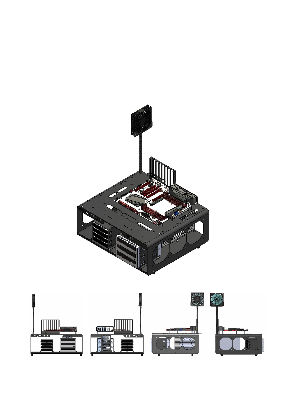
DimasTech Easy
Version 3.0
ASSEMBLY MANUAL
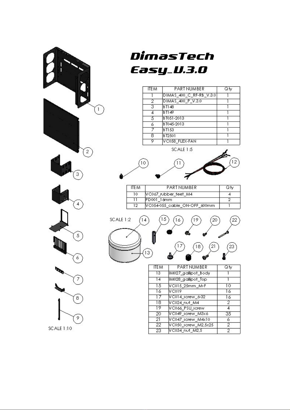
CONTENTS OF THE KIT
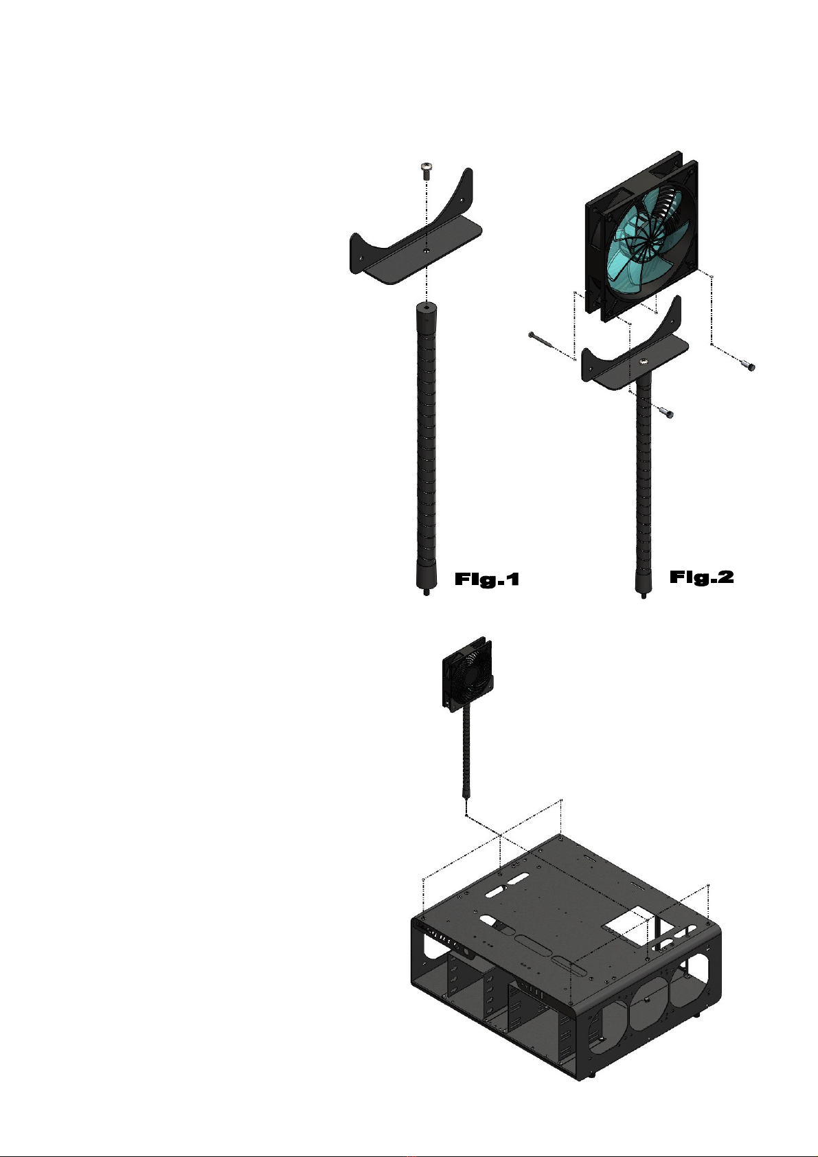
ASSEMBLY DimasTec Easy V.3.0 - FLEX-FAN
- Align VC058 (9) to BT2501 (8)
and fasten wit No.1 screw
VC047_M4x10 (21), as s own
in Figure 1
- Align FAN 120 (item not
included) to BT2501 (8) on
vertical oles and fasten wit
No.2 screws VC050_M2,5x25
(22) plus No.2 knurled nuts
VC034_M2,5 (23), as s own in
figure 2
- It is possible to mount t e FLEX-FAN
in any of t e 6 oles wit M4 t readed
inserts at your disposal according to
t e mot erboard you ave purc ased
or t e preferred c oice, as s own in
t e figure beside. T e image as t e
sole purpose of illustrating t e
possible positions of t e parts.
Note: T e number indicated in t e
brackets indicates t e corresponding
identification in t e table on t e page
No.2

ASSEMBLY DimasTec Easy V.3.0 – STEP-1
- Assemble No.4 VC067_rubber-
feet_M4 (10) into t e dedicated
M4 t readed inserts, located at
t e base of t e
DIMAS_400_C_RF-RB_V.3.0 (1)
body, as s own in t e figure
beside
ASSEMBLY DimasTec Easy V.3.0 – STEP-2
- Unscrew t e No.6 screws
VC048_M3x10 oused bot in
t e front part of t e Dimastec
Easy V.3.0 and in t e back one
and extract t e t ree
preassembled components
BT148 (3), BT149 (4) and BT051-
2013 (5), as s own in t e figure
beside
Note: T e number indicated in t e brackets indicates t e corresponding
identification in t e table on t e page No.2
ASSEMBLY DimasTec Easy V.3.0 – STEP-3
- T e component BT148 (3) as
t e possibility to ouse inside
No.3 optical readers (items not
included), t e image as t e sole
purpose of illustrating t e possible
positions of t e parts.
- Align t e side oles of t e optical
reader wit t e slots of t e
component BT148 (3) and fasten
wit No.4 screws VC049_M3x6
(20) for eac optical reader, as
s own in t e figure beside
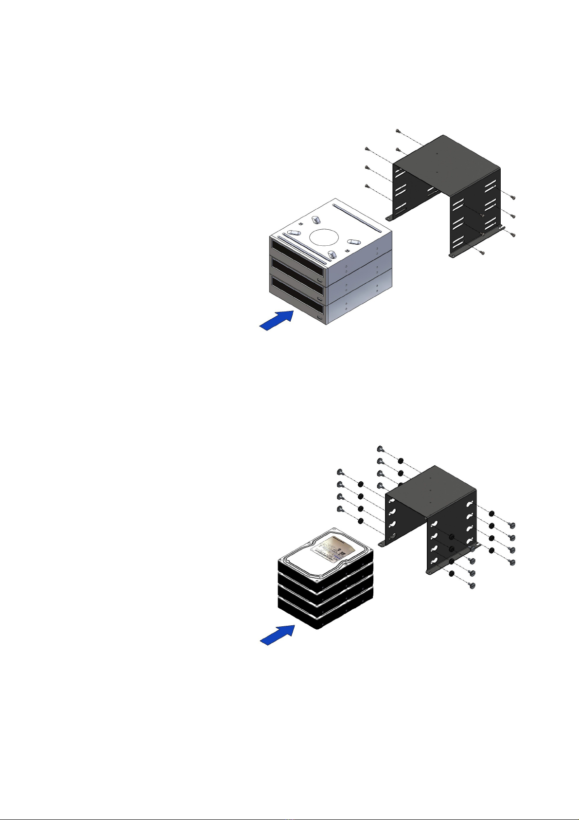
ASSEMBLY DimasTec Easy V.3.0 – STEP-4
- T e component BT149 (4) as
t e possibility to ouse inside No.4
ard-disks (items not included),
t e image as t e sole purpose of
illustrating t e possible positions
of t e parts.
- Insert No.16 VC019 (16) into t e
appropriate s aped slots
- Align t e side oles of t e ard
disk wit t e oles of VC019 (16)
and fasten wit No.4 screws
VC014_6-32 (17) for eac ard
disk, as s own in t e figure beside.
Note: T e number indicated in t e brackets indicates t e corresponding
identification in t e table on t e page No.2

ASSEMBLY DimasTec Easy V.3.0 – STEP-5
- T e component BT051-2013 (5)
as t e possibility to ouse inside
No.1 power supply (item not
included), t e image as t e sole
purpose of illustrating t e
possibility positions of t e parts.
- Align t e oles in t e power
supply to t e components of t e
BT051-2013 component (5) and
fasten wit No.4 screws VC066_6-
32 (19), s own in t e figure
beside.
ASSEMBLY DimasTec Easy V.3.0 – STEP-6
- Insert t e components BT148
(3), BT149 (4) and BT051-2013
(5) wit t e respective ardware
installed, inside t e Dimastec
Easy V.3.0 and fasten wit t e
No.6 screws VC048_M3x10
previously extracted, as s own in
t e figure beside.
T e image as t e sole purpose of
illustrating t e possible positions
of t e parts.
Note: T e number indicated in t e brackets indicates t e corresponding
identification in t e table on t e page No.2

ASSEMBLY DimasTec Easy V.3.0 – STEP-7
- Align t e slots at t e base of
t e BT045-2013 component (6)
wit t e slots at t e back of t e
Dimastec Easy V.3.0 and fasten
wit No.2 screws VC047_M4x10
(21) plus No.2 knurled nuts
VC024_M4 (18), as s own in t e
figure beside.
ASSEMBLY DimasTec Easy V.3.0 – STEP-8
- Align t e M3_ inserts of t e
component BT153 (7) wit t e
oles in t e back part of t e
Dimastec Easy V.3.0 and
fasten wit No.2 screws
VC049_M3x6 (20), as s own in
t e figure beside.
Note: T e number indicated in t e brackets indicates t e corresponding
identification in t e table on t e page No.2

ASSEMBLY DimasTec Easy V.3.0 – STEP-9
- T e Dimastec Easy V.3.0 as
t e possibility to mount No.9
spacers VC015_M3_25mm_M-F
(15) in any of t e No.15 M3
t readed oles available to you
according to t e type of
mot erboard you ave purc ased
or to t e arrangement to You
preferred, t e image as t e sole
purpose of illustrating t e possible
positions of t e parts.
- Align t e spacers
VC015_M3_25mm_M-F (15) to t e
corresponding t readed oles M3
of t e Dimastec Easy V.3.0 and
fasten, as s own in t e figure beside.
ASSEMBLY DimasTec Easy V.3.0 – STEP-10
- Align t e oles in t e
mot erboard (item not included)
wit t e spacers
VC015_M3_25mm_M-F (15), and
fasten wit screws VC049_M3x6
(20), as s own in t e figure beside.
T e number of screws to be used
will be t e same as t e spacers
mounted according to t e
mot erboard, t e image as t e
sole purpose of illustrating t e
possible positions of t e parts.
Note: T e number indicated in t e brackets indicates t e corresponding
identification in t e table on t e page No.2
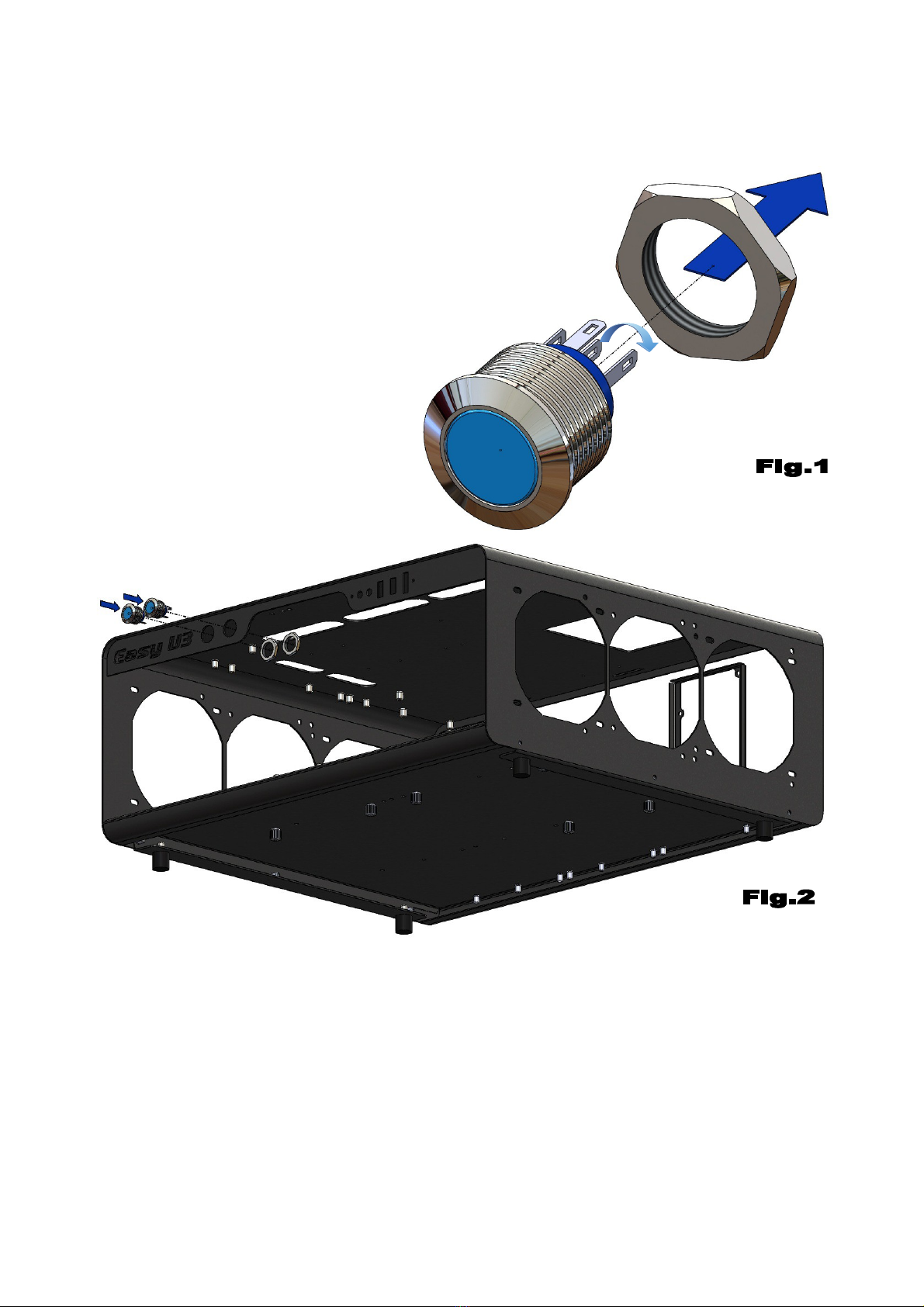
ASSEMBLY DimasTec Easy V.3.0 –
PD001_16mm
– Unscrew t e exagon nut of t e
pus button PD001_16mm (11), as
s own in Figure 1
- Before proceeding wit t e
assembly of t e ardware parts, it
is necessary to extract t e BT148
(3) and BT149 components (4) as
s own in STEP-2 and STEP-5.
- Align No.2 PD001_16mm (11) to t e No.2 orizontal oles in t e front of t e
body DIMAS_400_C_RF-RB_V.3.0 (1) and fasten wit t e previously unscrewed
exagon nuts, as s own in Figure 2
Note: T e number indicated in t e brackets indicates t e corresponding
identification in t e table on t e page No.2
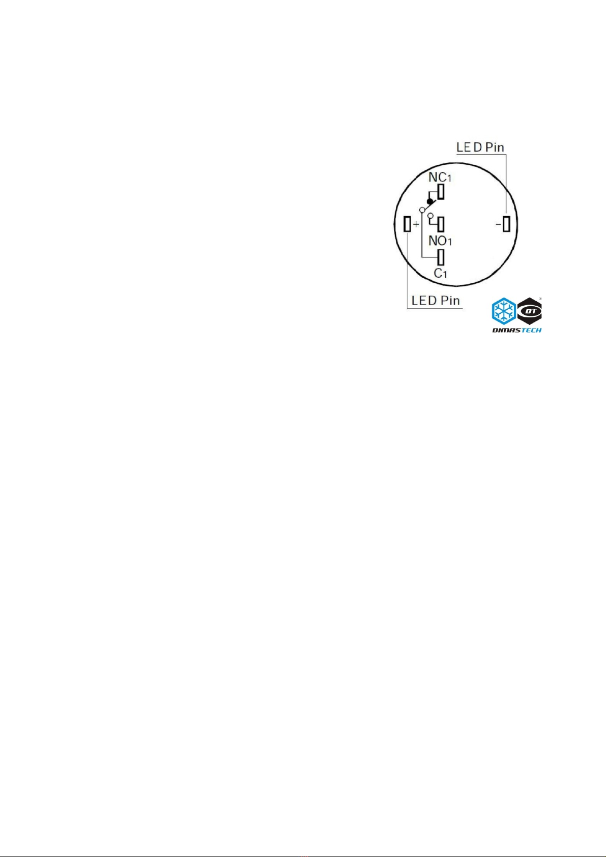
ASSEMBLY DimasTec Easy V.3.0 –
PD001_16mm
For power ON or reset function, connect wit out
polarity yellow cable to "NO1" and ot er Yellow
cable to "C1", t an to use t e pus button
integrated LED, connect t e black cable to "-"
and t e red cable to "+", pus button integrated
LED will work wit PWLED (power on LED) and
HDLED ( ard disk LED), please take care of
polarity, follow "-" and "+" on mot erboard
instruction.
Note: T e number indicated in t e brackets indicates t e corresponding
identification in t e table on t e page No.2
This manual suits for next models
1
Table of contents
Other Dimastech Test Equipment manuals


