Dino AGP-1 User manual

AGP-1 Analog Guitar Effects Processor
World’s First Programmable Analog Multi-Effects
Owner’s Manual
(Version 3.1)
Copyright © 2009-2012 Tech-in-Mind Electronics
All rights reserved. No part of this publication may be reproduced in
any form without the permission of Tech-in-Mind Electronics.
_______________________________________________________________________________________
3
Introduction
Thank you and congratulations on your choice of AGP-1 Analog Guitar Effects Processor. It is a
very innovative product and also a world’s first programmable analog multi-effects. By combining
both advantages of digital multi-effects (compact and convenience of use) and analog effect pedal
(natural and extremely good sound quality), this processor is launched with many amazing features
such as superior sound quality, small size, light weight, compact and very user friendly. This
processor contains three major parts:
Sound Management System (SMS)
(1) Accepts sound parameters and system settings from four user Rotate-Press knobs (located
below the LCD).
(2) Save/Load sound parameters and system settings.
(3) Command onboard and external plug-in analog sound modules.
(4) Organize different analog sound modules to form wide variety of guitar sound effects.
(5) Accepts commands of sound Bank/Patch switching, Patch/Pedal mode switching and Tuner
ON/OFF switching from five metal foot switches.
Analog Sound Modules
(1) They are guitar signal processing devices operating with pure analog circuitry. They can be
looked like as tiny, highly integrated and compact guitar effect pedals.
(2) Their sound parameters and ON/OFF state are commanded by SMS.
(3) Ten sound module slots are available on main board. All plug-in analog sound modules can be
easily changed their plug-in location by user to form many thousands of combination and sound
effects.
Mixer
(1) Accepts external audio sources and mixes them together with your favor guitar effect sound to
form a volume-controllable audio signal output.
(2) Audio input can be either CD music, MP3, computer backing music like Guitar-Pro or any other
sound source from electronic musical instruments.
(3) This processor provides three kinds of stereo audio output interface (RCA, XLR, 1/4” phone
jack) and one true-bypass mono output jack for guitar power amplifier.
(4) Four control knobs are used to facilitate the controls of metronome volume, guitar effect output
balance, external audio inputs volume and master audio output volume.
Product Features
(1) Total 20 groups of user settings storage, 4 Banks x 5 Patches.
(2) Each patch has its own Pedal-Mode. High flexibility in taking control of each analog sound
module's ON/OFF state.
_______________________________________________________________________________________
4
(3) 2.5” mono LCD display with blue backlight.
(4) Five heavy duty metal foot switches with LED indicator.
(5) Built-in guitar tuner.
(6) Built-in metronome with dual-color LED beat blinking.
(7) Built-in stereo headphone amplifier.
(8) Ten sound module plug-in slots and one external effect Send/Return Loop.
(9) Three onboard analog sound modules: 7-Bands Global Equalizer, Speaker Simulator, Stereo
Mixer.
(10) Many plug-in analog sound modules available for your choice: Compressor/NoiseGate,
Overdrive, Metal-Distortion, Hot-Distortion, Fuzz, Chorus, Flanger, Delay/Echo/Reverb,
Acoustic Simulator, Auto-Wah, Phaser, Octaver and Tremolo, and many more coming in future.
(11) All analog sound modules are turned ON/OFF by electro-mechanical true bypass switches.
(12) A very cost effective way to create many more analog guitar sound effects by plugging more
analog sound modules into sound module slots.
(13) Two external stereo audio input interfaces: RCA, 1/4” phone jack.
(14) Three stereo output interfaces: RCA, XLR, 1/4” phone jack.
(15) One true bypass mono output jack for guitar amplifier.
(16) Four Rotate-Press parameters control knobs.
(17) Four mixer control knobs.
(18) System firmware is upgradeable (using RS-232 on rear panel) by downloading latest firmware
from official website.
(19) Auto DC power polarity detection (center positive or center negative is not a concern).
(20) Wide range of DC voltage input: DC 9V to 12V, 1000mA or above.
(21) Dimensions: 33cm x 18cm x 5cm
(22) Weight: 2.5kg
What They Are and What They Do
(Please refer to “Panel View Diagram”)
(1) LCD
Displays useful information like showing which Bank/Patch is in use, patch name, which analog
sound module is in use, and many others.
(2) Beat LED
Dual colors LED indicator for metronome, redĺ1
st
beat, blueĺ2
nd
to 4
th
beat.
(3) Mixer Control Knobs
Metronome Volume: Adjust the metronome volume.
NOTE: No metronome output to “True Bypass Output” if Mixer is OFF.
Tone Pan: Control guitar sound balance.
Rotate anticlockwise to shift guitar sound to left channel or rotate clockwise to shift guitar sound to

_______________________________________________________________________________________
5
right channel.
NOTE: This will only work for stereo output XLR, RCA and stereo phone jack, not applicable to
TRUE BYPASS OUTPUT jack.
AUX/CD Volume: Control AUX/CD input volume to mixer.
NOTE: TRUE BYPASS OUTPUT will only output this signal when Mixer is ON.
Master Volume: Control the mixed audio signals overall volume output. Setting to middle will have
1:1 gain ratio.
NOTE: Not applicable to “True Bypass Output” if Mixer is OFF.
(4) Patch LEDs
Indicates which patch is in use.
(5) Metal Foot Switches
Five switches are used for selecting different sound patch. Step 1 & 2 simultaneously to enter guitar
tuner mode, step 2 & 3 simultaneously to enter pedal mode, or step 3 & 4 for bank down or step 4 &
5 for bank up.
(6) Parameter Control Knobs
These 4 knobs can be rotated clockwise/anticlockwise or pressed for adjusting/selecting different
system variables and parameters.
(7) RS-232
Connect to PC COM port for firmware update.
(8) DC In
Auto polarity detection DC power input.
(9) Guitar Input
Connect to guitar output jack.
(10) True Bypass Output
Connect to guitar amplifier. It will be a true bypass output when mixer is disabled.
(11) Phones
Plug stereo headphone to this jack.
(12) AUX In
Connect to any external stereo audio signal source like MP3, electric musical instrument or
computer backing music.
_______________________________________________________________________________________
6
(13) Ext Loop Send/Return
Connect “Send” to external effect pedal’s input and “Return” to pedal’s output.
(14) CD In
Same as “AUX IN”, it will be disabled when there is a connector plugged into “AUX IN”.
(15) Mixer Out (RCA/XLR)
It is a mixed stereo signal output (guitar signal & external audio signal). RCA provides a convenient
way for sound connection. If superior sound quality is required for recording, two XLR connectors
are highly recommended to connect.
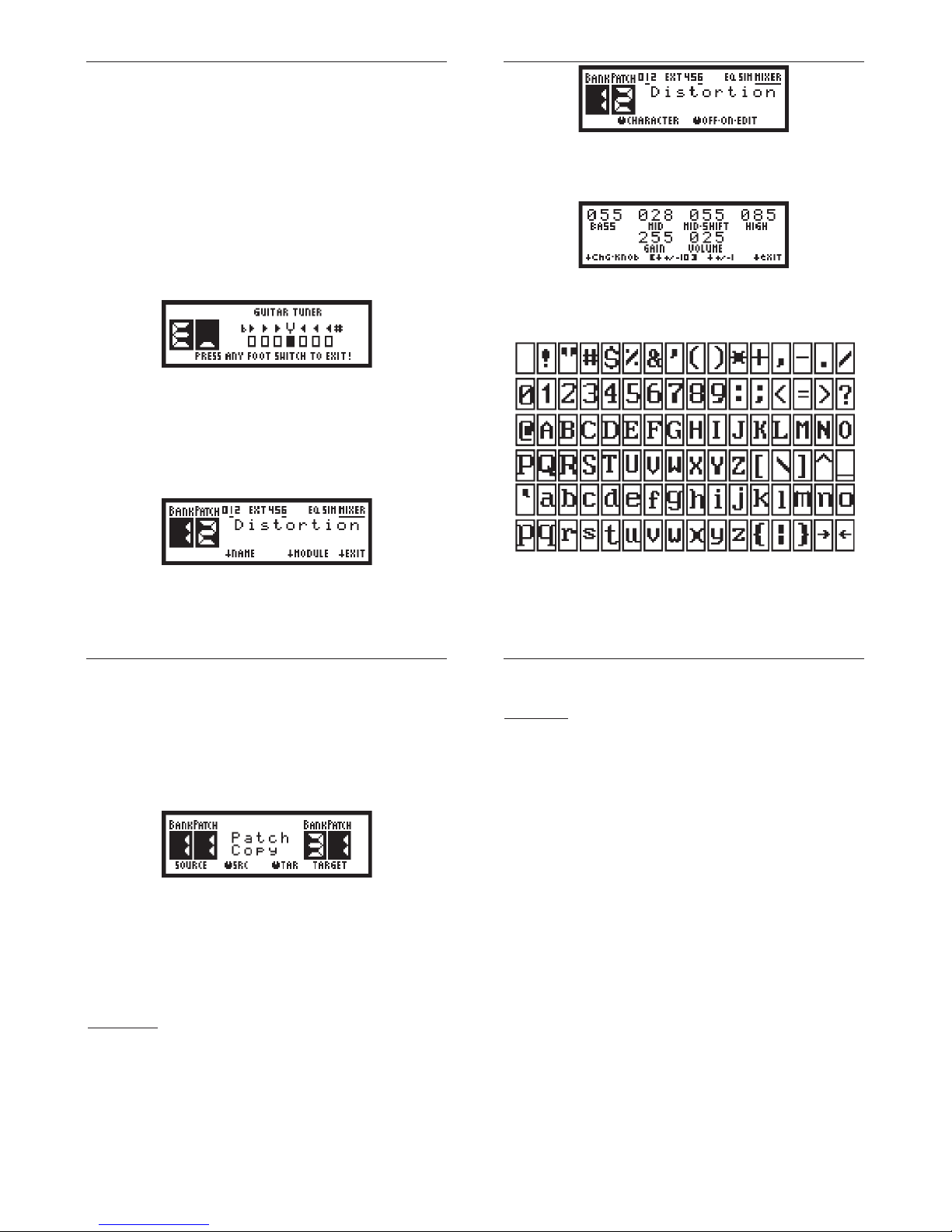
Understand the Useful Information on LCD
Patch-Mode
When you step 1 of 5 foot-switches, a patch is engaged and LCD shows below information:
Below information is shown when the patch is disengaged.
(Step the same foot-switch again)
(1) Analog Sound Module Icon
Numerical icon (0 to 9): Icons turned on indicate their corresponding sound module slot installed
with analog sound module.
EXT icon: External loop for external effect pedal.
EQ icon: Onboard analog sound module “7-Band Global Equalizer”.
1
2
3
4
1
2
3
4
_______________________________________________________________________________________
7
SIM icon: Onboard analog sound module “Speaker Simulator”.
MIXER icon: Onboard analog sound module “Stereo Mixer”.
Underline icon: Indicates the corresponding analog sound module turned on.
(2) Patch Name
Displays the name of current patch engaged. If no patch engaged, message “No Patch Engaged”
shown.
(3) Corresponding Function of 4 Rotate-Press Knobs
Rotate the knob clockwise or anticlockwise to adjust corresponding setting value.
ĻPress the knob to select corresponding function.
(4) Bank/Patch Icon
Bank: Current bank of sound setting storage.
Patch: Current patch inside current bank, a dash mark “ņ“ indicates there is no patch engaged.
Pedal-Mode
Pedal-Mode allows player to have much more flexibility to take control of ON/OFF state of all
onboard sound modules and plug-in modules. Each Patch has its own pedal-mode settings. Player
can program each foot-switch to match up with any installed module.
(1) Foot-Switch & Module Number
Display what sound module is currently matched to the engaged foot-switch.
(2) Analog Sound Module Icon
Numerical icon (0 to 9): Icons turned on indicate their corresponding sound module slot installed
with analog sound module.
EXT icon: External loop for external effect pedal.
1
2
3
4
5
_______________________________________________________________________________________
8
EQ icon: Onboard analog sound module “7-Band Global Equalizer”.
SIM icon: Onboard analog sound module “Speaker Simulator”.
MIXER icon: Onboard analog sound module “Stereo Mixer”.
Underline icon: Indicates the corresponding analog sound module turned on.
(3) Module Name
Shows current module that is ON or OFF when a foot-switch is stepped.
(4) Pedal-Mode Icon
This blinking icon will appear when Pedal-Mode is activated.
(5) Corresponding Function of 4 Rotate-Press Knobs
Rotate the knob clockwise or anticlockwise to select which module to be matched to your
preferred foot-switch.
ĻPress knob1 to edit module setting, or press knob2 to confirm foot-switch & module
matching and then exit pedal-mode setting.
Bank/Patch/Pedal-Mode Switching
Patch-Mode
Under the normal LCD manual display mode, you can step any foot switch whenever you want to
engage a sound patch. This action will call out a group of settings (tone parameters and module
chain’s on/off state) of analog sound modules from AGP-1 system memory. Step the same foot
switch again to disengage the current patch. Step foot-switch 3 & 4 simultaneously for bank down
or step foot switch 4 & 5 for bank up.
Pedal-Mode
When there is a patch engaged, step foot-switch 2 & 3 simultaneously to activate Pedal-Mode.
Step any one of five foot-switches to toggle ON/OFF of its corresponding module (assigned by
user). Step foot-switch 2 & 3 again to exit Pedal-Mode and go back to previous patch number.
Enable/Disable Onboard Speaker Simulator
Under the normal LCD manual display mode, press parameter knob 1 to enable/disable the
Speaker Simulator. The Speaker Simulator is very useful for standalone guitar sound recording or
mixed sound recording (both backing music and guitar sound) without the use of microphone to
pickup the sound from speaker cabinet or guitar power amplifier. It is also a cool feature that the
user can connect AGP-1 output directly to PA system for practice or onstage show.
_______________________________________________________________________________________
9
Enable/Disable Onboard Mixer
Under the normal LCD manual display mode, press parameter knob 2 to enable/disable the Mixer.
Enable/Disable Onboard Metronome
Under the normal LCD manual display mode, press parameter knob 3 to enable/disable the
metronome. If metronome enabled, rotate parameter knob 3 to adjust the tempo speed or rotate
the parameter knob 4 to change the beat. Please note that the metronome tone will only go to True
Bypass Output when Mixer is enabled.
Enable/Disable EXT LOOP
During the sound patch setting, you can enable/disable EXT LOOP to make an additional external
guitar effect pedal connected or not connected in series with analog sound modules chain.
Tuning Your Guitar using Built-in Tuner
Step foot-switch 1 & 2 simultaneously to enter guitar tuner mode.
Play a single open note on the string being tuned, then a corresponding note name closest to the
pitch of the plucked string appears on LCD. During the tuning, the small rectangular icon will move
to left or right to indicate the played string pitch that is too high or too low. The string is in tune when
the small rectangular icon moves to center. Step any foot switch to exit when guitar tuning done.
Create, Edit and Save Your Own Sound Settings
1. Select your preferred Bank and Patch by stepping corresponding foot switch.
2. Press “SETUP” knob to enter sound patch edit mode.
_______________________________________________________________________________________
10
3. Press “MODULE” knob to select your preferred analog sound module, the corresponding
analog sound module name will be shown on LCD.
4. Rotate “OFF-ON-EDIT” knob to enable/disable the installed analog sound module or edit the
analog sound module settings.
5. Inside the sound module setting manual display, rotate the corresponding knob to adjust sound.
6. Press “+/- 10” or “+/- 1” knob to switch between Ten Increment/Decrement and One
Increment/Decrement.
7. Press “Chg.knob” to switch to other group of sound parameter control knobs.
8. Press “exit” knob to save your sound module settings and exit.
9. Repeat 3 to 8 for other analog sound module setting.
Characters Map
_______________________________________________________________________________________
11
10.Go to next step if you want to assign or edit patch name, otherwise press “EXIT” knob to save
all settings and exit.
11.Press “NAME” knob to switch to patch name edit mode.
12.Rotate “CHARACTER” knob to change the character, and then press this knob to confirm
current character and go for next character input.
13.Press “EXIT” to quit the edit mode, and all analog sound module settings and patch name will
be saved.
Patch Copy
With this useful function, you can move your predefined patch to wherever you want.
1. Make sure there is no patch engaged, then press “SETUP” knob to enter “Patch Copy” mode.
2. Rotate “SRC” knob to select source Bank/Patch.
3. Rotate “TAR” knob to select target Bank/Patch.
4. Press “Run” knob to copy source Bank/Patch settings into target Bank/Patch.
5. Press “EXIT” knob to exit “Patch Copy” mode.
Onboard and Plug-in Analog Sound Modules
There are two kinds of analog sound module: onboard module and plug-in module.
Onboard Modules
(1) 7-Band Global Equalizer
100Hz to 6.4KHz: adjust to boost or cut the corresponding frequencies.
VOLUME: set the output level.
(2) Speaker Simulator
The Speaker Simulator is very useful for standalone guitar sound recording or mixed sound
recording (using built-in mixer to mix both backing music and guitar sound) without the use of
microphone to pickup the sound from speaker cabinet or guitar power amplifier. It is also a cool
feature that the user can plug AGP-1 output directly to PA system for practice or onstage show.
_______________________________________________________________________________________
12
(3) Mixer
Mix the external audio, metronome tone and guitar signal together. Four control knobs are reserved
for the control of metronome volume, guitar balance, external signal level and master volume.
Plug-in Modules
(1) Compressor/NoiseGate
The Compressor/Noisegate divides the input signal into three portions.
|------1------|noisegate |------2------|rotation |------3------|
When the signal is smaller than noisegate (in portion 1), it will be cut and removed.
When signal is in between noisegate and rotation (in portion 2), it will be amplified with appropriate
gain to maintain smooth volume.
When signal is larger than rotation (in portion 3), it will be suppressed to maintain steady volume.
The use of Compressor/Noisegate module may be a bit complicated when compared with other
modules. Please follow below steps to get your preferred tone.
(a) Turn off all other modules. Only Compressor/Noisegate is ON.
(b) In the beginning, set Gain to 0, Noisegate to 255, Compression to 0, Rotation to 0.
(c) Use your finger to punch the guitar high E string (high frequency E) slightly and keep decreasing
(set to one decrement) Noisegate value. When you just hear string "clicking" noise, then stop
decreasing Noisegate value. This Noisegate value is your preferred triggering level of guitar input
signal.
(d) Set Compression value to 255. Strum guitar strings and increase Rotation value till you hear the
guitar sound volume that is getting louder rapidly. This Rotation value is the upper limit of signal
input. Any signal over this rotations point will be suppressed to maintain a steady guitar volume
output.
(e) For most of case, setting gain value to 0 is good enough. You are better not to set the value
over 5. Any values bigger than 5 are used for some small sensitive guitar pickup or other kind of
small signal input.
(f) Now you can set the Compression value to any value in between 0 to 255. Bigger value will have
longer guitar signal sustain. Bigger value will also have noise louder when guitar signal is getting
weak.
(g) You can repeat (c) to (f) to refine your settings.
(2) Overdrive
DRIVE: set signal gain.
TONE: set your preferred tone color, middle value 128 will filter both higher & lower frequencies
evenly. When the value is more close to 255, Tone control works more like a high-pass filter. When
the value is more close to 0, Tone control works more like a low-pass filter.
VOLUME: set output volume.

_______________________________________________________________________________________
13
(3) Metal Distortion
BASS: set the low frequencies.
MID: set the middle frequencies.
MID-SHIFT: "Mid" control knob acts as a band-pass filter. “Mid-Shift” will shift the band-pass filter to
lower portion or higher portion of frequencies. This design can cover almost full band of middle
frequencies filtering with minimum numbers of control knob. You should set “Mid-Shift” value to fix
your preferred middle frequencies band first and then set “Mid” to refine the middle frequencies.
HIGH: set the high frequencies.
GAIN: set signal gain/distortion.
VOLUME: set output volume.
(4) Chorus
SPEED: set signal vibration speed
DEPTH: set the level of signal vibration.
TONE: adjust to have more or less high frequencies.
MIX.BAL: adjust to have more or less chorus effect.
(5) Flanger
SPEED: set signal vibration speed
DEPTH: set the level of signal vibration.
MANUAL: set the offset of depth.
FEEDBACK: adjust to have more or less signal feedback into input.
(6) Delay/Echo/Reverb
TIME: set time delay value
BLEND: adjust to have more or less mixed effect.
REPEAT: adjust to have more or less delayed signal going back to input.
(7) Acoustic Simulator
LEVEL: set output volume.
BODY: set the amount of bass frequencies.
MIDDLE: set the amount of middle frequencies.
TOP: set the amount of high frequencies.
MODE: four hardware preset modes – STANDARD, JUMBO, ENHANCE, PIEZO.
(8) Auto-Wah
SENS: set the response to the change of input picking signal.
MANUAL: move the frequencies pass-band to be lower or higher.
LPF/WAH: move to LPF (Low-Pass Filtering) to cut more high frequencies, or move to WAH to act
as conventional auto-wah (cuts both low and high frequencies).
LEVEL: set the output volume.
_______________________________________________________________________________________
14
(9) Hot Distortion
DRIVE: set the signal gain.
TONE: adjust to have more low frequencies or high frequencies.
VOLUME: adjust output volume.
(10) Fuzz
SUSTAIN: adjust the sound from weak to hard edged fuzz.
TONE: adjust to have more low frequencies or high frequencies.
VOLUME: adjust output volume.
(11) Phaser
SPEED: set signal vibration speed.
DEPTH: set the level of signal vibration.
MANUAL: set the offset of depth.
FEEDBACK: adjust to have more or less signal feedback into input.
(12) Octaver
2OCT.DOWN: set amount of second lower octave signal.
1OCT.DOWN: set amount of first lower octave signal.
NORMAL: set amount of direct signal.
1OCT.UP: set amount of first upper octave signal.
(13) Tremolo
RATE: set the speed of signal amplitude variation.
DEPTH: set the range of signal amplitude variation.
WAVE: set to 0 to have triangular wave modulation (smooth signal amplitude variation), or set to
255 to have square wave modulation (rapid amplitude variation).
Install/Uninstall or Rearrange Your Analog Sound Modules
There are total 10 module slots on AGP-1. All analog sound modules are plugged into these 10
slots which are configured like standard effect pedal chain. You can rearrange the sound modules
plug-in position to obtain many thousand of combinations and sound effects.
Guitar Signal Flow
_______________________________________________________________________________________
15
Analog Sound Modules
Recommendations of module position:
(1) Compressor/NoiseGate – first slot.
(2) Octaver – first or second slot.
(3) Acoustic Simulator – front end slot(s).
(4) Overdrive – front end slot(s).
(5) Distortion – front end slot(s).
(6) Hot Distortion – front end slot(s).
(7) Fuzz – front end slot(s).
(8) Auto-Wah – a slot after high gain module (overdrive, distortion or fuzz).
(9) Chorus – middle slot(s).
(10) Flanger – middle slot(s).
(11) Phaser – middle slot(s).
(12) Delay/Echo/Reverb – back end slot(s).
(13) Tremolo – the last slot or back end slot(s).
Bottom view of AGP-1 with case opened
_______________________________________________________________________________________
16
Follow below steps to install/uninstall or rearrange sound module positions:
(1) Referring to “Panel View Diagram”, loosen and remove all 16 pieces of screw and open the
case.
(2) To unplug the module, just simply hold the module board edge with two fingers and then pull out
genteelly.
(3) To plug the module, please be careful that all pins in sound module should be exactly matched
to the correct position in slot, upper group of pins connected to upper group of receptacles and
module pin 1 connected to receptacle pin 1.
(4) Repeat step 2 & 3 to rearrange any other sound module’s plug-in position.
(5) Close the case and put on all 16 screws.
Update the Firmware and Check Firmware Version
1. Unplug the DC plug.
2. Connect serial cable to PC and AGP-1 COM port.
3. Press and hold the parameter knobs 1, 2 & 4.
4. Plug the DC plug.
5. AGP-1 goes into firmware update mode. There will be a current firmware version shown on
LCD screen.

_______________________________________________________________________________________
17
6. Press “YES” to continue the firmware update or press “NO” to exit.
7. Under Windows environment, run the program “Hyper Terminal”
(StartĺProgramsĺAccessoriesĺCommunicationsĺHyper Terminal).
8. Inside the “Port Settings” popup window, set the COM port as below:
Bits per second:9600 Data bits:8 Parity:None Stop Bits:1 Flow control:None
9. In the pulldown manual, select “TransferĺSend File”. Select transmission protocol “Xmodem
(don’t select 1K Xmodem)”. Browse the firmware file directory and select the firmware file.
_______________________________________________________________________________________
18
10. Press the “YES” knob on processor.
11. The processor will try to establish a connection with PC.
12. Click the “Send” icon on “Send File” window.
13. When success in making connection with PC, processor will erase the program memory and
proceed the firmware updating.
_______________________________________________________________________________________
19
14. Now the processor is updating the firmware, please don’t turn off the power.
15. When firmware update completed, the system will restart.
16. If connection loss happened, the system will stop the updating. You have to restart from step 1
to repeat the whole process.
_______________________________________________________________________________________
20
What This Product Includes
(1) AGP-1 x1
(2) Value Pack: Analog Sound Module x3
Standard Pack: Analog Sound Module x6
Deluxe Pack: Analog Sound Module x10
(3) Power Adapter x1
(4) RS-232 Cable x1
(5) Owner’s Manual x1
Copyright © 2009-2012 Tech-in-Mind Electronics
All rights reserved. No part of this publication may be reproduced in
any form without the permission of Tech-in-Mind Electronics.
Popular Music Pedal manuals by other brands

EarthQuaker Devices
EarthQuaker Devices Tentacle Operation manual

Rainger FX
Rainger FX Dr FREAKENSTEIN DWARF user manual

Electro-Harmonix
Electro-Harmonix Octavix manual

OtalgiaFX
OtalgiaFX MOSFET BOOST Build guide

TC-Helicon
TC-Helicon MIC MECHANIC 2 user manual

Shift Line
Shift Line A+ Prism II quick start guide

Accel
Accel DD-SS Digital Delay user guide

Malekko
Malekko Charlie Foxtrot user manual

Radial Engineering
Radial Engineering Hot-British V9 user guide

Behringer
Behringer HI BAND FLANGER HF300 quick guide

HELIX
HELIX HEXPBA02 User guide & installation manual

Demonic Machines
Demonic Machines Hulk Booster manual


