HELIX HEXPBA02 Instruction Manual

32 FORD PEDAL ASSEMBLY
HEXPBA02
User Guide & Installation Manual
TECH SUPPORT: 503.693.1918 WWW.HELIXSUSPENSION.COM
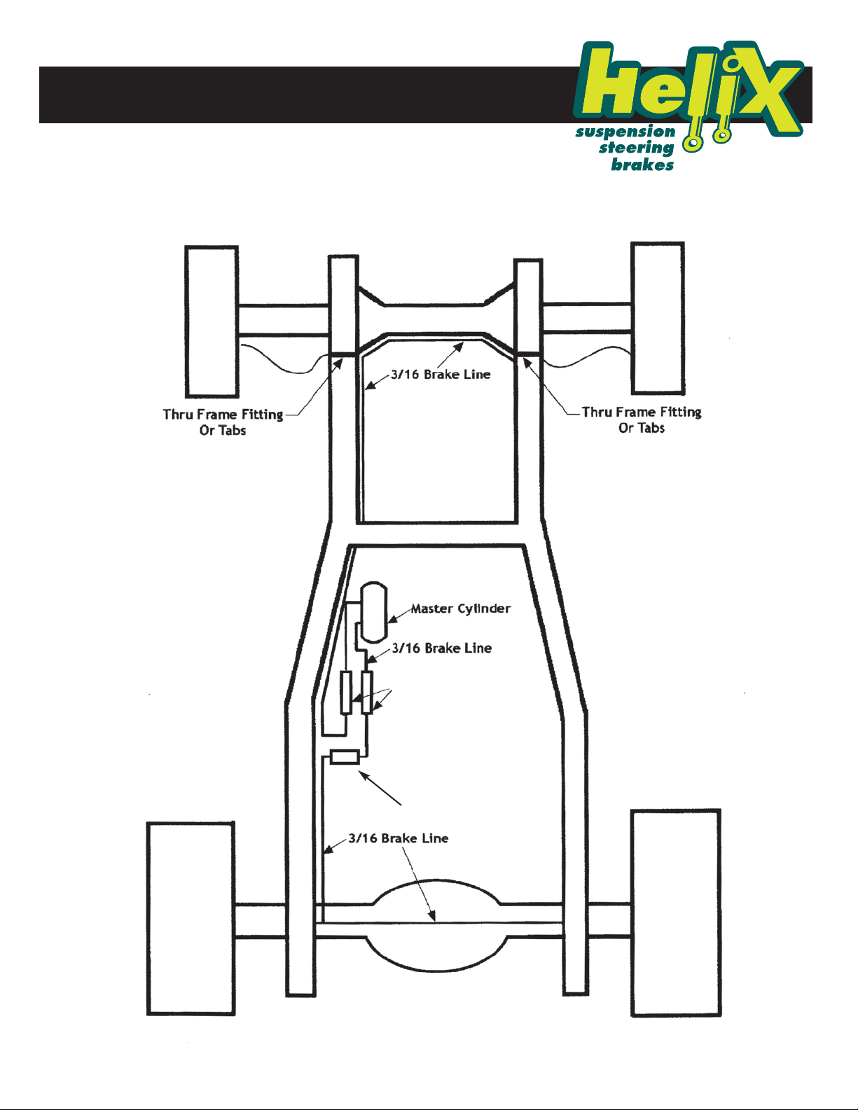
The master cylinder is suitable for 4-wheel disc or disc/drum brake setups. The bracket can be bolted or
welded to the left frame rail (boxed or stock).
The selection and installation of brake components should only be done by experienced professionals in the
proper installation and operation of braking systems. The installer must use his/her own discretion to
determine the suitability of the brake components and brake kits for every particular application.
1.) Pick a location that best lines up with a proper brake pedal location. The brake pedal mount can be bolted in or welded in on either
a channeled or a boxed frame rail. This kit is supplied with the correct hardware to bolt it into a channeled frame. If you are using a
boxed frame you will need to supply the correct hardware. Try to keep the master cylinder mounted as level as possible. When selecting
a pedal location you will need to make sure you have enough pedal travel. Make sure the pedal will bottom out the master cylinder
before the pedal touches the floor. Total pedal travel should be about 5 1/2”. The pedal can be bent or modified for driver comfort but
avoid shortening the height of the pedal as this will result in increased pedal effort.
2.) Assemble the master cylinder to the brake pedal frame mount with the 3/8"-16 x 1-1/2" bolts, washers and nylock nuts. Torque
these to 18-24 ft. lbs. Assemble the brake pedal on to the brake pedal frame mount. Install the clevis on to the brake pedal and adjust
the pedal location so the center of the clevis pin is 1/2" forward from the center line of the brake pedal pivot.
3.) The push rod can now be cut to the correct length. NOTE: REMOVE THE RETAINING CLIP ON THE PUSH ROD WHILE MOCKING UP
YOUR INSTALLATION. Measure for the correct push rod length and cut it making sure you have a minimum of 1/2" of engagement in
the clevis.
4.) Once you have determined the correct location of the brake bracket, mark and drill the two 1/2" mounting holes in your frame and
bolt it into position with the two 1/2" bolts, washers and nylon lock nuts supplied. Torque these to 38-57 ft. lbs.
5.) Mark the location and angle of the pedal pad and weld the brake pedal pad mount to the brake pedal.
6.) Reinstall the retaining clip on the push rod and install it in the master cylinder piston. With the pedal returned to its non-depressed
position adjust the push rod plunger so there is slight free play between the plunger and the piston on the master cylinder.
7.) The brake pedal should be free to return when no pressure is applied, allowing the master cylinder push-rod to return to its
non-depressed position. Any preload will not allow the hydraulic system to function properly.
In some cases the master cylinder spring (internal) may not be strong enough to fully return the push rod; in this case an additional pedal
return spring can be used. When using an additional return spring the pedal should have an adjustable return stop on it. This will stop
the piston from excessively banging the snap ring located under the rubber boot on the master cylinder. Adjust the stop so the pedal
stops returning at the point when the master cylinder piston retracts against the snap ring.
©2016 The Hoffman Group L.L.C. All rights reserved.HEXPBA02 6/14/2016 Page 1 of 6
The above instructions are for reference only. THG LLC is not responsible for any inaccuracies in the above instructions. THG LLC is also not responsible for any property damage orpersonal injuries resulting from the
above instructions. Installation by qualified automotive professionalsis highly recommended.1
WARNING
8.) The reservoir closest to the plunger is the front reservoir and gets routed to both front brakes. The rear reservoir is routed to both rear
brakes. If the master cylinder reservoir level is mounted lower that the horizontal plane of the brake calipers a residual check valve will
have to be mounted in line as close to the master cylinder as possible to prevent fluid drain back. A two pound residual check valve is
used for disc brakes and a ten pound is used for drum brakes. An adjustable proportioning valve should be plumed in the rear line to
adjust the front to rear brake bias.
9.) Install the hydraulic brake lines using 3/16" hard lines. Attention must be made to the routing and location of the hydraulic brake
lines. Avoid any heat sources such as exhaust pipes. Install new flex lines making sure you check that the lines have clearance through
the entire suspension travel and turning radius.
10.) Remove the master cylinder and bench bleed it following the attached instructions for bench bleeding. Reinstall the master cylinder,
connect the lines and bleed the entire system per the attached bleeding instructions.
11.) Before operating the vehicle, test the brakes under controlled conditions. Make several stops in a safe area from low speeds,
gradually working up to operating speeds.
12.) Adjust the front to rear brake bias following the instructions supplied with your proportioning valve.

1.) Pick a location that best lines up with a proper brake pedal location. The brake pedal mount can be bolted in or welded in on either
a channeled or a boxed frame rail. This kit is supplied with the correct hardware to bolt it into a channeled frame. If you are using a
boxed frame you will need to supply the correct hardware. Try to keep the master cylinder mounted as level as possible. When selecting
a pedal location you will need to make sure you have enough pedal travel. Make sure the pedal will bottom out the master cylinder
before the pedal touches the floor. Total pedal travel should be about 5 1/2”. The pedal can be bent or modified for driver comfort but
avoid shortening the height of the pedal as this will result in increased pedal effort.
2.) Assemble the master cylinder to the brake pedal frame mount with the 3/8"-16 x 1-1/2" bolts, washers and nylock nuts. Torque
these to 18-24 ft. lbs. Assemble the brake pedal on to the brake pedal frame mount. Install the clevis on to the brake pedal and adjust
the pedal location so the center of the clevis pin is 1/2" forward from the center line of the brake pedal pivot.
3.) The push rod can now be cut to the correct length. NOTE: REMOVE THE RETAINING CLIP ON THE PUSH ROD WHILE MOCKING UP
YOUR INSTALLATION. Measure for the correct push rod length and cut it making sure you have a minimum of 1/2" of engagement in
the clevis.
4.) Once you have determined the correct location of the brake bracket, mark and drill the two 1/2" mounting holes in your frame and
bolt it into position with the two 1/2" bolts, washers and nylon lock nuts supplied. Torque these to 38-57 ft. lbs.
5.) Mark the location and angle of the pedal pad and weld the brake pedal pad mount to the brake pedal.
6.) Reinstall the retaining clip on the push rod and install it in the master cylinder piston. With the pedal returned to its non-depressed
position adjust the push rod plunger so there is slight free play between the plunger and the piston on the master cylinder.
7.) The brake pedal should be free to return when no pressure is applied, allowing the master cylinder push-rod to return to its
non-depressed position. Any preload will not allow the hydraulic system to function properly.
In some cases the master cylinder spring (internal) may not be strong enough to fully return the push rod; in this case an additional pedal
return spring can be used. When using an additional return spring the pedal should have an adjustable return stop on it. This will stop
the piston from excessively banging the snap ring located under the rubber boot on the master cylinder. Adjust the stop so the pedal
stops returning at the point when the master cylinder piston retracts against the snap ring.
32 FORD PEDAL ASSEMBLY
HEXPBA02
User Guide & Installation Manual
TECH SUPPORT: 503.693.1918 WWW.HELIXSUSPENSION.COM
©2016 The Hoffman Group L.L.C. All rights reserved.HEXPBA02 6/14/2016 Page 2 of 6
The above instructions are for reference only. THG LLC is not responsible for any inaccuracies in the above instructions. THG LLC is also not responsible for any property damage orpersonal injuries resulting from the
above instructions. Installation by qualified automotive professionalsis highly recommended.2
8.) The reservoir closest to the plunger is the front reservoir and gets routed to both front brakes. The rear reservoir is routed to both rear
brakes. If the master cylinder reservoir level is mounted lower that the horizontal plane of the brake calipers a residual check valve will
have to be mounted in line as close to the master cylinder as possible to prevent fluid drain back. A two pound residual check valve is
used for disc brakes and a ten pound is used for drum brakes. An adjustable proportioning valve should be plumed in the rear line to
adjust the front to rear brake bias.
9.) Install the hydraulic brake lines using 3/16" hard lines. Attention must be made to the routing and location of the hydraulic brake
lines. Avoid any heat sources such as exhaust pipes. Install new flex lines making sure you check that the lines have clearance through
the entire suspension travel and turning radius.
10.) Remove the master cylinder and bench bleed it following the attached instructions for bench bleeding. Reinstall the master cylinder,
connect the lines and bleed the entire system per the attached bleeding instructions.
11.) Before operating the vehicle, test the brakes under controlled conditions. Make several stops in a safe area from low speeds,
gradually working up to operating speeds.
12.) Adjust the front to rear brake bias following the instructions supplied with your proportioning valve.

32 FORD PEDAL ASSEMBLY
HEXPBA02
User Guide & Installation Manual
TECH SUPPORT: 503.693.1918 WWW.HELIXSUSPENSION.COM
©2016 The Hoffman Group L.L.C. All rights reserved.HEXPBA02 6/14/2016 Page 3 of 6
The above instructions are for reference only. THG LLC is not responsible for any inaccuracies in the above instructions. THG LLC is also not responsible for any property damage orpersonal injuries resulting from the
above instructions. Installation by qualified automotive professionalsis highly recommended.3
Bench Bleeding The Mast Cylinder
NOTE: "Bench bleeding" (removing air from the master cylinder) must be completed BEFORE the replacement unit is installed in the
vehicle. Otherwise, the brake pedal will be insufficient and THE WARRANTY WILL BE VOID!
1.) Position the replacement master cylinder in a vise so that the jaws clamp onto the mounting flange. DO NOT TIGHTEN THE VISE
JAWS ON THE MASTER CYLINDER BODY! This will cause damage and void the warranty.
2.) Install brake failure warning switch and proportioning valve, if so equipped, onto the replacement master cylinder BEFORE bench
bleeding the unit. Use the new o-rings supplied with the replacement unit on the valves and switch. Install plugs in the proportioning
valve ports, if so equipped, before bench bleeding.
3.) Install bleeder tubes, if available, into the brake line outlet ports or use plugs to seal the ports.
4.) Add enough clean brake fluid to the reservoir so that the bleeder tube ends are submerged beneath the fluid level.
5.) Use a wooden dowel or similar tool to slowly push the master cylinder piston in about one inch, then release the piston slowly.
CAUTION: Be careful to avoid spraying brake fluid! Keep your face away from the open reservoir.
6.) Wait 15 seconds and repeat step 5 until you no longer see air bubbles in the reservoir.
7.) Replace the reservoir cover. Do not remove bleeder tubes from the brake line fittings yet.
NOTE: Some fluid around the mouth of the piston bore is normal and does not indicate leakage. This is a rust inhibitive bore lubricant
used during assembly.

32 FORD PEDAL ASSEMBLY
HEXPBA002
User Guide & Installation Manual
TECH SUPPORT: 503.693.1918 WWW.HELIXSUSPENSION.COM
©2016 The Hoffman Group L.L.C. All rights reserved.HEXPBA02 6/14/2016 Page 4 of 6
The above instructions are for reference only. THG LLC is not responsible for any inaccuracies in the above instructions. THG LLC is also not responsible for any property damage orpersonal injuries resulting from the
above instructions. Installation by qualified automotive professionalsis highly recommended.4
Bleeding The Lines
1.) Remove the master cylinder cover and check the fluid level. Be sure to check the fluid level often during the bleeding process. And
add fluid as necessary to prevent air from entering the master cylinder. If this happens you MUST start over at bench bleeding the master
cylinder.
2.) Replace the master cylinder cap.
3.) The use of our speed bleeders will allow you to perform this job by yourself by simply cracking the speed bleeder enough to allow
fluid to be forced through. The speed bleeder has an internal check valve that prevents fluid from returning into the caliper once the
pedal is released. This removes the necessity of closing the bleeder screw before the pedal is released, allowing one person to bleed the
brakes. Otherwise you will need an assistant to pump the brake pedal while you open and close the bleeder screws at the appropriate
times during this process.
4.) The wheel farthest away from the master cylinder is bled first which in most cases is in this order: Right rear, left rear, right front and
left front. Failure to bleed in the proper order will cause air to remain in the lines.
5.) It may be necessary to remove the calipers from the caliper brackets while leaving the hoses attached. The calipers must be oriented
in such a way as to ensure the bleeder screws point up.
If you bleed the calipers while mounted on the rotors, air may become trapped inside the caliper reservoir and bleeding will be unsuc-
cessful. The caliper should be oriented in such a way as to allow air inside the calipers internal reservoir to escape. Sometimes this
means the bleeder screw is pointing straight up and sometimes it is at a bit of an angle. It is recommended that you do not allow the
caliper to hang from the brake hose. Instead use a piece of wire to position the calipers correctly. Otherwise damage to the brake hoses
may result. If you find it necessary to remove the calipers from the rotor, be certain to insert a block of wood that is approximately the
same thickness as the rotor between the brake pads to prevent the caliper pistons from being pushed out of the caliper.
6.) Crack the bleeder screws at the appropriate wheel just enough to make it easy to loosen later. Attach a length of 3/16” clear plastic
tube to the end of the bleeder screw. Submerge the other end of the tube into a container filled with brake fluid.
7.) Crack the bleeder screw open just enough to allow fluid to leave the valve and have an assistant slowly and firmly apply pressure to
the pedal. Have the assistant hold pressure on the pedal until you see no more air bubbles coming out of the hose. Close the bleeder
screw and have the assistant release the brake pedal. Repeat this step until no more air is seen leaving the tube.
8.) Proceed to the next wheel in the bleeding order and repeat steps 6 & 7 for each. Be sure to check the fluid level in the master
cylinder frequently.
9.) Refill the master cylinder to the appropriate level when finished with the entire bleeding process.
10.) Check the pedal, it should feel solid when depressed with no sponginess and should hold under constant pressure without
dropping. If you still have a spongy pedal, repeat the entire process.
11.) Before operating the vehicle test the brakes under controlled conditions. Make several stops in a safe area from low speeds
gradually working up to operating speeds.

32 FORD PEDAL ASSEMBLY
HEXPBA02
User Guide & Installation Manual
TECH SUPPORT: 503.693.1918 WWW.HELIXSUSPENSION.COM
©2016 The Hoffman Group L.L.C. All rights reserved.HEXPBA02 6/14/2016 Page 5 of 6
The above instructions are for reference only. THG LLC is not responsible for any inaccuracies in the above instructions. THG LLC is also not responsible for any property damage orpersonal injuries resulting from the
above instructions. Installation by qualified automotive professionalsis highly recommended.5
Most Common Problems
1.) The bleeder screws on the calipers are not facing up.
2.) The master cylinder was not bench bled or was not bled completely.
3.) Defective rebuilt master cylinder with pitted cylinder bore or defective seals.
4.) Master cylinder bore size too small for system volume requirements.
5.) Master cylinder mounted lower than the calipers or wheel cylinders.
6.) Lines or components near a heat source.
7.) Low drag metric calipers without the use of a quick take up master cylinder.
8.) No residual valve to rear drums.
9.) Drum brake wheel cylinders too large.
10.) Use of Silicone brake fluid.
11.) Rear caliper parking / pistons not set up properly with a rear disc system.
12.) Rear calipers not being bled properly. Most four wheel disc brake problems come from the rear.
13.) Improper pedal adjustment with too much play.
14.) Old or inferior quality brake hoses.
How To Properly Diagnose A Brake Problem
If you have very poor brakes, a spongy pedal or no pedal at all you will have to do some diagnostics to determine where the problem is
in your system. Is it the master cylinder, the front brakes or the rear brakes?
These tests assume that your system is properly installed and bled. Perform these simple tests to find where the problem is. Once you
know where the problem is it will much easier to fix.
1.) Disconnect the brake lines from the master cylinder while leaving it on the vehicle.
2.) Obtain solid tapered plugs for the master cylinder outlets with the correct thread pitch.
3.) Plug the master cylinder outlets. Step on the pedal and hold pressure for about 30 seconds. If the
pedal remains firm then the master cylinder is good. If the pedal sinks to the floor then the master
cylinder is bad.
4.) If the master cylinder is fine, connect the line to the front brakes. If the pedal remains firm then
the problem is not coming from the front brakes. If the pedal sinks to the floor or is excessively
spongy then the problem is with the front brakes.
5.) Connect the rear line and if the pedal goes bad then the problem is in the rear. You may also
check whether your lack of a pedal comes from the front or rear this way. If you are sure the master cylinder is good, clamp off the front
rubber hoses and try the pedal. If you get a good pedal then you know the problem is from the front calipers. Be very careful not to
damage the hoses and try to protect them from damage by placing the hose between something smooth. There is a special tool sold in
auto parts stores for this purpose. Try it on the rear if the
front is fine.
IF YOU HAVE A GOOD PEDAL BUT YOUR CAR WILL NOT STOP, YOU MUST OBTAIN PRESSURE READINGS AT THE MASTER
CYLINDER AND THE FRONT AND REAR WHEELS.
Disc brakes minimum pressure 800 PSI
Drum brakes minimum pressure 400 PSI
Proportioning Valve
Residual Valves
2 Lb Disc
10 Lb Drum
32 FORD PEDAL ASSEMBLY
HEXPBA02
Brake Setup
User Guide & Installation Manual
TECH SUPPORT: 503.693.1918 WWW.HELIXSUSPENSION.COM
©2016 The Hoffman Group L.L.C. All rights reserved.HEXPBA02 6/14/2016 Page 6 of 6
The above instructions are for reference only. THG LLC is not responsible for any inaccuracies in the above instructions. THG LLC is also not responsible for any property damage orpersonal injuries resulting from the
above instructions. Installation by qualified automotive professionalsis highly recommended.6
Table of contents
Popular Music Pedal manuals by other brands


Aalberg Audio
Aalberg Audio EKKO EK-1 user manual

Maxon
Maxon ROD880 user guide

Kikusui
Kikusui BIXONIC AXENTRIX A1 user guide

Electro-Harmonix
Electro-Harmonix Andy Summers Walking On The Moon operating instructions

GOODWOOD AUDIO
GOODWOOD AUDIO Bass Interfacer manual

Dunlop
Dunlop Authentic Hendrix ’69 Psych Series quick guide


