DINWAY BAM8 Series User manual

B-
B-
B-
B- 1
1
1
1
Company
Company
Company
Company Profile
Profile
Profile
Profile
Zhejiang Zhiming Electric Imp & Exp Co., Ltd., founded in 2000, is a newly rising group company in Southeast China near Ningbo
port . Up to now, the company has set up 5
5
5
5professional
professional
professional
professional subsidiary
subsidiary
subsidiary
subsidiary companies
companies
companies
companies mainly engaged in manufactur e of low voltage
products including MCB, ELCB, RCBO, SPD, MCCB, distribution box, junction box, AC contactor, starters, relay, pushbutton,
control box, fuse, industrial plugs, switches, CFL lamps, Current transformer, Voltage regulator, voltage stabilizer, Panel meter and
Watt-hour meter and electric accessories such as cable ties and clips, terminal blocks, copper terminals, insulated terminals, cable
glands. We also involved in production some MV and HV production such as vacuum circuit breaker and power transformer.
So
far,
the company has a total 500 employees, many products have also been certified by some international certificates, such
as CE
CE
CE
CE
,
CCC,
CCC,
CCC,
CCC,
PCT,
PCT,
PCT,
PCT,
and
and
and
and KCT
KCT
KCT
KCT
,
SGS
SGS
SGS
SGS
,
CB,
CB,
CB,
CB, SAMKO
SAMKO
SAMKO
SAMKO
,
the annual sales income has reached 38
38
38
38 million US dollars in 2008 ..Our most
products are exported to the former Soviet countries, Europe, Southeast Asia, and South America.
After the past several years
’
operation, the company has won a solid reputation around the world for quality and innovation by
incorporating high-tech technologies in design, development and production. Requirements for reliability, flexibility and simplicity
have always been priorities. Now there are a total of 15
15
15
15 patent
patent
patent
patent products completely designed by ourselves which has possessed
intellectual property. In face of the economic globalization, the company has worked out a plan striving to establish a famous
international brand DINWAY
DINWAY
DINWAY
DINWAY . We sincerely hope to set up long-term business relations and cooperate with friends both at home
and abroad.

B-
B-
B-
B- 2
2
2
2
Conform to IEC 60947-2/EN 60947-2
BAM8
BAM8
BAM8
BAM8 Series
Series
Series
Series
Moulded
Moulded
Moulded
Moulded Case
Case
Case
Case Circuit
Circuit
Circuit
Circuit Breaker
Breaker
Breaker
Breaker
OPERATION
OPERATION
OPERATION
OPERATION INSTRUCTION
INSTRUCTION
INSTRUCTION
INSTRUCTION MANUA
MANUA
MANUA
MANUA
L
Please read the operation instruction mnual before installing and using the product

B-
B-
B-
B- 3
3
3
3
1.
1.
1.
1. Application
Application
Application
Application
BAM8 series moulded case circuit breaker (hereinafter referred to as breaker) is a new type breaker developed by our
company with international advanced technology. It ’ s rated insulation voltage up to 800V. The breaker is mainly used in
distribution netwo rk of AC 50Hz/60Hz, rated voltage up to 690V,rated operating current up to 1250A to distribute electric
power and to protect the line and the equipment from being damaged due to overload, short circuit and under-voltage .It can
also be used for infrequent motor start and for motor overload., short circuit and under-voltage protections.
The circuit breaker, according to its different rated limit short-circuit breaking capacity , is divided into three kinds: S type
(standard type), H type (higher type), R type (limit current type).
The product features small volume, high breaking capacity and short arcing distance so that it is an ideal product for users.
�
The product is in conformity with the standard IEC60947-2.
2.
2.
2.
2. Working
Working
Working
Working conditions
conditions
conditions
conditions
�
Ambient temperature: -5 ℃~+40 ℃; the average temperature within 24h shall not exceed +35 ℃. ( please contact with
us if temperature
at
the mounted site beyond above values)
�
Altitude: The not exceed 2000m
�
Atmosphere condition: At mounting site, relative humidity not exceed 50% at the max temperature of +40 ℃, higher
relative humidity is allowable under lower temperature.
The maximum month-average relative humidity is 90% in the most humid month with a minimum month-average
temperature is +25 ℃. The factor that dew may occur on the product surface due to temperature change shall be taken
into consideration.
�
Pollution grade: Grade III ;

B-
B-
B-
B- 4
4
4
4
3.
3.
3.
3. Type
Type
Type
Type Designation
Designation
Designation
Designation
BA M 8- □ □ □ / □ □ □ □
Type of N-pole for 4-P breaker*
Application: Blank: for power distribution;
2:
for motor protection
Release type and accessory code
Number of poles
Operation mode: Blank: direct operation with handle;
P: motor-driven operation;
Z:
Operation with rotary handle
Code of breaking capacity: S-standard type;
H-higher class type
R-current limiting type
Frame size rated current
Design sequence number
MCCB code
Company code
Note
*:
There are 4 type of N-pole for 4P breaker
�
Without current release components, N-Pole is always
at
making status, not makes and breaks with other three poles;
�
Without current release components, N-Pole makes with other three poles (N-pole first makes then breaks);
�
With current release components, N-Pole makes and breaks with other three poles (N-pole first makes then breaks);
�
With current release components, N-Pole is always
at
making status, not makes and breaks with other three poles;
Table 1. Release mode and Accessory code
Accessory Release mode
Accessory designation
Instantaneous
release
Compound release
No accessory
200
300
Alarm contact
208
308
Shunt release
210
310
Auxiliary contact
220
320
Under-voltage release
230
330
Shunt release, auxiliary contact
240
340
Shunt release, under-voltage release
250
350
Two sets of auxiliary contact
260
360

B-
B-
B-
B- 5
5
5
5
Note: currently there are no breaker type 258 and 358.
4.
4.
4.
4. Main
Main
Main
Main technical
technical
technical
technical parameters
parameters
parameters
parameters
4.1 The split-second response property of the breaker (used for power distribution) is set
at
10In, the split-second response
property of the breaker (used for motor distribution) is set at 12In.
4.2 The rated value of the breaker is shown in table 2.
4.3 The action property of the breaker (used for power distribution) is shown in table 3, and one (used for motor protection) is
in table 4.
Table 2 The rated value of the breaker
Auxiliary contact, under-voltage release
270
370
Shunt release , alarm contact
218
318
Auxiliary contact, alarm contact
228
328
Under-voltage release, alarm contact
238
338
Shunt release, auxiliary contact, alarm contact
248
348
Shunt release, under-voltage release, alarm contact
258
358
Two sets of auxiliary contact, alarm contact
268
368
Auxiliary contact, under-voltage release, alarm contact
278
378
Model
Frame
class
rated
current
Inm A
Reted
current
In A
Rated
voltage
Ue V
Rated
insulation
voltage
Ui V
Rated limit
short circuit
breaking
capacity
Icu kA
415v/690v
Rated limit
short circuit
breaking
capacity Ics
kA
415v/690v
Rated
current of
N pole
BAM8-63S/3P
63
10 16 20 25
32 40 50 63
380/
400/
415
500
15
7.5
BAM8-63S/3P
35
17.5
BAM8-63S/4P
In
BAM8-100S/3P
100
10 16 20 25
32 40 50 63
80 100
380/
400/
415/
690
800
25/3
12.5/1.5
BAM8-100S/2P
50/8
25/4
BAM8-100S/3P
BAM8-100S/4P
=In (If In
≤63A)
=63A(if
In>63A )

B-
B-
B-
B- 6
6
6
6
Table 3 The action property of the over current tripping gear of the breaker (used for power distribution)
Table 4 The action property of the over current release of the breaker (used for motor protection )
BAM8-100S/3P
65/10
32.5/5
BAM8-225S/3P
25
100 125 160
180 200 225
25/5
12.5/2.5
BAM8-225H/2P
50/8
25/4
BAM8-225H/3P
BAM8-225H/4P
=63A(If ≤
125A)
=In/2( if
In>125A )
BAM8-225H/2P
65/10
32.5/5
BAM8-400S/3P
400
225. 250.
315. 350.
400
380/
400/
415/
690
800
35/10
17.5/5
BAM8-400S/4P
In /2
BAM8-400H/3P
50/12
25/6
BAM8-400R/3P
70/15
35/7.5
BAM8-630S/3P
630
400.
500.
630
35/12
17.5/6
BAM8-630S/4P
In /2
BAM8-630H/3P
50/13
25/6.5
BAM8-630R/3P
380/
400/
415
500
70
35
BAM8-800H/3P
800
630 700 800
60
30
BAM8-800R/3P
70
35
BAM8-1250H/3P
1250
700.800
900.1000
1250
65
32.5
No.
Test
current
I/In
Specified time
Initial status
1
Specified no-trip current
1.05
2h (In>63A)
1h (In ≤ 63A )
Cold position
2
Specified trip current
1.30
2h (In>63A)
1h (In ≤ 63A )
Following the test N o.1
No.
Test
current
I/In
Specified time
Initial status
1
Specified no-trip current
1.0
2h
Cold position
2
Specified trip current
1.2
2h
Following the test No.1

B-
B-
B-
B- 7
7
7
7
4.4 The characteristics curve of anti-time limit and the correcting curve of temperature see Fig.1-Fig12.
Characteristic Curve
Fig.1 BAM8-63 (1 0 ~ 32 ), BAM8-100(1 6 ~ 32 ) Fig.2 BAM8-63 (4 0 ~ 63 ), BAM8-100(40 ~ 100 )
Characteristic Curve Characteristic Curve
Fig.3 BAM8-63 (1 0 ~ 32 ), BAM8-100(1 6 ~ 32 ) Fig.4 BAM8-63 (40 ~ 63 ), BAM8-100(40 ~ 100 )
Temperature compensation Curve Temperature compensation Curve

B-
B-
B-
B- 8
8
8
8
Fig.5 BAM8-225 Characteristic Curve Fig.6 BAM8-400 Characteristic Curve
Fig.7 BAM8-225 Temperature compensation Curve Fig.8 BAM8-400 Temperature compensation Curve

B-
B-
B-
B- 9
9
9
9
Fig.9 BAM8-630, 800 Characteristic Curve Fig.10 BAM8-630,800 Characteristic Curve
Fig.11 BAM8-630, 800 Temperature compensation Curve Fig.12 BAM8-630, 800 Temperature compensation Curve
5.
5.
5.
5. Internal
Internal
Internal
Internal accessory
accessory
accessory
accessory and
and
and
and external
external
external
external accessory
accessory
accessory
accessory of
of
of
of breaker
breaker
breaker
breaker
(Internal accessory and external accessory of breaker are installed according to needs of users)
5.1 Internal accessory of breaker
5.1.1 Shunt release
The rated control voltage of the shunt release is AC 50 Hz, 230V and 400V. And DC 24V, 110V,240V. The breaker shall
be reliably switched off under 70%-11% rated voltage.
Note:
Note:
Note:
Note: when
when
when
when the
the
the
the voltage
voltage
voltage
voltage is
is
is
is DC
DC
DC
DC 24V,
24V,
24V,
24V, the
the
the
the current
current
current
current of
of
of
of shunt
shunt
shunt
shunt release
release
release
release must
must
must
must me
me
me
me 5A
5A
5A
5A ±10%A.
10%A.
10%A.
10%A.
B-
B-
B-
B- 10
10
10
10
5.1.2 Under-voltage release
The under – voltage release shall act to switch off the breaker when the power voltage decreases (even if slowly decreases )
to 70% -35% rated voltage .It shall prevent the breaker from reclosing, if the power voltage decreases to less than 35% rated
volta ge .It shall ensure to close the breaker ,if the power voltage is equal to or greater than 85% rated voltage.
The rated voltage of the under-voltage release is 50Hz, 230V and 400V.
Note:
Note:
Note:
Note: only
only
only
only when
when
when
when the
the
the
the under
under
under
under –
–
–
– voltage
voltage
voltage
voltage release
release
release
release be
be
be
be supplied
supplied
supplied
supplied rated
rated
rated
rated voltage,
voltage,
voltage,
voltage, the
the
the
the breaker
breaker
breaker
breaker can
can
can
can be
be
be
be closed,
closed,
closed,
closed, otherwise
otherwise
otherwise
otherwise the
the
the
the
breaker
breaker
breaker
breaker will
will
will
will be
be
be
be damaged
damaged
damaged
damaged .
5.1.3 Auxiliary contact
Auxiliary contact of breaker is divided into two parts. In electricity, each part is not divided. Auxiliary contact (see table 5)
5.1.4 Alarm contact
The rated voltage and related parameters of alarm contact are shown in table
5:
the initial position pf alarm contact are not
changed only when breaker
at
free position or fault tripped.
Table 5 Auxiliary circuit parameter
5.2 External accessory
5.2.1 The motor operation mechanism is shown in table 6 and the max dimension of depth is shown in
table 7.
Table 6
Type
Rated
insulation
Voltage
V
Specifie
d
Heat
Current
A
AC-15
DC-13
Rated
voltage
V
Rated
frequency
Hz
Rated
current
A
Rated
voltage
V
Rated
current
A
Auxiliary
contact
Inm ≤ 225A
400
3
380
50
0.26
220
0.14
Inm ≤ 400A
6
3
0.2
Alarm
contact
3
/
/
/
/
Type
Model
BAM8-63
BAM8-100 BAM8-225
BAM8-400
BAM8-630
BAM8-800
Structure form
Electromagnet
Motor

B-
B-
B-
B- 11
11
11
11
Table7
Note:
Note:
Note:
Note: when
when
when
when the
the
the
the breaker
breaker
breaker
breaker with
with
with
with motor
motor
motor
motor operation
operation
operation
operation mechanism
mechanism
mechanism
mechanism tripped,
tripped,
tripped,
tripped, users
users
users
users must
must
must
must re-set
re-set
re-set
re-set the
the
the
the breaker
breaker
breaker
breaker use
use
use
use motor
motor
motor
motor
operation
operation
operation
operation mechanism
mechanism
mechanism
mechanism before
before
before
before close
close
close
close the
the
the
the breaker.
breaker.
breaker.
breaker.
5.2.2 Rotating handle operation mechanism See Fig. 13 and Table 8
Fig. 13
Table 8
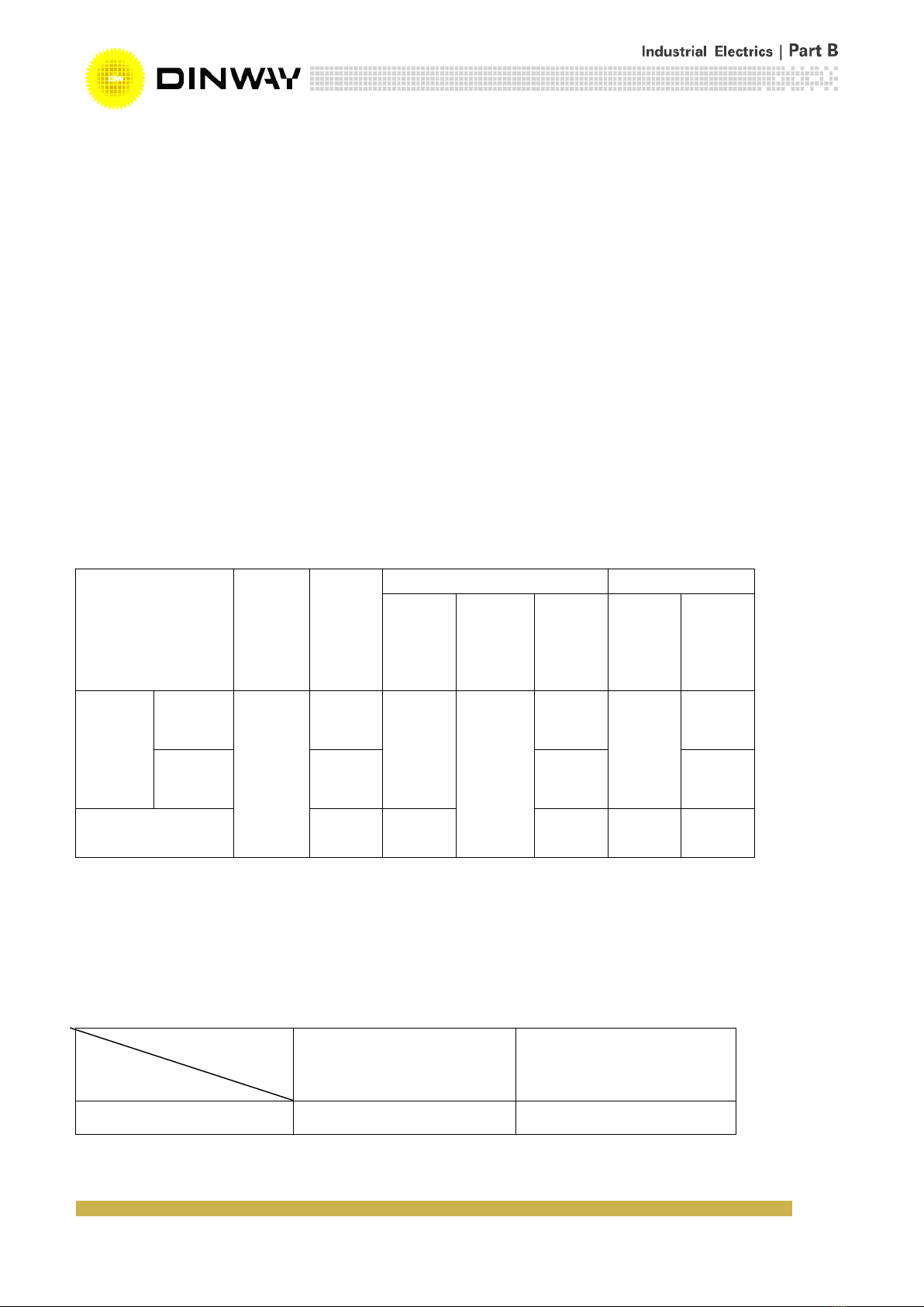
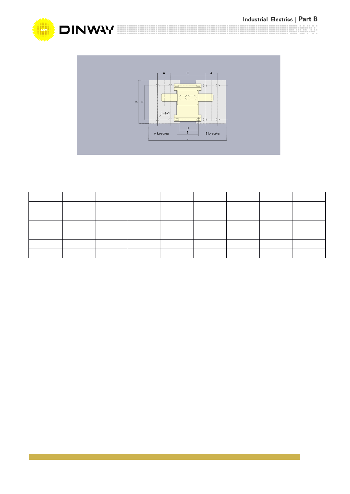
5.2.3 Interlock mechanism is shown in Fig.14 and Table 9.
Voltage specification
50Hz, 220V; 50Hz, 380
DC110V; DC220V
Type
Depth
BAM8-
63S
BAM8-
63H
BAM8-
100S
BAM8-
100H
BAM8-
100R
BAM8-
225S
BAM8-
225H
BAM8-
225R
BAM8-
400S
BAM8-
400H
BAM8-
400R
BAM8-
630S
BAM8-
630H
BAM8-
630R
BAM8-
800H
BAM8-
800R
BAM8-
1 250 H
H
167
175
164
182
195
212
227
230
234
232
290
T
ype
BAM8-63
BAM8-100
BAM8-225
BAM8-
400S
BAM8-400H
BAM8-400R
BAM8-
630S
BAM8-630R
BAM8-800H
BAM8-800R
Dimension H
49
54
54
84
76
83
76
Y
0
0
0
0
-10
0
-20
B-
B-
B-
B- 12
12
12
12
Fig. 14
Table 9
6. Outline and installation dimension
6.1 BAM8-63,100,225 fixed connection outline and installation dimension is shown in Fig. 15a and Table 10.
6.2 BAM8-400,630,800,1250 fixed connection outline and installation dimension is shown in Fig. 15b and Table
11.
6.3 BAM8 series rear connection and plug in connection outline and installation dimension is shown in Fig.16a, Fig.16b,
Fig.17a, Fig.17b, and Table 12.
Model
A
B
C
D
E
F
L
φ d
BAM8-63
BAM8-100
30
129
90
30
90
155
210
4.5 × 6*
BAM8-225
35
126
100
30
100
165
240
5.5
BAM8-400
44
194
172
20
62
257
330
7
BAM8-630
58
200
175
48
62
270
412
7
BAM8-800

B-
B-
B-
B- 13
13
13
13
Fig.15a BAM8-63,100,225 fixed connection
Table 10
Dimensions
Type
BAM8-63S
BAM8-63H
BAM8-100S
BAM8-100H
BAM8-100R
BAM8-225S
BAM8-225H
BAM8-225R
Overall dimensions
C
85
85
84
84
102
102
E
48
48
50
50
50
50
F
22
22
22
22
22
22
G
14
14
175
175
23
23
G1
6.5
6.5
7.5
7.5
11.5
11.5
H
73
81
68
86
86
103
H1
90
98.5
86
102
110
127
H2
20
27
24
24
24
24
H3
4
4
4
4
4
4
H4
6
6
7
7
5
5
L
135
135
155
155
165
165
L1
170
170
255
255
360
360
L2
117
117
138
138
144
144
W
76
76
90
90
105
105
W1
25
25
30
30
35
35
W2
--
101
--
120
--
140
W3
--
--
--
64.5
--
74.5
Mounting
dimensions
A
25
25
30
30
35
35
B
117
117
129
129
126
126
φd
3.5
3.5
4.5 × 8
4.5 × 8
5.5
5.5

B-
B-
B-
B- 14
14
14
14
Fig.15a BAM8-400,630,800,1250 fixed connection
Table
11
Dimension
Type
BAM8-400S
BAM8-400H
BAM8-400R
BAM8-630S
BAM8-630H
BAM8-630R
BAM8-600H/R
BAM8-800H/4P
BAM8-1250H
Overall dimensions
C
102
129
134
134
154
136.5
265.5
C1
179
175
184
184
204
206.5
78
E
90
89
89
89
106
91
97
F
62
65
65
65
66
52
78
G
28
30.5
40
44
44
45
--
G1
13
10.5
13.5
13.5
12.5
12
--
H
104
107
111
111
107
109
141
H1
155
150
160
160
148
156
202
H2
38
39
44
44
33
36.5
58
H3
6
6
6
6
4.5
5
16.5
H4
6
4.5
3.5
3.5
4.5
6
2
H5
2.5
4.5
4.5
4.5
8
7
4.5
L
257
257
270
270
280
276
406
L1
457
457
470
470
470
485
706
L2
225
225
234
234
243
243
375
W
140
150
182
182
210
--
210
W1
44
44
58
58
70
70
70
W2
198
--
240
--
--
280
--
Mounting
dimensions
A
44
44
58
58
70
70
70
A1
50
--
58
--
--
--
--
B
194
184
200
200
243
243
2 99
φd
7
7
7
7
7
7
10

B-
B-
B-
B- 15
15
15
15
Fig.16a BAM8-63,100,225 rear connection
Fig.16b BAM8-400,630,800 rear connection
Fig.17a Installation hole of BAM8 series rear connection

B-
B-
B-
B- 16
16
16
16
Fig.17b Plug-in of BAM8 series
Table 12 Rear connection and plug in connection dimension
Dimension
Type
BAM8-63S
BAM8-63H
BAM8-100S
BAM8-100H
BAM8-100R
BAM8-225S
BAM8-225H
BAM8-225R
BAM8-400S
BAM8-400H
BAM8-400R
BAM8-630S
BAM8-630H
BAM8-630R
BAM8-800H
BAM8-800R
Dimensions of rear connection and plug-in type
A
25
30
35
44
44
58
70
φ d
3.5
4.5 × 6
5.5
7
7
7
7
Φ d1
--
--
--
φ12.5
φ
φ16.5
φ16.5
Φ d2
6
8
8
8.5
9
8.5
12
φ D
8
24
26
31
33
37
37
φ D1
8
16
20
33
37
37
37
H6
44
68
66
60
65
65
48
H7
66
108
110
120
120
125
125
H8
28
51
51
61
60
60
87
H9
38
65.5
72
--
83.5
93
--
H10
44
78
91
99
106.5
112
108
H11
8.5
17.5
17.5
22
21
21
26.5
L2
117
136
144
225
225
234
243
L3
117
108
124
194
194
200
243
L4
97
95
90
165
163
165
173
L5
138
180
190
285
285
302
305
L6
80
95
110
145
155
185
215
M
M6
M8
M10
--
--
--
--
K
50.2
60
70
60
60
100
90
J
60.7
62
54
129
130
123
143
M1
M5
M8
M8
M10
M10
M12
M14
W1
25
30
35
44
44
58
70

B-
B-
B-
B- 17
17
17
17
7.
7.
7.
7. Installation,
Installation,
Installation,
Installation, operation
operation
operation
operation and
and
and
and maintenance
maintenance
maintenance
maintenance
7.1 Connecting wire
A
single-core copper wire with PVC insulation is used as connecting wire for the breaker. The wire section is selected
according to table 13.
Table 13
7.2 Installation
7.2.1 Before you install a circuit breaker, you must fist check up contents in boxing paper, then fix the breaker vertically on an
installing board by bolts.
7.2.2 Wiring in a main circuit
�Wiring of the fixed connection
:
An end of wire, with PVC and its section specified in item 7.1, after insulation outer PVC
in suitable length is stripped, is inserted into the hole of a hoop. The outer of the hoop must tightly be pressed, and the
wire must be fastened, then the junction hole of the hoop is tightly connected with the terminal of breaker by screws. If
it
is copper row, the connecting board must fist be fixed on the breaker, then the copper row is fastened with the
connecting board.
�Wiring of the rear connection
:
The connecting board is first fixed according to fig.16, then
it
is fastened with an
appropriate wire.
7.2.3 Auxiliary circuit wiring
An auxiliary circuit is connected according to a corresponding breaker board.
7.2.4 Insert the phase separator between phases.
7.2.5 Check
Before operating a circuit breaker, you must check
it
according to requirements of installation. The fixed and connected parts
must be stable and reliable, so you can repeatedly operate the breaker. Its operating mechanism must also be flexible and
Current
In (A)
16
20
32
40
50
63
80
100
125
160
180
200
225
250
315
350
400
500
630
700
800
900
1000
1250
Wire
section
mm
2
2.5
6.0
10
16
25
35
50
70
95
120
185
240
50*3
40*5
50*5
70*5
Number
1
2

B-
B-
B-
B- 18
18
18
18
reliable.
7.3 Use and maintenance
7.3.1 In the choice of breakers, their technical parameters must correspond to objective requirements of practice.
7.3.2 Various characteristics and accessories of the breakers are regulated by the special technician, so you can not adjust
them by yourself.
7.3.3 After overload and short circuit protection of the breaker, the breakdown must first be fixed, next, the breaker is switched
on and operated.
7.3.4 Periodically checking and keeping clean and reliable insulation.
7.3.5 Prevent the breaker from being damped and bumped in the process of operation, store and transportation.
8.
8.
8.
8. Ways
Ways
Ways
Ways to
to
to
to fix
fix
fix
fix breakdowns
breakdowns
breakdowns
breakdowns
Various defects of the breaker may take place in the process of operation. For example, fasteners are loose, wires are not
well connected, and mechanism is blocked. The corresponding technical parameters are reasonably selected and accord
with the demands . These defects will be examined and removed by special technician of users. The special technician of the
manufacturer is responsible for the analysis of the cause of other defects, and for the removal of them, and for the
replacement of the parameters.
9.
9.
9.
9. Others
Others
Others
Others
9.1 Accessories, such as line hoop, connecting board and arc isolating plate, are produced by the manufacturer, besides
internal and external accessories specified in item
5,
according to requirements of users.
9.2 Accompanying the products are certificate of inspection, packing list and service manual.
This manual suits for next models
3
Table of contents


