Dipol IPR54 series User manual

Network
Network
Network
Network Camera
Camera
Camera
Camera
User
User
User
User
’
’
’
’
s
s
s
s Manual
Manual
Manual
Manual
V1.
V1.
V1.
V1. 3
3
3
3

- - 1 - -
--Content--
CHAPTER
CHAPTER
CHAPTER
CHAPTER 1
1
1
1 PROFILE
PROFILE
PROFILE
PROFILE .................................................
.................................................
.................................................
................................................. -
-
-
- 2
2
2
2 -
-
-
-
1.1 F UNCTIONS AND CHARACTERISTICS
................... - 2 -
1.2 A PPLICATIONS ........................................................ - 3 -
CHAPTER
CHAPTER
CHAPTER
CHAPTER 2
2
2
2 INSTALLATION
INSTALLATION
INSTALLATION
INSTALLATION .....................................
.....................................
.....................................
..................................... -
-
-
- 3
3
3
3 -
-
-
-
2.1 CAUTIONS
............................................................... - 3 -
2.2 P ANEL
I
LLUMINATE ................................................. - 4 -
2.2.1 R EAR ELEVATION ............................................... - 4 -
2.2.2 R EAR ELEVATION ............................................... - 5 -
2.3 H ARDWARE INSTALLATION .................................... - 6 -
2.3.1 A LARM OUTPUT CONNECTION ........................... - 6 -
2.3.2 S ELECTION OF R ETICLE
.................................... - 7 -
CHAPTER
CHAPTER
CHAPTER
CHAPTER 3
3
3
3 PARAMETER
PARAMETER
PARAMETER
PARAMETER SETUP
SETUP
SETUP
SETUP ..........................
..........................
..........................
.......................... -
-
-
- 8
8
8
8 -
-
-
-
3.1 S ETUP PARAMETER BY IE BROWSER .................. - 8 -
APPENDIX
APPENDIX
APPENDIX
APPENDIX .......................................................................
.......................................................................
.......................................................................
....................................................................... -
-
-
- 9
9
9
9 -
-
-
-
T
T
T
T his
his
his
his manual
manual
manual
manual is
is
is
is s
s
s
s uitable
uitable
uitable
uitable for
for
for
for IPR54XX
IPR54XX
IPR54XX
IPR54XX series
series
series
series

- - 2 - -
Chapter
Chapter
Chapter
Chapter 1
1
1
1 Profile
Profile
Profile
Profile
Network Camera is a kind of embedded digital surveillance
product collected traditional simulation camera and network
video server. Adopts embedded Linux operation system and
SOC hardware platform of Graim Corp. And has characteristics
of high efficiency on system adjustment, solidified code on Flash,
small bulk, high stability and reliability.
1.1
1.1
1.1
1.1 Functions
Functions
Functions
Functions and
and
and
and Characteristics
Characteristics
Characteristics
Characteristics
Basic
Basic
Basic
Basic Function
Function
Function
Function
�Video compression tech: adopts H 264 video compression
tech, high compression ratio with super agility handling.
�Network function: integrate TCP/IP protocols and video, alarm,
voice data supported, built-in WEB browser, IE interview
supported.
�Heartbeat function: host computer is able to know running
state of network camera real time by heartbeat function.
�PTZ control function: control for PTZ, kinds of decoder
protocols and dome cameras supported.
�Alarm function: 1 channel alarm input (signal parameter), 1
channel alarm output (on-off parameter), motion detective,
video lost, mask alarm, alarm link output.
�Voice speech: two-way voice speech, one-way voice
broadcast.
�POE power supply supported.
�User management: multi-level user popedom management.
Compression
Compression
Compression
Compression Handling
Handling
Handling
Handling Function
Function
Function
Function
�1 channel video signal supported, separate hardware
compression, adopts H . 264 compression standard on video
compression, not only support change code ratio, but also
support change frame ratio, while setting
up
video image
quality, it ’ s able to restrict compression bit rate of video image .
�D1(PAL:704*576 , NTSC:704*480), CIF(PAL:352*288 ,
NTSC:352*240 ) , QCIF ( PAL:176*144 , NTSC:240*160 )
supported
�U
p
to PAL : 1280*720p@25fps ; NTSC : 1280*960p@22fps

- - 3 - -
�OSD supported , date and time setup available.
Remote
Remote
Remote
Remote interview
interview
interview
interview and
and
and
and transmission
transmission
transmission
transmission function
function
function
function
�One self-compliant 10M/100M Ethernet interface as standard
accessory. .
�PPPoE , DHCP , DDNS protocol supported .
�Available to set parameter, browse real time video, check
network camera state through applications or IE browser.
Available to realize alarm link and save compressed bit rate
through network.
�Available to realize remote upgrade and maintenance through
network .
�RS-485 can support one-way network readezvous point aisle
connection, client side can control serial devices through
network readezvous point aisle of network camera .
1.2
1.2
1.2
1.2 Applications
Applications
Applications
Applications
Suitable for circumstances required for network remote
surveillance
�ATM, Bank Counter, Supermarket, Factory etc
�Nursing House, Kindergarten, School etc.
�Intelligentized door management system
�Intelligentized Building, intelligentized community
management system
�Electricity station, telecom base station etc unmanned on duty
system
�Outdoor bridge, tunnel, crossing traffic etc surveillance
system
�flowing line and warehouse surveillance
�24h surveillance to road traffic
�Remote surveillance to forest, fountain and river etc .
Chapter
Chapter
Chapter
Chapter 2
2
2
2 Installation
Installation
Installation
Installation
2.1
2.1
2.1
2.1 cautions
cautions
cautions
cautions
�Please check carefully while unpacking, be sure articles
inside accordance to the list
�Please read this chapter carefully before installation

- - 4 - -
�Be sure to off all concerned power while installation
�Check power and voltage in case to damage facility because
of unmatched voltage
�Installation circumstance: do not install in circumstances of
high humidity or high temperature, please keep good
ventilation, pay attention to defend rain, avoid installing in
acute vibrate circumstance.
�
In times of malfunction, do not attempt to dismantle and
service the camera yourself. Please refer to qualified serving
personnel to repair or contact our technical department to
solve the problems.
Remark: power supply, lens and SD card optional while
ex-factory .

- - 5 - -
2.2
2.2
2.2
2.2
Panel
Panel
Panel
Panel Illuminate
Illuminate
Illuminate
Illuminate
2.2.
2.2.
2.2.
2.2. 1
1
1
1
Rear
Rear
Rear
Rear Elevation
Elevation
Elevation
Elevation
F ig. 2. 1 Rear Elevation
Interface
Interface
Interface
Interface Connection
Connection
Connection
Connection
SD
SD
SD
SD card
card
card
card
socket
socket
socket
socket
Insert SD card for local storage
video
video
video
video output
output
output
output
Connect to video cable of monitor, standard
BNC interface
RESET
RESET
RESET
RESET RESET button, restore ex-factory value

- - 6 - -
2.2.
2.2.
2.2.
2.2. 2
2
2
2
Rear
Rear
Rear
Rear Elevation
Elevation
Elevation
Elevation
①
②
③
④
⑤
⑥
F ig. 2. 2 Connection Cable
ID
ID
ID
ID Cable
Cable
Cable
Cable Function
Function
Function
Function Connection
Connection
Connection
Connection
1
1
1
1N/A Audio
Audio
Audio
Audio input
input
input
input
Connect to audio
input device, such
as tone
arm(impedance:
1k Ω )
2
2
2
2N/A
Audio
Audio
Audio
Audio
Output
Output
Output
Output
Connect to
acoustics device,
such as speaker etc
for audio speech
output(impedance:
>16 Ω )

- - 7 - -
3
3
3
3N/A DC12V
DC12V
DC12V
DC12V (1A
1A
1A
1A )
Detailed type see
parameter form in
“ Appendix ” , please
use matched
manostat power
4
4
4
4N/A
Network
interface
Connect to Ethernet
device, such as
Ethernet exchanger,
HUB etc. See 2.3.3
for network
connection
5
5
5
5
navy blue RS485TX +
+
+
+Connect to RS-485
device, such as
Pan/Tile, PTZ etc.
white/blac
k
RS485TX -
-
-
-
6
6
6
6
brown Alarm Out
A
Connect to alarm
output, 1 channel
on-off
parameter(the
connected power
must be within
range of DC12V and
300mA), detailed
connection method
see 2.3.2
white Alasrm Out B
gray
Alarm in
(DC12V )
Connect to alarm
input, 1 channel
signal alarm
(0~DC12V )
c ambridg
e blue
Alarm in
GND
2.3
2.3
2.3
2.3 Hardware
Hardware
Hardware
Hardware installation
installation
installation
installation
2.3.
2.3.
2.3.
2.3. 1
1
1
1 Alarm
Alarm
Alarm
Alarm output
output
output
output connection
connection
connection
connection
Alarm
Alarm
Alarm
Alarm output
output
output
output connection
connection
connection
connection demonstration
demonstration
demonstration
demonstration

- - 8 - -
Alarm output is in fact on-off (No voltage), outside power is
needed while connection alarm. Outside power must be within
DC12V and 3 00 mA while connection DC power.
2.3.
2.3.
2.3.
2.3. 2
2
2
2 S
S
S
S election
election
election
election of
of
of
of r
r
r
r eticle
eticle
eticle
eticle
(1)Twisted-pair to connection interface of network camera
with HUB(straight connection cable)
(2)Twisted-pair to connection interface of network camera

- - 9 - -
with PC(cross connection cable)
Chapter
Chapter
Chapter
Chapter 3
3
3
3 Parameter
Parameter
Parameter
Parameter setup
setup
setup
setup
Some network parameters must be setup firstly after
finishing installation, includes IP address, submask, port etc, can
be setup through many kinds of ways, see below two kinds for
examples:
1 . Setup parameters such as IP address and PPP o E etc
through IE browser
2 . Setup parameters through applications on client ’ s side .
Please be confirm PC and network camera already be
connected, and the network camera can be PING!
3.1
3.1
3.1
3.1 Setup
Setup
Setup
Setup parameter
parameter
parameter
parameter by
by
by
by IE
IE
IE
IE browser
browser
browser
browser
The default IP:192.168.0.120 , default port :30001, superuser:
admin, superuser password: admin
Login network camera by IE, input IP address, and will shoot
out logging in window, input username and password, click
“ login ” to enter IE client interface.
F unction detailed guide please refer to “
“
“
“ NVMS
NVMS
NVMS
NVMS Manual
Manual
Manual
Manual ” .
Important Note: to check device by IE, the premise is to set
browser security level, open IE browser, enter “ tool/Internet
option/security/user-defined level ” , set security level ” security
level-low ” , or directly set “ ActiveX, Widget and Insert ” to open.

- - 10 - -
Appendix
Appendix
Appendix
Appendix
P
P
P
P arameter
arameter
arameter
arameter D
D
D
D escription
escription
escription
escription Model
Model
Model
Model
Image Sensor
1/3 ” DPS(Digital Pixel System) DPS
1/4 ” CMOS Sensor CMOS
1/3 ” Sony Super HAD II CCD CCD
1/3 ” Ex-view 1.3Mega Pixel CCD
1.3MP
CCD
1/3 ”MT9M033 COMS
1.3MP
CMOS
1/1.8 "SONY Progressive Scan
CCD
2MP
CCD
1/2.5 ”MT9P031 CMOS
2MP
CMOS
Resolution
540TVL
DPS
CCD
450TVL CMOS
S/N Ratio
≥ 48dB
DPS
CCD
1.3/2MP
≥ 45dB CMOS
Minimum
illumination
0.5Lux/F1.2 DPS
0.3Lux/F1.2 CMOS

- - 11 - -
0.008Lux/F1.2 CCD
0.5Lux/F1.2
0.02Lux/F1.2
1.3/2 MP
CCD
0.5Lux/F1.2
0. 1 Lux/F1.2
1.3/2 MP
CMOS
Video out
1 BNC (PAL/NTSC, 1.0Vp-p ,75 Ω )
Video
Compression
H.264(ISO/IEC 14496-10) baseline profile to
level 3.1
Image Frame
Rate
PAL:D1(704x576)@25fps,
CIF(352x288)@25fps,
QCIF(176x144)@25fps;
NTSC: D1(704x480)@30fps,
CIF(352x240)@30fps,
QCIF(240x160)@30fps.
DPS
CCD
CMOS
PAL:1280x720p@25fps
NTSC:1280x960p@22.5fps.
1.3MP
1 60 0x 120 0p@ 1 5fps 2MP
Bit stream
Control
CBR 、VBR
Audio
Input/Output
1 internal Microphone In, 1 External
Microphone In,
1 Audio Line Out
Audio
Compression
G711/ 8KHz ,16bits
G723.1/6.3kbps ( Options )
AMR ( Options )

- - 12 - -
Audio bit
stream
6.3Kbps
OSD
Time/date/channel NO./
channel name/user-defined
Audio and
video sync
S upport
Motion
detection
S upport
Heartbeat S upport
Two-way
voice
talkback
S upport
Alarm and
event
handling
Through built-in dynamic detection or external
input or planned to trigger the events; Through
FTP,
Email and HTTP uploading images and
issued a notice
Access
subscribers
10 MAX
Network
transmission
control
Embedded network bandwidth adaptive flow
control technology
Web Server
Microsoft Internet Explorer Version 5.5 or
higher
Network
Protocol
IPv4/v6 、RTP/RTCP 、TCP/UDP 、HTTP 、DHCP
、
DNS 、FTP 、DDNS 、PPPOE 、SMTP
Network
Ethernet
RJ-45,10/100Base-T
- - 13 - -
Alarm
Input/Output
1 Alarm Input ,1 Alarm Output
PTZ Control RS485, Polco-D/Polco-P
SD Card Support MicroSD/HC, MiniSD/HC
Safely Watchdog, Password protection
Temperature
(℃)
-1 0- 6 0 ℃, RH 1 0- 9 0% (RUN)
-2 0- 7 0 ℃, RH0- 95 % (STORE)
Power
Consumption
5W
Supplied
Voltage
9~12VDC ± 5% ,1000mA
POE 802.3af POE(Power over Ethernet)
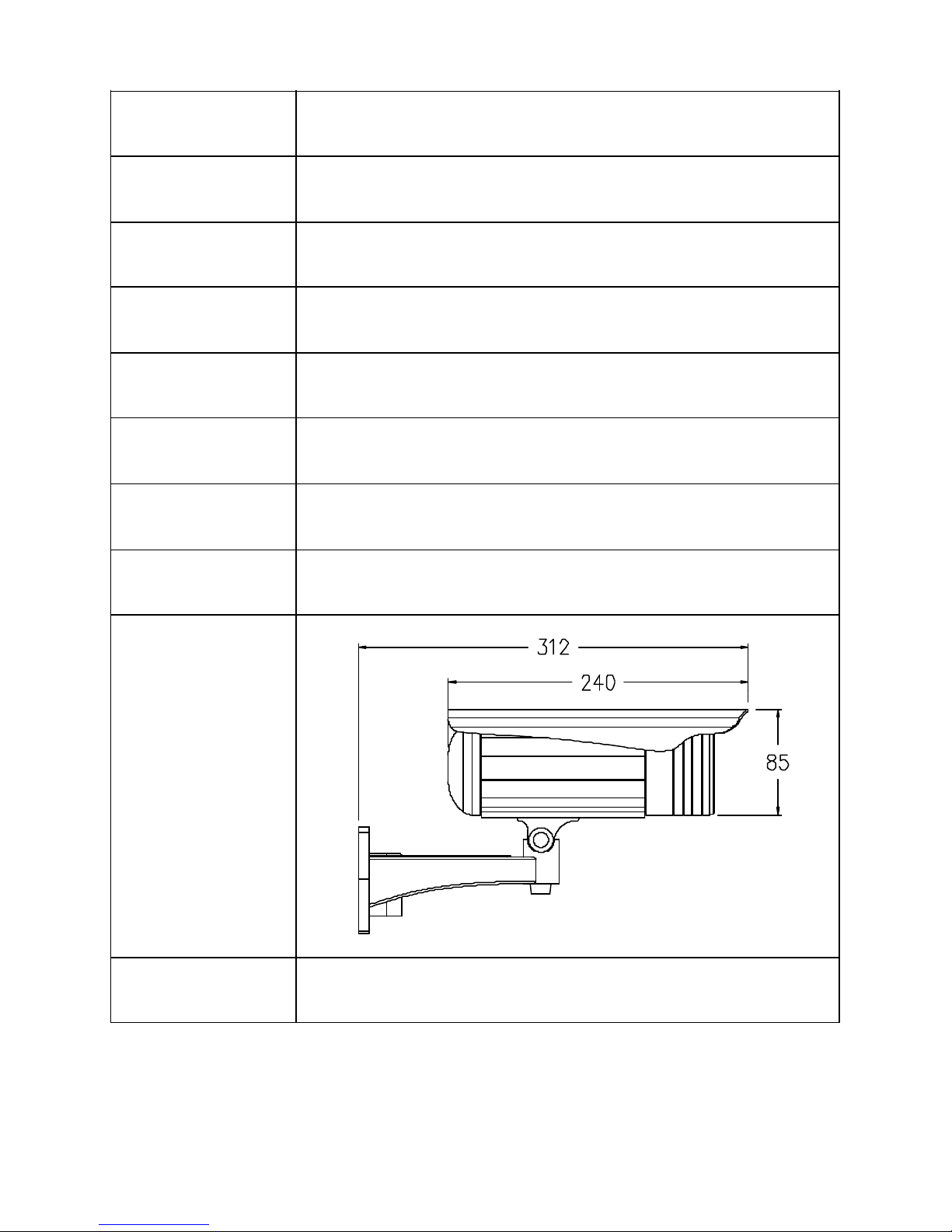
Dimensions(
mm)
CMS Client
and SDK
Open API for application integration including
SDK
Table of contents
Other Dipol Security Camera manuals


