Direct Healthcare Dyna-Form Mercury Advance User manual

DIRECTHEALTHCARESERVICES.CO.UK
Service Manual

DIRECTHEALTHCARESERVICES.CO.UK
2
DYNA-FORM MERCURY ADVANCE
The Dyna-Form Mercury Advance is a pressure relieving mattress for patients at
“High / Very High Risk” of pressure ulcer damage.
Offering high levels of patient comfort, this unique system has the facility to “step up” to that of a
dynamic mattress when clinically required. Similarly, the mattress‘s function can be downgraded
as the patient’s condition improves.
These features make it particularly beneficial for use within the patient’s home or palliative care
environment and help reduce logistic and decontamination costs. The clinical benefits of a single
system are equally applicable to those of a modern hospital setting. A higher maximum weight
capacity, up to *40 stone / 254kg, allows the product to meet the modern challenges of those
heavier clients. All component parts are interchangeable and replaceable, maximising product
life and reducing environmental impact.
*Denotes when in Static Mode
Contents
1. Introduction ..........................................................................................................................3
2. Quick Reference Guide & Frequently Used Functions.................................................................3
3. Troubleshooting ....................................................................................................................4
4. Installation ........................................................................................................................... 5
5. Operation ............................................................................................................................. 6
6. Transportation ....................................................................................................................... 6
7. Audible Warnings ................................................................................................................... 7
8. Maintenance Procedures ....................................................................................................... 7
9. Technical Data ..................................................................................................................... 13
10. Optimum Conditions for Transport, Storage and Use .............................................................. 13
11. Symbols Guide & Contraindications for Use ........................................................................... 14
12. Detachable / Removable Parts ............................................................................................. 15
13. Disposal ............................................................................................................................ 15
3
DIRECTHEALTHCARESERVICES.CO.UK
SERVICE MANUAL
1. Introduction
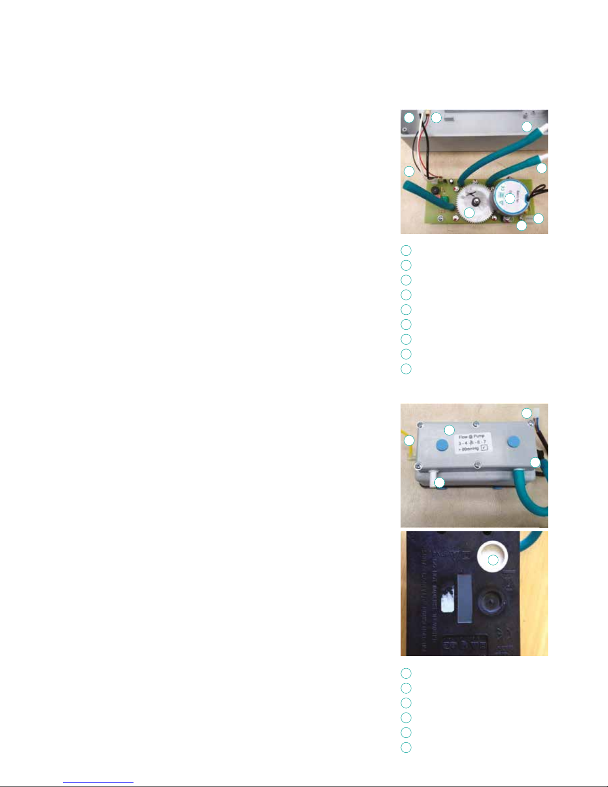
The Mattress consists of a foam head cell and series of 14 transverse air cells, each containing a unique
foam profiled insert, which are in turn held within a foam U Core, all protected by a vapour permeable
waterproof cover. The single head end cell and the formers consist of foam only. The transverse cells
are arranged into alternate pairs of A and B cells which are filled and emptied in sequence.
In Static Mode, the mattress attains the pressure reducing properties of the Dyna-Form Mercury
static foam mattress (details available on request), whilst in Alternating Mode the mattresses is
able to offer similar properties to a pressure relieving dynamic system.
The Mattress consists of a series of 14 transverse air cells, each containing a unique foam
profiled insert, which are in turn held within a foam U Core, all protected by a vapour permeable
waterproof cover. The transverse cells are arranged into alternate pairs of A and B cells which are
filled and emptied in sequence while the single head end cell and the formers remain inflated.
The digitally controlled Power Unit controls a pump that allows air to flow into, or out of the air
cells as required according to the operating mode selected. It also maintains the air pressure
within the mattress at the required level and controls the action of the audible/visual Audible
Warning system in the event of mains supply failure or over or under inflation pressure. A CPR
Valve located at the pump end of the umbilical hose permits the rapid deflation of the Mattress in
an emergency.
Power Switch Audible Warning Reset
The power switch simply switches the mains power to the pump on and off.
When the pump detects an Audible Warning condition, this can be silenced as below and re-
set by switching the pump off and then back on again.
CPR Valve
Please ensure that the CPR connector is always placed fully home, prior to inflating the
mattress. NB: The mattress will NOT inflate properly should this not be the case.
The CPR connector is only to be used in the event of a clinical emergency for priority use.
However, disconnecting this function will cleverly deflate air rapidly from the mattress in
readiness for transport / static mode.
2. Quick Reference Guide (Frequently used functions)
This is a quick reference guide for the Dyna-Form Mercury Advance System
Product Code MAT/MERADV/198/88/15

DIRECTHEALTHCARESERVICES.CO.UK
4
DYNA-FORM MERCURY ADVANCE
Symptoms Problems / Cause
Low Pressure The mattress is set to a mode that
is too SOFT.
Change the mode button to standard (from Lo to High(+)
a firmer pressure setting) as required. If the mattress is still
too soft after a short period of 5 to 10 minutes, then please
call an engineer.
The CPR connector is not fully home. Check all tubing is not kinked within the mattress.
There may be a leak in the system. Ensure that the tubing within the mattress is fully connected.
High Pressure The mattress is excessively firm on a
constant basis.
Set mattress to a softer setting as clinically required.
Evaluate that the mattress to be of a “less firm” state after
a short period of 5 to 10 minutes.
If this is not achieved, then please follow the task as below
before calling an engineer for assistance.
Note: Check all tubing is not kinked within the mattress.
Points to check
3. Troubleshooting
This symbol when illuminated (The blue indicator light) is not used to indicate that the
equipment is on or ready for use.
When a patient requires a true dynamic function or indeed more pressure in the cells,
as they may be uncomfortable or feel as though the support surface if too soft or unstable,
then please select a “Hi” setting (pressure 26mmHg). This must only be used by a trained
clinician as often too higher pressures can further agitate certain patients conditions.
When a patient requires less pressure in the cells, as they may be uncomfortable
or indeed hyper sensitive to cell movement or indeed if the patient is still reddening further,
then please select a “Lo” setting. This must only be used by a trained clinician.
This function is used to silence the Audible Warning. The LED will remain lit if the Audible
Warning has been silenced previously, however a fault is still detected. Refer to the power
switch (as above) in order to re-set fully. If the Audible Warning continues to sound repeatedly,
along with an illuminated light, then an engineer must be called.
This symbol indicates an “Audible Warning Failure”.
Please see trouble shooting guide below for how to re-set.
LED Mode Settings
Power On / Off
True Dynamic /Firmer Setting
Lo I Comfort Pressure Setting
Silence Audible Warning
Audible Warning Failure
Note: Please ensure that all securing straps on the base of the mattress are secured onto the
NON MOVING PARTS of the bed frame.
For shut down procedure, see 4.2 Power Unit (Pump) section.

5
DIRECTHEALTHCARESERVICES.CO.UK
SERVICE MANUAL
4. Installation
4.1. Mattress (This is the applied part type BF)
Place the Dyna-Form® Mercury Advance Mattress directly on to the bed platform ensuring that
the Blue multi-stretch waterproof cover is on top and that the umbilical hose is located at the left
hand corner at the foot end of the bed. Note: The umbilical hose can be located inside the cover
under the “Open Here for Air Inlet” printed in the bottom left hand corner of the mattress.
Cover the Mattress with a loose fitting sheet.
Static Mattress Use
The Dyna-Form® Mercury Advance Mattresses can be used as a pressure reducing mattress for
patients at High / Very High Risk of pressure ulcer damage without the need to attach the pump.
Alternating Mattress Use
If / When required, the Dyna-Form® Mercury Advance Mattress can be used as an alternating
mattresses system by attaching the Dyna-Form® Mercury Advance pump system.
No other
system should be attached to the mattress as the design settings and internal air pressure
properties of the Dyna-Form® Mercury Advance pump are specific to this mattress only.
The Dyna-Form® Mercury Advance is a replacement mattress system and should NOT be placed
on top of any existing mattress.
The startup time from static to dynamic mode is immediate.
4.2. Power Unit (Pump)
Hang the Power Unit (Pump) onto the footboard. The mounting hooks swivel to suit the thickness
of the footboard or rail. Connecting the Umbilical Hose to the Power Unit (Pump), place the 3-pin
electrical plug into the wall outlet and switch on:
(a) Open the zip located at the bottom left hand side of the mattress and pull out the Blue Umbilical
hose.
(b) Attach the Blue Umbilical Hose to the Power Unit (Pump) by connecting the air connector
at the end of the Umbilical Hose to the air inlet connector at the bottom left hand side of the
pump. Ensure that the Red CPR Release button is located on top of the Air Inlet connector
after connection is complete.
(c) Re-close the zip as far as possible without clamping the Blue Umbilical Hose to ensure the
mattress and air cells are sealed within the cover.
(d) Shut down is the reverse of items a, b & c above.

DIRECTHEALTHCARESERVICES.CO.UK
6
DYNA-FORM MERCURY ADVANCE
5. Operation
Attach the mains cable to the pump by inserting the “kettle” type connector into the recess
on located on the left hand side of the pump. The mains cable has been designed specifically
as a removable part to aid in easy replacement should it become damaged in use.
The mains plug should be turned off and removed from wall socket as a means of isolation.
Plug the mains cable into a suitable 230v mains socket and switch on the Power Unit using the on/off switch.
After the pump has been turned on both the “Hi “and the “Lo” lights will flash together intermittently
until the pump has attained its initial operating pressure. Once the pump has attained its initial
operating pressure the “Lo” light will stay on constantly and the mattress is ready for use.
5.1. Lo / Hi Settings
The Dyna-Form® Mercury Advance Mattress, in Alternating Mode, has two pressure settings.
The initial setting that the pump will revert to upon set up is “Lo”. The “Lo” comfort setting is ideal
for the lighter patient of those who feel discomfort when on a normal alternating air type mattresses
system. However, for patients with existing pressure damage or those at Very High Risk, it is
recommended that dependant on the clinical judgement of the clinician, the “Hi” setting is activated
by pressing the +/- button once, which is located on top of the pump.
In “Hi” Mode the pump attains more of the characteristics of an alternating air mattresses system
whilst still utilising the advantages of the static foam inserts. Repeatedly pressing the ‘mode’ button
enables the Lo & Hi modes to be selected in turn.
5.2. CPR Deflation
The CPR system consists of a manually operated button located on the Air Inlet connector attached
to the pump. By pressing the Red Button, which will release the connector locking system, the user
can remove the connector unit which will deflate the mattress air system back to that of a static
foam mattress.
Note: After a short period as the Mattress deflates the ‘Low Pressure’ Audible Warning is activated and can be cancelled
by switching the Power Unit off.
5.3. Troubleshooting
For assistance (if needed) in setting up, using or maintaining the Mercury Advance System, or to
report unexpected operation or events, please contact Direct Healthcare Services on the contact
details on the reverse of this manual.
6. Transportation
To change the location of the mattress, remove the Umbilical cord and allow the mattress to
return to its Static Mattress form. Switch off the Power Unit (Pump) using the on/off switch and
disconnect the electrical supply cable from the mains socket. The mattress can now be moved to
a new location where it must immediately be reconnected to the mains electrical supply and the
Power Unit (Pump) switched back on. Once the Mattress has been refilled, the ‘Alternating’ mode
will automatically revert back to the Lo setting and should be reselected to Hi should this be desired
by the clinician.
Warning: The Mattress will not ‘alternate’ when disconnected from the Power Unit (Pump) and /or the mains electrical.
Also refer to environmental conditions section at rear of this manual.

7
DIRECTHEALTHCARESERVICES.CO.UK
SERVICE MANUAL
8. Maintenance procedures
8.1. Safety Warning
Only qualified technicians trained or formally approved by Direct
Healthcare Services Ltd. in the operation and maintenance of
Direct Healthcare Services products may carry out maintenance,
modification or repair work on the equipment. Unqualified
personnel attempting to work on Direct Healthcare Services
Power Units risk serious injury to themselves and others and
possibly death by electrocution. Inlet fuse NOT to be replaced by
operator or patient, to be replaced by service personnel only.
Warning – Do not modify this equipment without
authorisation of Direct Healthcare Services.
8.1.1 Servicing
Direct Healthcare Services (DHS) recommend that the
Power Unit (Pump) should be serviced every year. The unit
contains no user serviceable parts and should only be carried out
by persons as described in section 8.1. DHS will make available
on request service manuals, component parts lists and other
information necessary for any suitably qualified person (As in 8.1)
to carry out repair or service the system. For Service, maintenance
and any questions regarding this please contact DHS.
8.2. Cleaning Procedures
Warning: Before cleaning the System make sure that the Power
Unit (Pump) is disconnected from the mains electricity supply.
Do not immerse the Power Unit (Pump) in water or other fluids.
Do not autoclave, nor use phenol for cleaning.
Do wash hands before commencing the cleaning process.
Wear appropriate protective clothing such as gloves,
apron and a mask.
Ensure all work surfaces are cleaned before and after contact
with the Mattress.
8.3. Warning – Cleaning the Mattress
1. Cleaning should take place after use or between patients.
2. With cover left on the Mattress disconnect the Mattress from
the Power Unit (Pump).
3. Clean the surface of the wash down table with Hypochlorite
solution or equivalent disinfectant.
4. Wash Mattress top using hot water (60 degrees C) containing
detergent – dry with a paper towel.
5. For heavy contamination use a Hypochlorite solution
1,000 parts per million available chlorine.
6. Using suitable brush, hot water, detergent or Hypochlorite solution,
clean Umbilical Hose and CPR Valve. Dry with paper towel.
7. If required, the Mattress Cover may be removed and
machine-washed at a temperature of 80 degrees C, for not
less than 10 minutes. The individual Air Cells can be wiped
down with established disinfectants.
8. To avoid shrinkage of the cover line dry in an indoor clean
environment or tumble dry on a low heat setting not exceeding
40 degrees C and not for longer than 10 minutes. Covers must
be thoroughly dried before re-fitting to the mattress.
8.4. Warning – Cleaning the Power Unit (Pump)
The Power Unit can be cleaned by wiping with a cloth
dampened with a detergent solution or Hypochlorite solution.
Also refer to symbol chart.
8.4.1 Warning
Ensure the Mercury Advance System is not exposed to:
1. Excessive heat sources e.g. fires, radiators etc
2. Water, particularly emersion of the pump.
7. Audible Warnings
Audible Warning conditions are indicated by a flashing red display accompanied by an audible warning.
In each case the user should respond by turning the Power Unit’s switch off and investigating the cause.
7.1. High Pressure Audible Warning
This condition could be caused, for example by a kinked Umbilical Hose or visitors, and others,
sitting suddenly on the Mattress.
7.2. Low Pressure Audible Warning
This condition could be caused, for example, by incorrect fitting of the air inlet connector,
opening of the CPR Valve or a leak in the Mattress due to a cut or puncture.
7.3. Mains Failure Audible Warning
If mains power is lost the all Mode lights will turn off. This Audible Warning condition will only be audible.
The red Audible Warning light will not flash.

DIRECTHEALTHCARESERVICES.CO.UK
8
DYNA-FORM MERCURY ADVANCE
8.5 Serial Number Identification.
The serial number is made up of a combination of 3 data sets. The first four digits
are the serial identifier. The fifth and sixth digits are the week of manufacture and the
seventh and eighth digits represent year of manufacture.
The above pump serial number is 77785113.
This shows that pump number 7778 was made during the week 51 year 2013.
8.6 Opening the Pump Unit
To remove the back lid from the enclosure, first unscrew the four corner screws
(Marked A). These are No6 x 30mm Large Flange Pozi BZP self tappers.
8.7 System Layout
8.8 Checking the System
1. Plug in a mattress system to the Air Outlet.
2. Plug in the mains cable to the IEC inlet and switch on the power.
3. The three LED lights will flash on the control panel.
The red LED shows that the system has low pressure.
4. The compressor will start running and inflating the mattress.
5. Once the system reaches 18mmHg just the LO LED will be lit.
6. The compressor will switch on and off to regulate the mattress pressure.
7. The system is ready for use.
A A
A A
DC Power Inlet 5v
Control PCB
Compressor Air Silencer
AC Power Inlet 240v
Pressure Transducer Outlet
Compressor Power Outlet
Compressor Air Outlet
Air Outlets
Rotor PCB
IEC Power Inlet
Motor / Gearbox Assembly
1
2
3
4
5
6
7
8
9
10
11
1 2
4
3
5
6
7
8
10
11
9
9
DIRECTHEALTHCARESERVICES.CO.UK
SERVICE MANUAL
8.9 Taking the System Apart
1 Remove the four lid screws and lift off the lid.
2 Slide the IEC inlet up and out of the case and unplug the 4way connector
from the Rotor PCB.
3 Unplug the compressor power cable from the Control PCB
4 Remove the yellow capillary tube from the pressure transducer
and green hose from the air silencer.
5 Lift the compressor out of the case.
6 To remove the Rotor PCB first unplug the AC and DC power inlet wires.
7 Now disconnect the green air outlet tubes from the grey air outlet connectors
by pulling them apart.
8 Unscrew the x3 mounting screws with a pozi screw driver.
9 Lift the Rotor PCB out of the case.
To remove the Control PCB:
10 First slide off the PCB mounting fingers from either end of the Control PCB.
11 Now tip the Control PCB back into the case. Make sure that the brown switches
are not catching before you lift the PCB clear of the case.
12 The case is now empty of all assemblies.
8.9.1 Detailed Breakdown & Workings of the Rotor & Rotor PCB
1. Ensure that the Air Distributor Rotor is slowly and smoothly turning, without
jerking. It does not matter if it is turning clockwise or anti-clockwise.
2. Now disconnect the mattress hose and connect a flow meter to the grey air outlet.
During the 12 minute cycle you should be able to measure a flow of 3-4 litres /
minute from each port.
3. Finally pull the power cord out of the IEC socket. The mains failure Audible
Warning should sound. This is a continuous solid tone.
8.9.2 AC Inlet & DC Power Supply
240v AC Supply
5v DC Supply
Air Outlet Tube A
Air Inlet Tube
Air Outlet tube B
Mains Failure Switch Input
Air Distribution Rotor
Sync Motor / Gearbox
240v AC Power Inlet
1
2
3
4
5
6
7
8
9
1 2
3
4 5
6 7 8
9
12
11
10
9
10
8
7
2
5 6
3

DIRECTHEALTHCARESERVICES.CO.UK
10
DYNA-FORM MERCURY ADVANCE
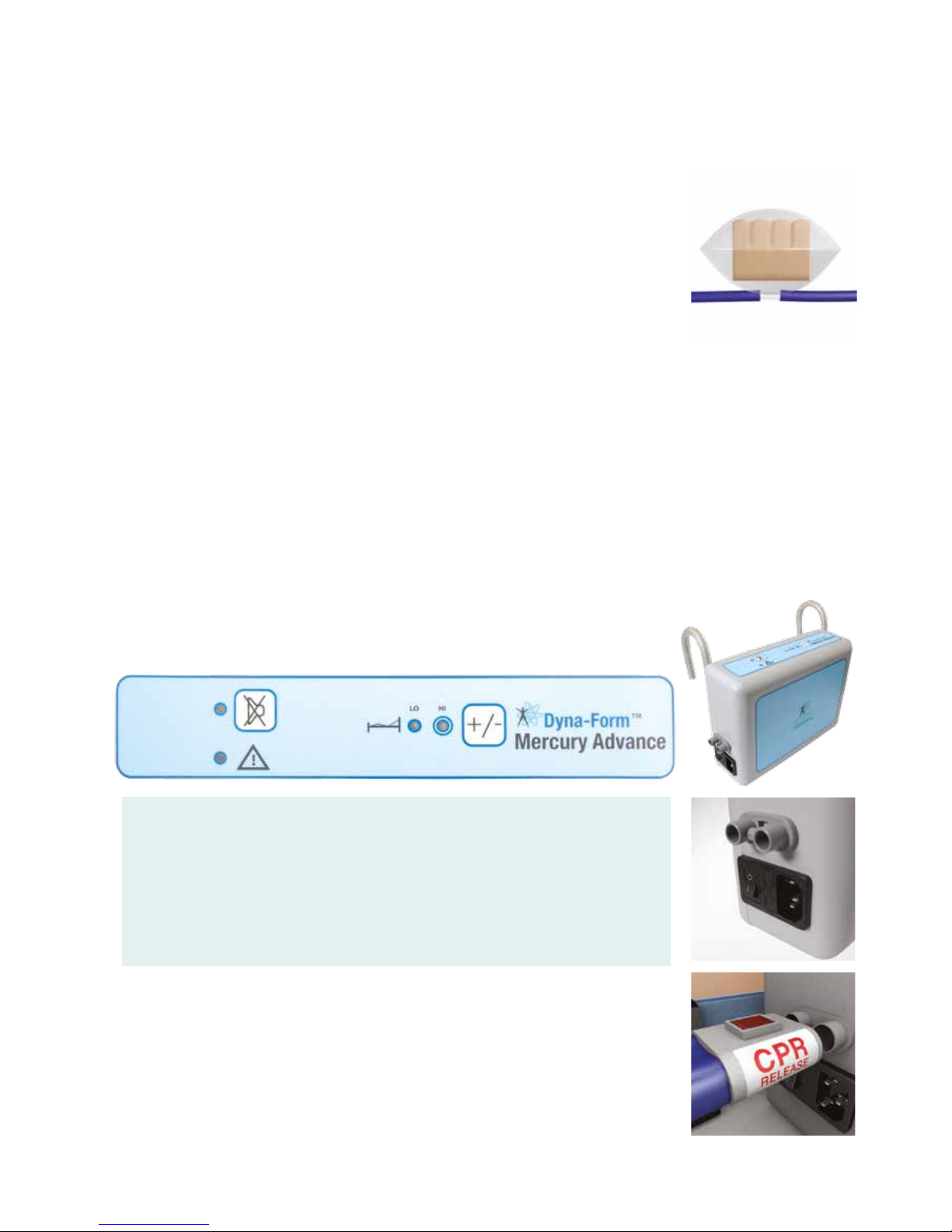
4. Unscrew the two 4BA nuts which hold the motor / gearbox into position.
Then disconnect the motor wires from the PCB connector.
5. Lift the motor off the mounting screws.
6. When 240v AC is applied to the inlet connector you should be able to get a reading
of
240v AC on both sides of the green 5 Amp fuses. If not then the fuses have
blown.
7. This would mean fitting a new Rotor PCB.
8. Before fitting a new Rotor PCB the reason why they have blown should be found,
as they are a safety net. The 500 mA / 1 Amp fuse in the IEC socket should always
blow and protect these internal fuses.
9. The DC power supply is very simple and only produces about 30-50 mA at 5v DC.
10. The 240v AC is firstly fed through the two large yellow dropper capacitors.
11. Then the output from them is fed into in the bridge rectifier which produces a raw
DC supply of about 30vDC.
12. This output is then clamped to 12v DC by the zener diode and smoothed by a
capacitor before being fed into a 5V voltage regulator.
13. The 5V DC power is then fed onto the Control PCB and the Mains Failure
Audible Warning Circuit.
Mains Failure Circuit
DC Power Supply Circuit
Zener Diode
Dropper Capacitors
240v AC Motor Outlet
Bridge Recifier
5 Amp Fuses
240v AC Power Inlet
Mains Failure Switch Input
1
2
3
4
5
6
7
8
9
240v AC Outlet
5v DC Outlet
5v Regulator
Smoother Capacitor
Mains Failure Buzzer
Battery Charging Diode
Mains Failure Relay
Mains Failure
Rechargable Battery
1
2
3
4
5
6
7
8
1 2 3 4
5 6
7 8
5
6
7
8 9
1
2
3
4
4
14. The photo (right) shows the position of the smoother capacitor and voltage regulator.
15. The output from the regulator is fed to the 5vDC outlet connector and also to the mains
failure circuit.
16. As soon as mains power switch is switched on, the other pole of the IEC switch
completes the circuit for the buzzer, powered by the small green rechargable battery.
17. If mains power is connected then the DC power supply generates a voltage which
switches on the relay. This breaks the buzzer circuit.
18. If the mains power is disconnected then the DC supply drops out and the relay
switches off. this activates the buzzer.
19. The rechargable battery is trickle charged through the charging diode.
20. If the battery is totally flat then it will take about 1 minute before the battery is
sufficiently charged to activate the buzzer

11
DIRECTHEALTHCARESERVICES.CO.UK
SERVICE MANUAL
8.9.3 Removal of Air Distribution Rotor and Gasket
1. The photo (right)
shows the Rotor PCB with the Air Distributor Rotor removed.
2.
Firstly using a pozi driver and an M4 spanner unscrew the nyloc nut.
3. Then push the screw down through the PCB and remove the spring and
spring holders.
4. Finally pull the rotor gear off the screw.
5. Check that the venting hole is clear of any debris, so that the system can
properly vent.
6. Next check that the Rotor Air Seal is in good condition.
7. Ensure that the blue PPT foam is not delaminated from either the plastic gear or
that the PTFE glass cloth has not delaminated from the Blue PPT foam.
8. Check that all the teeth on the gear are not damaged and that none are missing.
9. When replacing the rotor either use a new nyloc nut or put some thread lock onto
the thread to ensure it does not vibrate loose.
10. Do not over tighten the nut. The rotor should be able to turn easily by hand.
11. The above photo shows the Rotor PCB with the Air Distributor Rotor removed.
12. The Air Inlet tube is connected to the Rotor Air Feeds by air channels made by the
gasket under the PCB.
13. The Rotor Air Feeds supply the pressurized air into the Rotor Air Seal and this
distributes the air to either the Rotor Outlet A or B.
14. The rotor takes 12 minutes to make a complete cycle.
15.
During the cycle the rotor will feed Outlet A for 5 mins then Outlets A + B for about
1 min fol- lowed by Outlet B for 5 mins and finally Outlets A + B for the last 1 minute.
16. When both A + B are connected this is known as the ‘crossover’ phase.
17. To remove the gasket plate, use a pozi driver and an M5 spanner to unscrew the
5 fixing screws. Once all five nuts are off pull the two PCBs apart.
18. The rubber gasket is held in position by mounting lugs on the gasket.
19. When refitting the gasket plate ensure that it is not over tightened.
20. Finally use thread lock to prevent screws from coming undone by vibration.
M4 Nyloc Nut
M4 x 50mm
Compression Spring and Holders
Venting Hole
Rotor Air Seal
Rotor Gear
1
2
3
4
5
6
1
2
3 4
5
6
1 2
3 5 4
6
7
8
Air Outlet A
Air Outlet B
Mounting Screw Hole
Rotor Outlet A
Rotor Outlet B
Air Inlet
Rotor Air Feeds
x5 M5 Gasket Fixing Screws
Rubber Gasket
1
2
3
4
5
6
7
8
9
9
DIRECTHEALTHCARESERVICES.CO.UK
12
DYNA-FORM MERCURY ADVANCE
8.9.4 Testing the Rotor PCB
1. Connect the IEC socket to the inlet connector, using the four way header.
2. With a mains cable connected turn on the power switch. The mains failure buzzer
should sound
3. Plug in a power lead and the buzzer should stop.
4. The Rotor will slowly turn, either clockwise or anti-clockwise. Either is OK.
5. Attach a multimeter to the AC power leads ( black and white wires) The meter
should show 240 v AC.
6. If the readings are dead then check both the PCB fuses and the IEC inlet fuse.
7. Attach a multimeter to the DC power leads ( black and red wires) The meter should
show 5vDC.
8. Connect a pressurized air source ( needs at least 80mmHg) to the air Inlet tube and
then connect the Air outlet tubes to two pressure meters.
9. As the rotor turns the pressure meters should read a minimum of 80mmHg on
each side.
10. If one meter is reading considerably different to the other then check the gasket
screws are tight enough and that the tubes do not have any perforations.
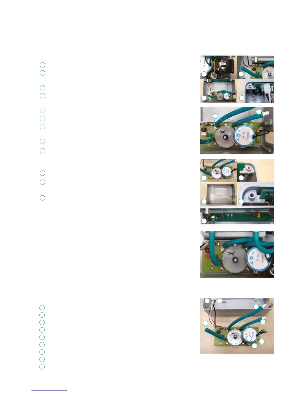
8.9.5 Testing the Compressor
1. Connect the compressor to a mains power supply.
2. Connect the Air outlet to a flow meter and the capil- lary tube to a pressure meter.
3. The Air flow should be a minimum of 4 lpm
4. the pressure should be at least 80mmHg
5 If the air flow or pressure is low then check air silencer is screwed down and that
tubes do not have any perforations.
6. If no other faults can be found then replace the pump valve body and rubber
diaphragms.
7. If the air filter felt is grey and dirty then replace with a new item.
240v AC Supply
5v DC Supply
Air Outlet Tube A
Air Inlet Tube
Air Outlet tube B
Mains Failure Switch Input
Air Distribution Rotor
Sync Motor / Gearbox
240v AC Power Inlet
1
2
3
4
5
6
7
8
9
1 2
3
5
4
6
9
8
7
1
2
3
5
6
4
Pressure transducer connection
Air silencer block
240v 50Hz Input
Smoothed Air outlet
Compressor Outlet
Air Inlet Filter
1
2
3
4
5
6

13
DIRECTHEALTHCARESERVICES.CO.UK
SERVICE MANUAL
8.9.6 Testing the Control PCB
1. Connect a 5v DC supply to the DC inlet.
2. Connect 240v supply to AC inlet. and compressor to Pump Outlet.
3. LEDs will light up and flash whilst buzzer beeps and compressor will run
4. Connect pressure tube to lower port of the pressure transducer. Once pressure hits
18mmHg then the pump will stop and only the Lo LED will show.
5. Release the pressure and the pump will restart.
6. If the pressure is below 10mmHg then the pressure mode can not be changed.
7. Apply pressure to transducer. Press the Pressure switch and the Hi LED should light up.
8. When pressure reaches 28mmHg then pump will stop.
9. Apply pressure of over 80mmHg to transducer and the High pressure Audible Warning
should sound. This is a fast beeping with the red Pressure Audible Warning LED flashing.
11. Release all pressure and after 90 secs the low pressure Audible Warning will
be activated. This is a slow beep with the red flashing LED.
A list of spares and part numbers are available on request from
Direct Healthcare Services
8
10 9
Mute LED
Mute Switch
Pressure Audible Warning LED
Lo LED
Hi LED
Triac (pump switch)
Pressure Switch
Pressure Transducer
5v DC Inlet
240v Inlet
Microprocessor
240v AC Pump Outlet
1
7
2
8
3
9
4
10
5
11
6
12
12
7
3
1 4 2 5 6
11
9. Technical data
9.1. Power Unit (Pump)
Serial Number ............................As per label on rear of pump
Electrical Supply. ...................................220-240 volt, 50 Hz
Power Consumption ...............................................10 watts
Fuses ................................................................TA1H 250V
Protection against shock ...........................................Class 2
Noise Level ...............................................Approx. 30 dB (A)
Dimensions ...........................................235 x 180 x 80 mm
Weight...................................................................... 1.7 kg
Service Interval....................................................12 months
Expected life ............................................................5 years
Shelf life of parts ......................................................5 years
9.2 Mattress
Serial Number .....................Label on inside of mattress cover
Number of Air Cells ................ 14 Air Cells / 1 Static Foam Cell
Dimensions ........................ 880 x 1980 x 150 mm (Nominal)
Weight.....................................................................13.4kg
Expected life of Mattress ...........................................5 years
Shelf life of Mattress parts .........................................5 years
10. Optimum conditions
(Applies to Mattress and Pump)
10.1 Environment conditions for transport,
storage and use
Transport .................................................... -5˚C – +40˚C
Storage ........................................................5˚C – +40˚C
Usage ........................................................15˚C – +40˚C
Humidity .......................................................... 10% – 93%
Atmospheric Pressure ........................... 700hPa – 1060hPa
Operational Altitude .............................................. ≤ 2000m
10.2 Exposure
Exposure to direct sunlight, dust, lint and general debris is not
considered to be an issue with the Mercury Advance System.

DIRECTHEALTHCARESERVICES.CO.UK
14
DYNA-FORM MERCURY ADVANCE
REFER TO
USER MANUAL
TUMBLE DRY ON LOW
MEDICAL DEVICES
DIRECTIVE 93/42EEC
DO NOT IRON
DO NOT USE
SHARP INSTRUMENTS
WASH AT 80˚
REFER TO
USER MANUAL
DO NOT BLEACH
MAXIMUM USER
WEIGHT LIMIT
254 KG / 40 ST
ONES
KEEP DRY
DOUBLE INSULATED
CLASS II
NO SMOKING
DO NOT USE
PHENOL
DO NOT DRY CLEAN
TYPE BF
APPLIED PART
MEDICAL DEVICES
DIRECTIVE 93/42EEC
DO NOT DISPOSE OF
WITH HOUSEHOLD WASTE.
PLEASE REFER TO DHS WEBSITE
THIS IS A STATEMENT THAT
ALERTS THE USER TO THE
POSSIBILITY OF SERIOUS INJURY
OR OTHERWISE ADVERSE
REACTIONS WITH THE USE
OR MISUSE OF THE DEVICE
WARNING
THIS IS A STATEMENT THAT
ALERTS THE USER TO THE
POSSIBILITY OF A PROBLEM
WITH THE SYSTEM ASSOCIATED
WITH ITS USE OR MISUSE
CAUTION
CAUTION
HUMIDITY
LIMITATION
ATMOSPHERIC PRESSURE
LIMITATION
PROTECT FROM HEAT
AND RADIOACTIVE SOURCES
TEMPERATURE
LIMITATION
Mattress Symbols
11. Symbols Guide
Contraindications For Use (Warning)
The Mercury Advance System should not be used for patients with
unstable fractures, gross oedema, burns, or intolerance to motion.
General Information (Caution) (Warning)
• Select correct setting ‘Hi’ or ‘Low’ as required. Care should
be taken not to accidently change settings once set. This may
affect the desired requirement of the therapy. This could also
be caused by pets, pests or children.
• There are no special skills required to operate the system.
• The Medical Professional is responsible for applying his/her best
medical judgment when using the system.
• The electricity supply is of the type indicated on the Power Unit
(pump)
• Check the mains lead is free from damage and is positioned so
as not to cause an obstruction, or injury. E.g. Strangulation of a
child or trip hazard.
• Ensure the mains lead cannot become trapped or crushed, e.g. by
raising or lowering of the bed or bed rails or any other moving object.
• The power unit (pump) must only be used with a suitably
approved power cord and plug set as supplied by DHS.
• The system is not to be used in the presence of flammable
anaesthetics.
• Suitable for continuous use.
• Not suitable for sterilisation.
• Do not position the power unit to make it difficult to disconnect
the power supply or plug.
• Do not place the System on or close to a source of heat.
• Do not use with hot water bottles or electric blankets.
• DHS strongly advise against smoking whilst the Power Unit
(pump) is in use. This is to prevent accidental secondary ignition
of items which may be flammable e.g. bed linen. The materials
used in the manufacture of the Mercury Advance System comply
with the required fire safety regulations.
• Do not use sharp objects on or near the mattress system as this
will cause damage.
• Do not store in damp conditions.
• Do not use in an oxygen enriched environment.
• Not suitable for use in an Outdoor Environment.
• Intended for both Home Healthcare and Professional Healthcare
environments.
• Do not connect to any other medical device or equipment.
• Correct fuse rating MUST be used. Failure to do so could result in
the risk of a fire.
• The System should be cleaned after use or between patients.
Refer to Cleaning section.
• All internal and external hoses must be free of twists, kinks.
The external hose should also be properly connected and
positioned so that the risk of obstruction or injury is eliminated.
• Do not use bleach, phenol s. Chlorine based products which
exceed 1000ppm. Solvents or alcohol based cleaners.
• All the above warnings and cautions together with safety
considerations should be observed at ALL times during its use.
General Symbols
REFER TO
USER MANUAL
DO NOT TUMBLE DRY
MEDICAL DEVICES
DIRECTIVE 93/42EEC
DO NOT IRON
DO NOT USE
SHARP INSTRUMENTS
WASH AT 80˚
REFER TO
USER MANUAL
DO NOT BLEACH
MAXIMUM USER
WEIGHT LIMIT
254 KG / 40 STONES
KEEP DRY
DOUBLE INSULATED
CLASS II
NO SMOKING
DO NOT USE
PHENOL
DO NOT DRY CLEAN
TYPE BF
APPLIED PART
MEDICAL DEVICES
DIRECTIVE 93/42EEC
DO NOT DISPOSE OF
WITH HOUSEHOLD WASTE.
PLEASE REFER TO DHS WEBSITE
THIS IS A STATEMENT THAT
ALERTS THE USER TO THE
POSSIBILITY OF SERIOUS INJURY
OR OTHERWISE ADVERSE
REACTIONS WITH THE USE
OR MISUSE OF THE DEVICE
WARNING
THIS IS A STATEMENT THAT
ALERTS THE USER TO THE
POSSIBILITY OF A PROBLEM
WITH THE SYSTEM ASSOCIATED
WITH ITS USE OR MISUSE
CAUTION
CAUTION
HUMIDITY
LIMITATION
ATMOSPHERIC PRESSURE
LIMITATION
PROTECT FROM HEAT
AND RADIOACTIVE SOURCES
TEMPERATURE
LIMITATION
Pump (Unit) Symbols
REFER TO
USER MANUAL
DO NOT TUMBLE DRY
MEDICAL DEVICES
DIRECTIVE 93/42EEC
DO NOT IRON
DO NOT USE
SHARP INSTRUMENTS
WASH AT 80˚
REFER TO
USER MANUAL
DO NOT BLEACH
MAXIMUM USER
WEIGHT LIMIT
254 KG / 40 STONES
KEEP DRY
DOUBLE INSULA
TED
CLASS II
NO SMOKING
DO NOT USE
PHENOL
DO NOT DRY CLEAN
TYPE BF
APPLIED PART
MEDICAL DEVICES
DIRECTIVE 93/42EEC
DO NOT DISPOSE OF
WITH HOUSEHOLD WASTE.
PLEASE REFER TO
DHS WEBSITE
THIS IS A STATEMENT THAT
ALERTS THE USER TO THE
POSSIBILITY OF SERIOUS INJURY
OR OTHERWISE ADVERSE
REACTIONS WITH THE USE
OR MISUSE OF THE DEVICE
WARNING
THIS IS A STATEMENT THAT
ALERTS THE USER TO THE
POSSIBILITY OF A PROBLEM
WITH THE SYSTEM ASSOCIATED
WITH ITS USE OR MISUSE
CAUTION
CAUTION
HUMIDITY
LIMITATION
ATMOSPHERIC PRESSURE
LIMITATION
PROTECT FROM HEAT
AND RADIOACTIVE SOURCES
TEMPERATURE
LIMITATION

15
DIRECTHEALTHCARESERVICES.CO.UK
SERVICE MANUAL
12. Detachable/Removable Parts
1. Mattress (Detached from the pump by removing the
CPR connector). Part No. MAT/MER/ADV/198/88/15
(or variants of for the size)
2. Electric power cable. (Removed from the pump by pulling
the cable away from the mains inlet on the side of the pump).
Part No. DHS/ADV/MLEAD
N.B. The battery is an integral part of the Rotor PCB and is not
removable or changeable.
Caution
Use of detachable parts not listed is not recommended
by Direct Healthcare Services.
13 Disposal
Please refer to DHS website for recommendations and
responsibilities for disposal within the UK WEEE guidelines.
EMI/EMC Statement and Manufacturer’s Declaration
This equipment has been tested and found to comply with the limits of EN 60601-1-2 2007.
These limits are designed to provide reasonable protection against harmful interference in both a medical and residential
environment. This equipment generates, uses and can radiate radio frequency energy and, if not used in accordance with
manufacturer’s instructions, may cause harmful interference to radio communications. However, there is no guarantee that
interference will not occur in a particular installation. If this equipment does cause harmful interference to radio or television
reception or other equipment, which can be determined by turning the equipment off and on, the user is encouraged to try to
correct the interference by one of the following measures:
®®• Reorient or relocate the receiving antenna.
• ®®Increase the separation between the equipment.
®®• Connect the equipment to an outlet on a circuit different from that to which the receiver or equipment was connected.
The equipment having been tested to operate within the limits of electromagnetic compatibility. (Immunity to interference from
nearby sources radiating radio frequency energy). Sources exceeding these limits may give rise to operation faults. Where
possible the system will sense the interference and if it is of short duration transparently take countermeasures whilst operating
near normally, or failing this will issue a warning and take measures for the continued safely of the user. Further increased levels
of energy may cause the system to stop operating, continuously generate random faults or continuous resets.
Try to ascertain the source of the interference by turning nearby or suspect equipment off, and see if the interference effects
stop. In any such event the user is encouraged to try to correct the interference by one of the following measures:
®®• Have the interfering equipment repaired or replaced.
®®• Reorient or relocate the interfering equipment.
®®• Increase the separation between the equipment and the possible source of the interference.
®®• Connect the equipment to an outlet on a circuit different from that to which the interfering equipment was connected.
Information regarding Electro Magnetic Compatibility (EMC) according to IEC60601-1-2:2007, clause 6.8
With the increased number of electronic devices such as PC’s and mobile telephones, medical devices in use may be
susceptible to electromagnetic interference from other devices.
The EMC (Electro Magnetic Compatibility) standard IEC60601-1-2 defines the levels of immunity to these electromagnetic
interferences. From the other hand, medical devices must not interfere with other devices. IEC60601-1-2 also defines the
maximum levels of emissions for these medical devices.

DIRECTHEALTHCARESERVICES.CO.UK
16
DYNA-FORM MERCURY ADVANCE
Direct Healthcare Services Ltd
Unit 6/10 Withey Court, Western Industrial Estate
Lon-y-Llyn, Caerphilly, CF83 1BF UK
Sales Office +44 (0) 845 459 9831 F +44 (0) 845 459 9832 E info@directhealthcareservices.co.uk
www.directhealthcareservices.co.uk
Although Direct Healthcare Services Ltd will endeavour to provide the exact specification as printed,
we reserve the right to change specification without prior notice. All equipment and information within this brochure,
should be used in conjunction with appropriate clinical judgement and nursing procedures.
All products manufactured to standards:
With over 28 years experience in the provision of clinically proven, value for money solutions,
you can be sure that our combination of innovative technologies, designed in partnership with leading clinical
healthcare establishments, meet the needs of most patient groups, including our increasingly elderly population.
Our specialist teams are dedicated to serving your needs by continually striving to provide excellent customer support
through a personalised one-on-one service. Whether you need a full hospital installation or a single item, you can be sure that
by putting your trust in us – we will ‘Deliver the Promise’.
Issue 2 (January 2014)
Table of contents


