DirectCM DCM1100i User manual

1
D
DC
CM
M1
11
10
00
0i
i
User Manual

2
T
Th
he
e
D
DC
CM
M1
11
10
00
0i
i
Thank you for purchasing the innovative DCM1100i system.
We’ve kept your needs in mind when designing this small, efficient
office system.
Y
Yo
ou
u
m
ma
ay
y
n
no
ot
t
e
ev
ve
en
n
k
kn
no
ow
w
i
it
t’
’s
s
t
th
he
er
re
e.
.
The DCM1100i is designed is specifically to be small and quiet. It
adopts Intel® pBTX motherboard technology to enhance thermal
management, system size and shape, and acoustics. In addition, the
power supply features passive power factor correction (PFC), which
allows the power distribution to operate more efficiently.
T
Th
he
e
d
de
es
sk
kt
to
op
p
d
de
es
si
ig
gn
ne
ed
d
f
fo
or
r
d
de
es
sk
kt
to
op
ps
s
With the carefully place vent location, DCM1100i is can be place
vertically or horizontally on office desktops, allowing you some much-
needed flexibility, In addition, this system can accommodate legacy
CRT monitors if need be.
B
Bu
ui
il
lt
t
f
fo
or
r
s
so
ol
li
id
d
s
se
ec
cu
ur
ri
it
ty
y,
,
e
ea
as
sy
y
m
ma
ai
in
nt
te
en
na
an
nc
ce
e
The DCM1100i puts security first. The system features a Kensington
lock and a pad lock, and it supports chassis intrusion detection to
secure your hardware investment. Furthermore, the latest Intel
technology provides added security for networking and administration
function, and the tool-less chassis allows easy maintenance.
Note:
In order to install your new DCM1100i correctly, please read this user’s
manual prior to unpacking and setting up the system.

3
Copyright
Copyright © DirectCM 2006. All right reserved.
Disclaimer: DIRECTCM is not be liable for technical or
editorial errors or omissions contained herein; nor for
incidental or consequential damages resulting from furnishing
this material, or the performance or use this product.
DIRECTCM Corporation reserves the right to change product
specification without notice. Information in this document
may change without notice.
No part of this document may be copied, reproduced, or
transmitted by any means, for any purpose without prior
written permission from DIRECTCM.
Safety Instructions
♦The system conforms to international safety regulations.
Nevertheless, this is an electronic device and should be used
with care. For protection against injury and the risk of
damage, please read this manual and follow al safety
guidelines.
General Information
♦Read all instructions included in this manual
♦Save all instructions for future use.
♦Adhere to all warnings and instructions noted on the system.
♦Unless this manual provides specific instructions, do not
attempt to repair or service this system yourself. Opening or
removing covers marked “Do Not Remove” could expose you
to dangerous voltage points and other risks. Refer servicing
of these marked components to a qualified technician.
Installation Restrictions
♦Follow all warnings and instructions marked on the product.
♦Clean this system with a damp cloth, unplugging it before you
begin. Do not use liquid or aerosol cleaners.
♦Do not use this system near water.
♦To avoid falls, do not place this system on an unstable
surface.
♦Do not block or cover ventilation openings in the system
♦Do not place system near or over a radiator or heat register

4
♦Do not place system in a built-in enclosure unless proper
ventilation is available.
♦Operate this system from power source indicated on the
marking label. If you are unsure about the power type, contact
your dealer or local power company.
♦Do not allow anything to rest on power cord.
♦Do not place system in a location where people can walk on
the power cord.
♦If using an extension cord with this product, ensure the total
ampere rating of the system does not exceed the extension
cord ampere rating. Also, the total rating of all products
plugged in the wall outlet should not exceed the fuse rating.
♦Do not push objects through cabinet slots as they could touch
dangerous voltage points or damage internal parts. This could
result in fire or electric shock.
♦Do not spill or pour liquid on the product.
♦Use a minimum 26AGW wire for telecommunication line cord.
♦Disconnect all telephone lines and power cords prior to
servicing this system.
♦Refer to qualified service technician under the following
conditions:
♦Damaged or frayed power cord or plug
♦Spilled liquid on the system
♦Rain or water exposure
♦System acts abnormally when operating instructions are
followed.
♦System has been dropped or cabinet is damaged
♦System shows a distinct change in performance
5
E
El
le
ec
ct
tr
ri
ic
ca
al
l
r
re
es
st
tr
ri
ic
ct
ti
io
on
ns
s
Warning: This system must be connected to a grounded (earthed)
outlet. To reduce the risk of electrical shock and damage to
the system or loss of data, do not disable the groundling
type plug.
Power cord set requirements
The power cord set (including the appliance coupler, flexible
cord, and wall plug) meets all requirements for use in the
country where the computer was purchased. Power cord sets
for other countries must meet those countries’ specific
requirements. For more information, contact your dealer,
reseller, or service provider.
FCC Information
This equipment has been tested and found to comply with the
limits for a Class B digital device, pursuant to part 15 of the
FCC Rules. These limits are designed to provide reasonable
protection against harmful interference in a residential
installation. This equipment generates, uses, and can radiate
radio frequency energy, and if not installed and used in
accordance with the instructions, may case harmful
interference to radio communications. However, there is no
guarantee that interference will not occur in a particular
installation. If this equipment does cause harmful interference
to radio or television reception, which can be determined by
turning the equipment off and on, the user is encouraged to try
to correct the interference by one or more of the following
measures:
♦Reorient or relocate the receiving antenna.
♦Increase the separation between the equipment and receiver.
♦Connect the equipment into an outlet on a circuit different
from that to which to receiver is connected.
♦Consult the dealer or an experienced radio/TV technician for
help.

6
Table of Contents
Chapter1 Error! Bookmark not defined.
Unpacking Error! Bookmark not defined.
Checklist: ......................................................... Error! Bookmark not defined.
Chapter2 Error! Bookmark not defined.
System Overview 8
Front Panel ...................................................................................................... 8
Rear Panel....................................................................................................... 9
Chapter3 14
Assembling / Disassembling Error! Bookmark not defined.
Removing the Case Cover............................................................................. 14
Removing of Hard Disk Rack......................................................................... 15
Removing of ODD & Card Reader Frame ..................................................... 16
Removing the VGA Card ............................................................................... 17
Removing the Power Supplier ....................................................................... 18
Installing/Uninstalling the Hard Disk Drive..................................................... 19
Installing/Removing the CPU......................................................................... 20
Installing Foot Stand...................................................................................... 23
Appendix 25
System SpeciDirectCMations 25
Product Features ........................................................................................... 25
Technical SpeciDirectCMations..................................................................... 25

7
C
Ch
ha
ap
pt
te
er
r
O
On
ne
e/
/U
Un
np
pa
ac
ck
ki
in
ng
g
Before unpacking your DCM1100i, provide a steady, level, clean
surface located near a wall outlet. The computer should have
enough space around it to allow airflow, especially near the rear
fan. If the system does not have adequate ventilation, internal
components can overheat and be damaged as a result.
Do not damage or destroy the computer box while unpacking.
Rather, save the box in case you need to ship the system in the
future.
Make sure the following components are included in the box and
check to see that they are in good condition. Contact your dealer
immediately if a component is missing or damaged.
•DCM1100i unit
•AC power cord
•CPU heat sink
•HDD cable
•Assembly guide
•Main board user manual

8
C
Ch
ha
ap
pt
te
er
r
T
Tw
wo
o/
/
S
Sy
ys
st
te
em
m
O
Ov
ve
er
rv
vi
ie
ew
w
Front Panel
The features in the front panel are shown in Figure 2.1, and are described as
following.
Figure 2.1
1. Power switch:
Lets you to turn the DCM1100i System on
and off. When you power on, this LED
embedded in Power switch will light blue. If
the button is held down for one second, the
unit will enter Suspend mode, and if held
down for four seconds, unit power will switch
off.
2. HD LED:
When this LED lights yellow, it indicates that
the hard disk is being accessed at the
moment.
3. Line Out jack (light green):
Connect audio devices such as headphones
or speakers to this jack.
Assembling / Dissmebling
9
4. Microphone jack (pink):
Plug the microphone into this jack for
recording or voice-control functions.
5. USB port x 2
Two USB devices can be connected via
these ports; there are a further four on the
rear of the computer – see below.
6. IEEE1394 Connector
1394 devices can be connected via these
ports.
7. Air Inlet
This inlet allows air inside or outside chassis
to be inhaled and exhaled for better air-flow.
8. ODD device:
Insert DVD-ROM into this drive for enjoying
multimedia data.
9. 8-in-1 Card Reader:
Allows users to access and read a variety of
memory cards directly from front panel.
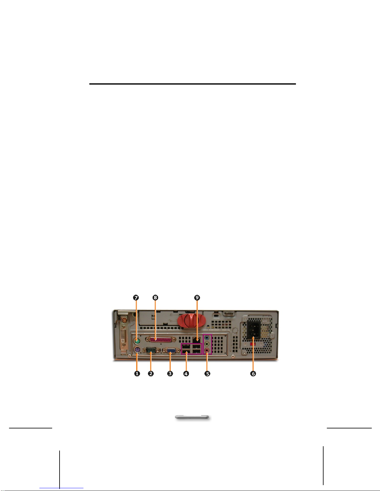
Rear Panel
The features in the rear panel are shown in Figure 2.2, and are described as
following.
Figure 2.2

Assembling / Dissmebling
10
1. PS/2 Mouse connector (purple):
Plug your PS/2 mouse into this connector.
2. COM1 port (turquoise):
Connect serial (RS232) devices such as a modem
to this port.
3. VGA port :
Connect VGA devices such as a display monitor to
this port.
4. USB port x 4
Connect USB peripheral devices to these ports to
take advantage of the universal functionality and
flexibility of Plug and Play technology.
5. HD 2.1 Channel Audio
Line In jack (blue):
Connect audio sources such as tape players to this
jack for recording on your computer or playback
through the Line Out device.
Line Out jack (green)
Connect audio devices such as headphones or
speakers to this jack.
Microphone jack (pink):
Plug the microphone into this jack for recording or
voice-control functions.
6. Power socket:
The power cord is connected to this socket to
ensure the system is connected to a stable AC
power source.
! CAUTION: Before you plug in the AC power cord., check that the
voltage toggle switch is appropriate for your geographic area.
7. Keyboard Connector (green):
Plug your keyboard into this connector.
8. Parallel port (purple):
Parallel devices such as a printer or scanner can be
connected to this port.

Assembling / Dissmebling
11
9. RJ45 LAN connector
For connecting with your LAN to access the network
services or surf the Internet.
Security Mechanism
This system features a specifically designed safety
mechanism to protect the machine.
Figure 2.3
1. Chassis Lock:
A hardware security mechanism, when you place
the switch in lock position, the chassis cover cannot
be opened.
2. Kensington Lock:
A hardware security mechanism, which locks the
chassis to prevent hardware from being stolen.
3. Pad Lock:
A hardware security mechanism, which can lock up
the chassis with lock to prevent being opened.
4. Chassis intrusion:
A hardware security mechanism, once the chassis
cover be opened, the Chassis intrusion will be
touched and will automatically notice the BIOS
system.
Assembling / Dissmebling
12
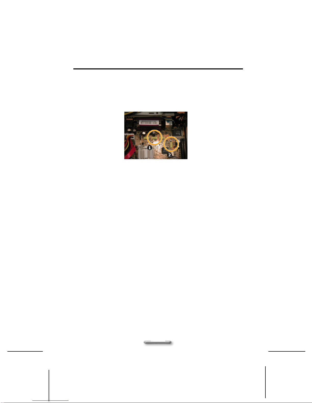
About 1394 and USB connector
For using the peripheral device of IEEE1394 and USB, please
connect the USB and IEEE1394 connectors as shown in shown in
Figure 2.4
Figure 2.4
1. USB Connector:
Connect to USB connector for any USB device.
2. IEEE1394 Connector:
Connect to IEEE1394 connector for IEEE1394
device.
Assembling / Dissmebling
13
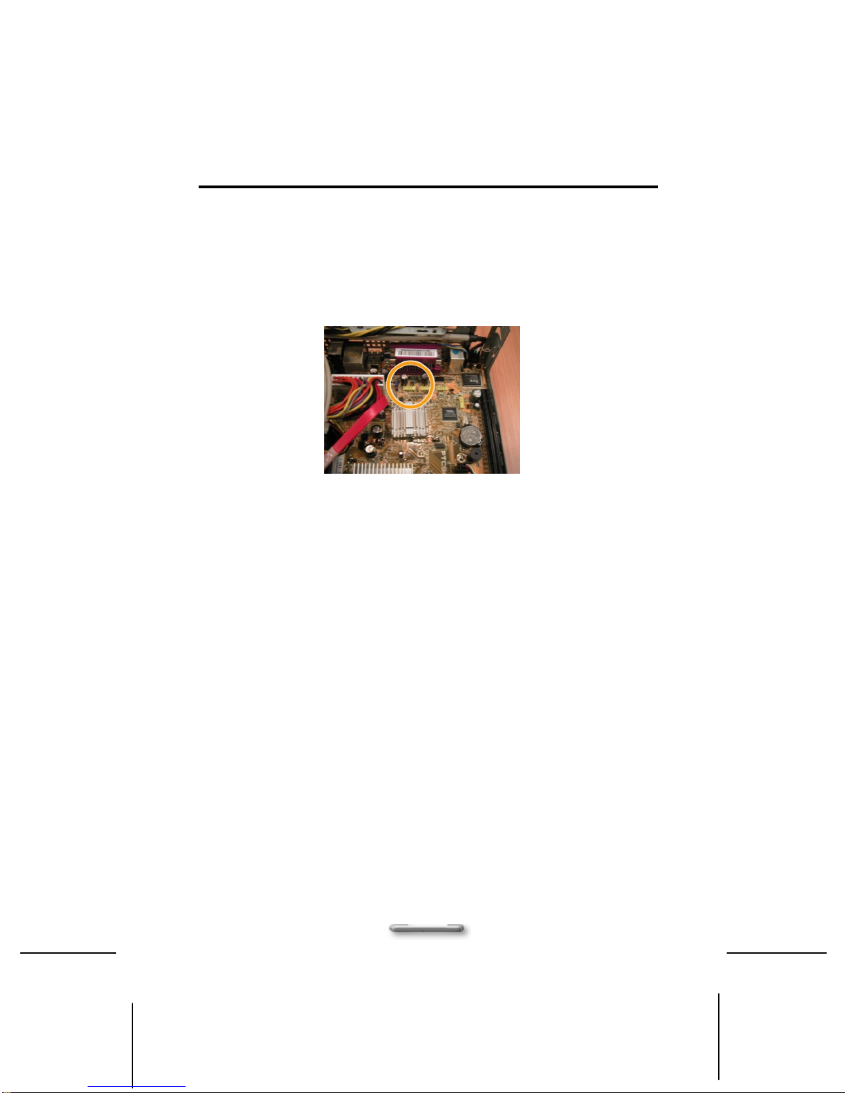
About Card Reader connector
For using card reader, please connect the USB card reader
connector as shown in shown in Figure 2.5
Figure 2.5
Assembling / Dissmebling
14
C
Ch
ha
ap
pt
te
er
r
T
Th
hr
re
ee
e/
/
A
As
ss
se
em
mb
bl
li
in
ng
g
&
&
D
Di
is
sa
as
ss
se
em
mb
bl
li
in
ng
g
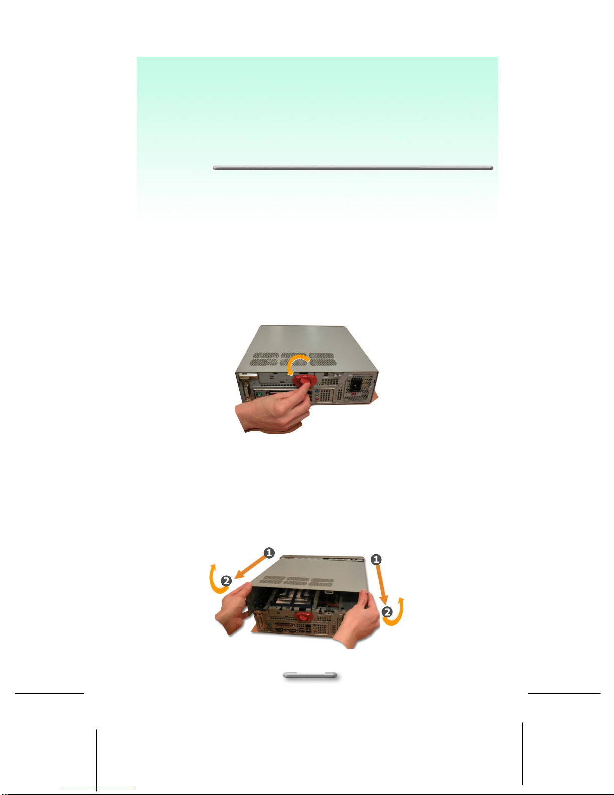
Removing the Case Cover
i. Lay the unit flat, face the rear panel of the unit.
ii. Switch the Chassis Lock to unlock cover position, as
shown in Figure 3.1
Figure 3.1
iii. Pull the cover forward slightly then lift it upwards and
outwards from the back of the unit to remove it as
shown in Figure 3.2.

Assembling / Dissmebling
15
Figure 3.2
Perform the above steps in reverse order to replace the cover.
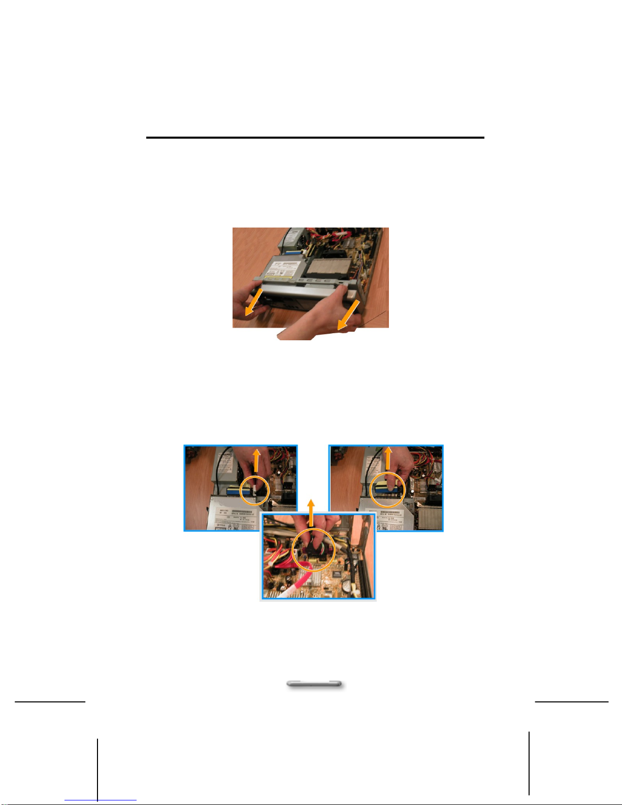
Removing of Hard Disk Rack
i. Before removing the whole hard disk rack from
the main body, please disconnect the flat cable
and power cord of the hard disk, as shown in
Figure 4.1, and Figure
4
.
2
.
ii. S
w
i
tch the Chassis Lock to HDD unlock position, as
shown in Figure 4.3. and remove the hard disk
rack by simply disengage metal tab that
connects to main frame,
Figure 4.3
Figure 4.1
Figure 4.2
Assembling / Dissmebling
16
Removing of ODD & Card Reader Frame
i. Remove the front cover with disengaging metal
tab that hook on bottom and move it forward to
open it.
Figure 5.1
ii. Before removing ODD & Card Reader frame
from the main body, you must first disconnect
the card reader connector, IDE connector and
power connector, as shown in Figure 5.2
Figure 5.2
Card
Reader
Connecto
IDE
Connector
Power
Connector

Assembling / Dissmebling
17
iii. Hold up the shield plate (as indicated by below
drawing circle) and pull forward, you may totally
opened the ODD & card reader rack, as shown
in Figure 5.3.
Figure 5.3
Removing the VGA Card
i. Lift up the VGA board shield plate from the main
braket, as shown in Figure 6.1.
Figure 6.1

Assembling / Dissmebling
18
ii. Disengage metal tab that stepped with main
bracket as indicated in step1, and slightly move
the VGA board to right side as indicted in step 2
to unhook the board from staple.
Figure 6.2
Perform the above steps in reverse order to install the VGA card.
Removing the Power Supplier
i. Pull up the switch to unlock the power supplier,
as shown in Figure 7.1.

Assembling / Dissmebling
19
Figure 7.1
ii. Disengaged the power supplier from the main
frame, as shown in Figure 7.2.
Figure 7.2
Installing/Uninstalling the Hard Disk Drive
i. Hook your hands inward onto the plastic holder
(as indicated in below drawing step 1) and then
lift it upward from the hard disk rack (as
indicated in below drawing step 2), as shown in
Figure 8.1.
Figure 8.1

Assembling / Dissmebling
20
ii. Pull the plastic holder outward a bit for removing
the hard disk, as shown in Figure 8.2.
Figure 8.2
iii. Fix the hard disk rack in position by simply
placing it back to main frame, as shown in
Figure 8.3.
Figure 8.3
Installing/Removing the CPU
i. Remove the CPU heat sink before removing the
CPU. To remove the CPU heat sink from the
main body, you must first disconnect the Power
connector, CPU front fan and rear fan
connectors, as shown in Figure 9.1.
Table of contents


