Sperry Rand Remington Rand UNIVAC 7900 User manual

TYPE
7900·
CENTJl'A;L:
R:ROCES·SO'll
·90
.THE:O·liY
Q;f,
ClPERA.Tl"ON
s·e:rv·lc.e
.M.a·-n.v:.a:J
N;;o.
1

UNIVAC''
Copy
No.
Solid-State
COMPUTER
TYPE
7900
CENTRAL PROCESSOR
90
THEORY OF
OPERATION
Service
Manual
No. 1
"COMPANY
CONFIDENTIAL
REGISTERED
CIRCULATION
The
information
contained
in
this
manual
is
the
property
of
the
Sperry
Rand
Corporation
and
is
Company
Confidential.
It
is
submitted
in
confidence
and
should
not
be
disclosed
to
others
unless
so
disclosed
in
confidence
with
the
permission
of
Remington
Rand
Univac,
Division
of
Sperry
Rand
Corporation,
being
first
obtained.
This
copy
is
numbered
and
is
so
re
gis-
t
ere
d
in
your
name
in
our
records.
The
document
is
not
to
be
reproduced
or
duplicated
without
express
permission
in
writing
from
a
duly
authorized
representative
of
the
Sperry
Rand
Corporation.
This
manual
is
subject
to
recall.
11
~IDft.
"R.u.L
~
Dl\llSION
Of
SPEIRY
IAND
COIPOIATION

TABLE
OF
CONTENTS
Section
Tit
14
I
INTRODUCTION
1-1
1-2
1-3
1-4
1-5
1-6
1-7
1-8
1-9
t-10
1-11
1-12
1-13
1-14
1-15
Functional
Description
Processor
Control
Unit
Storage
Unit
Arithmetic
Unit
Card
Reader
Read-Punch
Unit
Printer
Computer
Language
Computer
Words
Data
Word
Instruction
Words
System
Codes
UCT
Code
Remington
Rand
Card
and
Code
II
LOGICAL
CIRCUITRY
2-1
2-2
2-3
2-4
2-5
2~6
2~7
2-8
2-9
2-10
2-11
2-12
2-13
2-14
2-15
2-16
2-17
2-18
2-19
2-20
2-21
2-22
2-23
Introduc;tion
General
Signal
Polarity
Diode
Circuits
Gates
Buffers
Differences
Connecting
Diode
Magnetic
Amplifiers
Electronic
Differences
Logical
Difference
Decoding
and
Encoding
Matrixes
Decoding
Matrix
Encoding
Matrix
Computer
Timing
-
Pulse
Time
Word
Time
Timing
Signals
Relation
Between
Timing
Signals
and
Word
Time
Signal
Notation
Function
Sig'!als
Control
Signals
Informati()~.
Signals
1-1
1-2
l""'.c3-
_t--~
J~a,
.l-4
1-4
l7'4
1-4
1-5
1:..:s,~
l-6-
I~6
L-~t
l-8
2.:.1.
i;'i
2-1
~2=-2
"i:.:-2
~:;.1
2-3.
2-3
2-3
2-3
2-4
2-4
2-4
2-5
2-6
2-6
2-6
2-7
2-8
2-8
2-8
2-9
2-9

Section
2-24
2-25
2-26
2-27
2-28
2-29
2-30
2-31
2-32
2-33
2-34
2-35
2-36
2-37
2-38
.
2-39
-
2-40
2-41
2-42
2-43
2-44
Title
Logical
Functions
Making a
Gate
Permissive
Alerting
a
Gate
Blocking
a
Gate
Basic
Logical
Circuits
The
Basic
Flip-Flop
Setting
the
Flip-Flop
Restoring
the
Flip-Flop
The
Set
and
Restored
States
The Read
Flip-Flop
Counters
Shift
Register
Timing
Reference
Circulating
Registers
Input
Gates
Recirculating
Gates
of
Register
L
Output
Gates
of
Register
L
Information
Gating
Circuit
Special
Circuit
Elements
Arithmetic
Amplifiers
Transistor
Driving
Amplifiers
III
DESCRIPTION
OF
CENTRAL
PROCESSOR
COMPONENTS
ii
3-1
3-2
3-3
3-4
3-5
3-6
3-7
3-8
3-9
3-10
3-11
3-12
3-13
3-14
'~~15
3..:16
3-17
3-18
3-1'1
3-20
3-21
3-22
3-23
3-24
3-25
3-26
3-27
3-28
Introduction
Control
Unit
Static
Register
Static
Register
Flip-Flops
Stepping
Gate
Ending
Pulse
Buffer
Block
Read
Flip-Flops
Run
Flip-~s
Instruction
Decoder
Function
Encoder"
Register
C
~
Operatorls
Control
Panel
Arithmetic
Unit
Register
A
Input
Ga
t·es
Left
Shift
Gates
Right
Shift
Gates.
Quotient
Input
Gates
Multiplier
Sentinel
Gate
LSD
Complementer
Gate
Recirculation
Gates
Zero
Suppress
Gate
Remington
Rand
to
UCT
Translator
Gates
UCT
to
RR
Translator
Gates
Circular
Shift
Gates
Sum
Input
Buffers
Output
Display
Gates
Output
Circuits
Page
2-9
2-10
2-10
2-10
2-11
2-11
2-11
2-12
2-12
2-13
2-13
2-14
2-16
2-16
2-17
2-17
2-19
2-19
2-20
2-20
2-21
3-1
3-1
3-1
3-2
3-2
3-3
3-3
3-4
3-4
3-6
3-6
3-7
3-7
3-8
3-8
3-8
3-8
3-9
3-9
3-9
3-9
3-10
3-10
3-10
3-11
3-11
3-11
3~12

Section
3-29
3-30
3-31
3-32
3-33
3-34
3-35
3-36
3-37
3-38
3-39
3-40
3-41
3-42
3-43
3-44
3-45
3-46
3-47
3-48
3-49
3-50
3-51
3-52
3-53
3-54
3-55
3-56
3-57
3-58
3-59
3-60
3-61
3-62
3-63
3-64
3-65
3-66
3-67
3-68
3-69
3-70
3-71
3-72
3-73
3-74
3-75
3-76
3-77
3-78
3-79
3-80
3-81
3-82
Title
Register
X
Input
Gates
Right
Shift
Gates
Zero
Suppress
Gate
Comma
Suppress
Gates
Recirculation
Gates
Quotient-Complementing
Gates
Division
Sentinel
Gate
Remainder
Input
Gates
UCT
to
RR
Translator
Gates
Check-Bit
Storage
Gate
Check-Bit
Computer
Gates
Circular-Shift
Gates
Output
Display
Gates
Output
Circuits
Register
L
Recirculation
Gates
M
Gates
S
Gates
Output
Display
Gates
Output
Gates
Outputs
S
Buffers
M
Buffers
Comparator
Quinary
Equality
Circuit
Quinary
Carry
Circuit
Force
Decimal-Carry
Gates
Binary
Equality
Gates
Initial
Force
Decimal-Carry
Circuit
Binary-Carry
Circuit
Binary
Adder
Gates
Conditional
Transfer
Flip-Flop
Time
Selection
Flip-Flop
Complementer
Decimal-Carry
Adder
Quinary
Adder
Sign
and
Control
Circuit
Register
A
Sign
Flip-Flop
Register
L
Sign
Flip-Flop
Register
X
Sign
Flip-Flop
Sign
Display
Circuit
Complement
Flip-Flop
Overflow
Flip-Flop
Overflow
Delay
Flip-Flop
Multiplier/Quotient
Counter
MQC
Flip-Flops
Countdown
Circuit
Clear
MQC
Circuit
IER-OR
Flip-Flops
Storage
Unit
Storage
Drum
Buffer
Storage
Areas
Timing
Band
Page
3-12
3-12
3-12
.3-13
3-13
3-13
3-16
3-16
3-16
3-16
3-16
3-17
3-17
3-17
3-17
3-18
3-18
3-18
3-19
3-19
3-19
3-19
3-19
3-20
3-20
3-20
3-21
3-23
3-24
3-25
3-26
3-26
3-26
3-28
3-29
3-30
3-31
3-31
3-32
3-33
3-33
3-33
3-34
3-35
3-36
3-36
3-37
3-38
3-40
3-40
3-41
3-42
3-43
3-45
iii
Section
3-83
3-84
3-85
3-86
3-87
3-88
3-89
3-90
3-91
3-92
3-93
3-94
3-95
3-96
3-97
3-98
3-99
3-100
3-101
Title
Sprocket
Track
Timing
Band
Read
Circuits
Cycling
Unit
Input-Output
Sentinels
Write
Circuit
Write
Pedestal
Generator
Write
Input
Circuits
Check-Bit
Circuit
Write
Flip-Flop
Phase
Modulation
Coder
Read
Circuit
Read
Flip-Flop
Read
Output
Circuit
Memory
Selection
Circuits
Band
Selection
Flip-Flops
Clear
Band
Selection
Circuit
Head
Selection
Flip-Flops
Switch
Selection
Circuits
Memory
Switch
IV
THEORY
OF
OPERATION
iv
4-1
4-2
4-3
4-4
4-5
4-6
4-7
4-8
4-9
4-10
4-11
4-12
4-13
4-14
4-15
4-16
4-17
4-18
4-19
4-20
4-21
4-22
4-23
4-24
4-25
4-26
4-27
4-28
4-29
Introduction
Basic
Operation
Cycle
Search-for-Instruction
Step
Locating
the
Storage
Address
Comparison
and
Head
Selection
Band
Selection
Staticize-Instruction
Step
Storing
the
p7
Digit
Storing
the
Instruction
Word
Staticizing
the
Instruction
Search-for-Operand
Step
Instruction
Code
Characteristics
Locating
the
Operand
Execute-Instruction
Step
Instructions
with
Two
Execution
Steps
Timing
of
the
Basic
Operation
Cycle
Processing
a
Typical
Instruction
Search
for
Operand
Execute
the
H(60)
Instruction
Memory
Write
Operation
Arithmetic
Operations
Addition
and
Subtraction
Add
Instruction
Subtract
Instruction
Sample
Problems
Multiplication
General
Description
Initial
Conditions
Ml
Step
Page
3-46
3-46
3-47
3-48
3-50
3-50
3-50
3-50
3-51
3-51
3-52
3-53
3-53
3-54
3-54
3-56
3-56
3-57
3-57
4-1
4-1
4-2
4-2
4-8
4-13
4-15
4-17
4-17
4-17
4-18
4-18
4-19
4-20
4-20
4-21
4-21
4-27
4-28
4-29
4-30
4-30
4-30
4-37
4-38
4-41
4-43
4-45
4-45

Section
4-30
4-31
4-32
4-33
4-34
4-35
4-36
4-37
4-38
4-39
4-40
4-41
4-42
4-43
4-44
4-45
4-46
4-47
4-48
4-49
4-50
4-51
4-52
Title
M2
Step
Division
General
Description
Initial
Conditions
Dl
Step
D2
Step
D3
Step
Error
Circuits
Memory-Check
Flip-Flop
Timing-Error
Flip-Flop
Cycling-Unit
Error
Flip-Flop
I/O
Abnormal-Condition
Flip-Fl-0p
Manually-Controlled
Operations
One
Line
Print
One
Card
RPU
One
Card
HSR
One
Instruction
Comparison
Stop
Keyboard
Input
Manual
Operation
Depressing
a Key
Releasing
a Key
Signing
and
Releasing
the
Word
V
INSTRUCTIONS
5-1
5-2
5-3
5-4
5-5
5-6
5-7
5-8
5-9
5-10
5-11
5-12
5-13
5-14
5-15
5-16
5-17
5-18
5-19
5-20
5-21
5-22
5-23
5-24
5-25
Introduction
Input-Output
Instructions
Arithmetic
Instructions
Transfer
Instructions
The
60(H),
56(X),
and
50(J)
Instructions
The
25(8),
05(Y),
and
30(L)
Instructions
The
25(8)
Ins~ruction
The 77(K)
Instruction
Translate
Instructions
The
12(G)
Instruction
The 17{R)
Instruction
Miscellaneous
Instructions
The
20(P)
Superimpose
Instruction
The
35(E)
Extract
Instruction
The 32(N)
Shift-Right
Instruction
The
37(V)
Shift-Left
Instruction
The
62(ZS)
Zero
Suppress
Instruction
The 67 (STOP)
Instruction
Comparison
Instructions
The 82CQ)
Instruction
The
87(T)
Instruction
Test
Instructions
The
22(1
11)
Instruction
The
27(1
21)
Instruction
The
42(1
31)
Instruction
Page
4-46
4-48
4-48
4-52
4-54
4-54
4-59
4-61
4-62
4-63
4-64
4-64
4-65
4~66
4-67
4-67
4-67
4-67
4-68
4-68
4-70
4-71
4-72
5-1
5-2
5-2
5-3
5-3
5-3
5-3
5-3
5-3
5-4
5-4
5-5
5-5
5-5
5-6
5-7
5-8
5-9
5-9
5-10
5-11
5-14
5-14
5-15
5-15
v
Section
Title
VI
ELECTRONIC
CIRCUITRY
vi
6-1
6-2
6-3
6-4
6-5
6-6
6-7
6-8
6-9
6-10
6-11
6-12
6-13
6-14
6-15
6-16
6-17
6-18
6-19
6-20
6-21
6-22
6-23
6-24
6-25
6-26
6-27
6-28
6-29
6-30
6-31
6-32
6-33
6-34
6-35
6-36
6-37
6-38
6-39
6-40
6-41
6-42
6-43
6-44
6-45
6-46
6-47
6-48
6-49
6-50
6-51
Introduction
Diodes
Basic
Theory
Germanium
Structure
Conduction
in
Semiconductors
Doped Germanium
N-Type Germanium
P-Type
Germanium
Junction
Diodes
Forward
Bias
Reverse
Bias
Junction
Diode
as
Rectifier
Applications
Transistors
Clock
Basic
Theory
Common-Base
Circuit
NPN
Transistor
Transistor
as
Voltage
Amplifier
PNP
Transistor
Common-Emitter
Circuit
Symbols
Summary
Voltage
Breakdown
in
Junction
Transistors
Transistor
Identification
General
Description
Principles
of
Operation
Fast
AGC
System
General
Description
Principles
of
Operation
Clock
Output
Voltage
Normal
Clock
Output
Voltage
Low
Clock
Output
Voltage
High
Slow
AGC
System
General
Description
Principles
of
Operation
Clock
Output
Voltage
Normal
Clock
Output
Voltage
Low
Clock
Output
Voltage
High
Phase-Control
System
General
Description
Principles
of
Operation
Phase
of
Clock
Output
Advanced
Phase
of
Clock
Output
Retarded
Change
of
Sprocket
Frequency
Voltage
and
Current
Monitors
Magnetic
Amplifiers
General
Description
Basic
Principles
of
Operation
Magnetization
Curves
Coil
Impedance
Variations
Page
6-1
6-1
6-1
6-2
6-2
6-3
6-3
6-4
6-4
6-5
6-6
6-6
6-7
6-6
6-6
6-9
6-9
6-11
6-12
6-13
6-15
6-15
6-16
6-17
6-18
6-18
6-19
6-22
6-22
6-22
6-23
6-23
6-23
6-24
6-24
6-24
6-25
6-25
6-25
6-25
6-25
6-26
6-28
6-29
6-29
6-31
6-33
6-33
6-34
6-34
6-35

Section
6-52
6-53
6-54
6-55
6-56
6-57
6-58
6-59
6-60
6-61
6-62
6-63.
6-64
6-65
6-66
6-67
6-68
6-69
6-70
6-71
6-72
6-73
6-74
6-75
6-76
6-77
6-78
6-79
6-80
6-81
6-82
6-83
6-84
6-85
6-86
6-87
6-88
6-89
6-90
6-91
6-92
6-93
6-94
6-95
6-96
6-97
6-98
Title
Core
Materials
Complementing
Magnetic
Amplifier
Condition
1
Condition
2
Condition
3
Condition
4
Noncomplemen~ing
Magnetic
Amplifier
Condition
l
Condit.ion
2
Condition
3
Condition
4
Power
Requirements
Mutual
Exclusion
Magnetic
Amplifier
Circuit
Variations
Arithmetic
Registers
Transistor
Amplifier
Package
(TAP)
Storage
Unit
General
Description
Write
Circuitry
General
Description
Diode
Cluster
Write-Transformer
Package
(WXPS)
Write-Amplifier
Complementer-Driver
Package
(WACO)
Read
Circuitry
General
Description
Write-Pedestal
Package
(WPPS)
Read-Amplifier
Package
(RAPS)
Read
Flip-Flop
Package
(RFFS)
Probe
and
Clear
Package
(PBC)
Head
Selection
Matrix-Selector
Package
(MSP)
Head-Switch
Driver
Package
(MSIS)
Power
Control
and
Power
Supplies
Power
Turn-On
Procedure
AC
Distribution
Power-Control
Circuits
Drum
Alarm
Circuits
Power
Supply
Head-Spacing
Detector
Stator
Temperature
Detector
Bearing
Temperature
Rise
Detectors
Power
Turn-Off
Procedure
Power
Supplies
General
Description
Voltage-Stabilizing
Transformer
Power-Supply
Interconnections
Voltage
Monitor
Page
6-37
6-38
6-38
6-39
6-39
6-39
6-40
6-41
6-41
6-42
6-42
6-43
6-44
6-44
6-44
6-45
6-46
6-46
6-47
6-47
6-48
6-48
6-49
6-50
6-50
6-50
6-51
6-54
6-55
6-57
6-57
6-58
6-59
6-59
6-60
6-61
6-62
6-62
6-63
6-64
6-64
6-65
6-65
6-65
6-65
6-67
6-67
vii
j
/
Section
6-t}q
6-100
6-101
6-102
viii
Title
Fuses
Fuse
Fault
Circuitry
Fuseboard
Se~vicing
Precautions
Standard
Symbols
APPENDIX
8
SIGNAL
GLOSSARY
APPENDIX
C
INSTRUCTION
LIST
A
GLOSSARY
OF
TERMS
Page
6-68
6-68
6-70
6-70

Figure
1-1
1-2
1-3
2-1
2-2
2-3
2-4
2-5
2-6
2-7
2-8
2-9
2-10
2-11
2-12
2-13
2-14
3-1
3-2
3-3
3-4
3-5
4-1
4-2
4-3
4-4
4-5
4-6
4-7
4-8
4-9
4-10
4-11
4-12
4-13
4-14
4-15
4-16
5-1
5-2
LIST
OF
ILLUSTRATIONS
Title
Typical
Arrangement
of
New
Univac®
System
·
Central
Processor
Units
Remington
Rand
Tabulating
Card
Basic
Logical
Circuit
Elements
Decoding
and
Encoding
Matrixes
A-Phase
and
B-Phase
Power
Pulses
Twenty-four
Time
Intervals
of
a
Word
Time
Relation
Between
Timing
Signals
and
Word
Time
Typical
Gating
Circuit
Setting
a
Typical
Flip-Flop
Restoring
a
Typical
Flip-Flop
Typical
Counter
Circuit
Typical
Shift
Register
Digit
Positions
of
a
Computer
Word
Distribution
of
Bits
in
a
Circulating
Register
Special
Code
Combination
in
Timing-Band
Read
Circuit
Special
Amplifiers
Storage
Drum
Showing
Computer
Characteristics
Word-Storage
Pattern
Timing
Band,
Expanded
View
Phase
Modulation
Coder
Phase
Modulated
Waveshapes
Search
Step
of
Basic
Operation
Cycle
Drum
Quadrants
Drum
Quadrants
under
Fast-Access
Heads
Quarter
Addition
of
HS2
FF
Inputs
Staticize
Step
Timing
of
Basie
Operation
Cycle
Execution
Step
of
H(60)
Instruction
Add
Instruction
Multiplication
Process
Multiply
Instruction
Division
Process
Dl
Step
of
Division
02
Step,
OR
Phase
02
Step,
OR
Phase
D3
Step
Keyboard
Input
Operation
The
25(B)
Transfer
Instruction
{
(m)--->rA)
The
12(G)
Tranalate
Instruction
(Card
Code
to
UCT
Code)
Page
1-14
1-15
1-16
2-22
2-22
2-23
2-23
2-24
2-24
2-25
2-25
2-26
2-26
2-27
2-27
2-28
2-28
3-58
3-59
3-59
3-60
3-60
4-3
4-6
4-9
4-12
4-16
4-25
4-28
4-35
4-42
4-44
4-50
4-53
4-56
4-57
4-60
4-73
5-16
5-16
ix
Figure
x
5-3
5-4
5-5
5-6
5-7
5-8
5-9
5-10
5-11
6-1
6-2
6-3
6-4
6-5
6-6
6-7
6-8
6-9
6-10
6-11
6-12
6-13
6-14
6-15
6-16
6-17
6-18
6-19
6-20
6-21
6-22
6-23
6-24
6-25
6-26
6-27
6-28
6-29
6-30
6-31
6-32
6-33
6-34
6-35
6-36
6-37
6-38
Title
The
17(R)
Translate
Instruction
(UCT
Code
to
Card
Code)
The
20(P)
Superimpose
Instruction
The
35(E)
Extract
Instruction
The
32(N)
Right-Shift
Instruction
The
37(V)
Left-Shift
Instruction
The
62 (ZS 1)
Zero-Suppress
Instruction
The
82(Q)
Equality-Comparison
Instruction
The
87(T)
Comparison
Instructions
Second
Stage
of
22(1
11),
27(1
21),
and
42(I
31)
Test
Instructions
Covalent
Bond
in
a
Pure-Germanium
Crystal
Hole
Creation
and
Movement
N-Type Germanium
P-Type
Germanium
Charges
in
N-Type
and
P-Type
Germanium
Junction
Diode
with
Symbol
Voltage
Gradients
as
Poteatial
Hills
Biasing
Connections
Diode
Characteristic
and
Test
Circuit
Juncti~n
Diode
Used
as
Rectifier
High
and
Low
Information
Pulses
Gate
and
Buffer
Circuits
Junction
Transistors
Application
of
Bias
Potentials
Common-Base
Transistor
Amplifier
Common-Base
Class
A
Amplifier
Stage
Common-Emitter
Transistor
Amplifier
Transistor
Symbols
Typical
Transistorized
Circuit
Clock,
Block
Diagram
Phase
Detector
Signals
Core
Flipping
Points
Increductor
Characteristics
Phase
Response
of
Three
Cascaded
Tank
Circuits
with
No
Phase
Control
Partial
Phase
Correction
Full
Phase
Correction
Clock.
Schematic
Hysteresis
Loop
Development
Magnetic
Core
with
Windings
Typical
Hysteresis
Loops
Idealized
Hysteresis
Loop
Hysteresis
Loop
for
Nonreactive
Coil
Complementing
Magnetic
Amplifier
Noncomplementing
Magnetic
Amplifier
Arithmetic
Register
Storage
Unit
Recording
Method
Write-Transformer
Circuit
Page
5-17
5-17
5-18
5-18
5-19
5-20
5-21
5-21
5-22
6-71
6-71
6-71
6-71
6-72
6-72
6-72
6-72
6-73
6-73
6-73
6-74
6-74
6-75
6-75
6-'76
6-76
6-76
6-76
6-77
6-79
6-80
6-80
6-81
6-81
6-81
6-83
6-87
6-88
6-88
6-88
6-88
6-89
6-90
6-91
6-91
6-92
6-92
Figure
6-39
6-40
6-41
6-42
6-43
6-44
6-45
6-46
6-47
6-48
6-49
6-50
6-51
6-52
6-53
6-54
6-55
6-56
6-57
6-58
6-59
6-60
6-61
Table
1-1
1-2
3-1
3-2
3-3
3-4
3-5
3-6
4-1
4-2
4-3
4-4
5-1
Title
Write-Transformer
Package
Waveforms
Read-Write
Circuit
Interconnections
Write-Pedestal
Circuit
Read-Amplifier
Circuit
Read
Flip-Flop
Circuit
Probe
and
Clear
Generator
Circuits
Read-Circuit
Waveforms
Matrix-Selector
Circuit
Switch-Driver
Circuit
Power
Control
Circuits,
Block
Diagram
A-C
Distribution
Circuits,
Block
Diagram
Power
Control
Circuits,
Schematic
Typical
Power
Supply,
Block
Diagram
Holding
Up
Circuit
VST
Equivalent
Circuit
Circuit
Characteristic
Curve
Phase
Relationships
Basic
Voltage-Stabilizing
Transformer
D-C
Supply,
100
Volts
D-C
Supplies,
Block
Diagram
Voltage
Monitor
Circuit
Typical
Fuse
Fault
Circuit
Standard
Symbols
LIST
OF
TABLES
Title
Characteristics
of
the
New
Univac®
System
Card
Code
Combinations
Translating
from
Remington
Rand
to
UCT
Code
Translating
from
UCT
to
Remington
Rand
Code
Conditional
Transfer
Flip-Flop
Gate
Inputs
MQC
Countdown
Gates
Input-Output
Sentinel
Chart
Band
Selection
Flip-Flops
Oddness
and
Evenness
of
Biquinary
Combinations
Head
Selection
Instruction
Code
Combinations
Keyboard
Encoder
State
of
Conditional-Transfer
Flip-Flop
After
Comparison
Operation
Page
6-92
6-93
6-93
6-94
6-94
6-95
6-96
6-96
6-97
6-98
6-99
6-101
6-103
6-103
6-103
6-104
6-104
6-105
6-105
6-106
6-107
6-109
6-110
Page
1-10
1-13
3-14
3-15
3-27
3-39
3-49
3-55
4-7
4-7
4-22
4-70
5-13
xi

f
----..r
SECTION
I
INTRODUCTION
The
purpose
of
this
manual
is
to
provide
the
reader
wi
th
t he f und
am
ent a1s of comp
u.
t
er
1ogi c and t o app 1y
the
s
e®
fundamentals
to
the
theory
of
operation
of
the
New
Univac
Type
7900
Central
Processor.
Similar
manuals
have
been
prepared
to
acquaint
the
reader
with
the
operating
prin-
ciples
of
the
peripheral
equipment
of
the
system:
the
High-Speed
Printer
(or
HSP);
the
Card-Sensing
Punch
Unit,
90
Column,
or
read-punch
unit
(RPU); and
the
Card-Sensing
Unit,
90
Column,
or
card
reader.
It
is
not
within
the
scope
of
this
manual
to
detail
all
of
the
logical
operations
carried
out
by
the
central
processor.
Section
II,
however,
enables
the
reader
to
grasp
the
basic
concepts
of
logical
circuitry.
Sections
III
and
IV
apply
the
knowledge
of
logical
circuitry
to
detailed
explanations
of
computer
circuits
and
some
of
the
more
complex
functions
of
the
processor.
Section
V
explains
the
operation
of
all
of
the
types
of
instruc-
tions,
except
those
few
which
control
the
input-output
devices.
In
section
VI,
the
basic
theory
of
the
major
electronic
circuit
components,
diodes,
transistors,
and
magnetic
amplifiers,
is
explained
to
enable
the
reader
to
analyze
the
circuits
using
these
components.
1-1.
FUNCTIONAL
DESCRIPTION
The
New
Univac®
system
is
composed
of
the
processor,
the
card
reader,
the
read-punch
unit,
and
the
printer.
The
first
step
in
processing
is
to
store
the
pro-
gram
for
the
problem.
Punched
tabulating
cards,
bearing
input
information
to
be
processed,
then
are
placed
in
the
card
reader
(figure
1-1).
The
card
reader
reads
or
senses
the
information
represented
by
punched
holes
on
the
cards.
The
information
is
transferred
from
the
card
reader
to
the
processor
where
the
program
stored
previ-
ously
in
the
magnetic
storage
drum
controls
the
processing
and
computation
of
the
input
information.
A
program,
compiled
by a
programmer,
is
a
sequence
of
instructions
punched
on
tabulating
cards.
The
instruc-
tions
on
the
program
cards
are
read
by
the
card
reader
and
transferred
to
the
computer
storage
unit.
The
program
automatically
specifies
and
controls
the
operations
required
to
solve
a
given
problem.
1-1
The
computed
results
or
data
processed
in
the
pro-
cessor
are
sent,
as
output,
to
the
printer
and
to
the
read-punch
unit.
The
output
information
may
be
pri~ted
on
paper
by
the
printer
or
punched
on
other
tabulating
cards
in
the
read-punch
unit
or
both.
The
cards
placed
in
the
input
bin
of
the
read-punch
unit
can
be
either
prepunched
with
information
or
blank.
In
either
ease
the
input
card
is
read
at
a
read
station
before
being
punched
with
computer
output
at
the
punch
station.
The
card
is
read
again
for
checking
purposes
at
a
second
read
station
and
transferred
to
one
of
two
output
stackers.
Figure
1-1
shows a
typical
functional
arrangement
of
the
system.
Variations
of
this
arrangement
are
possible
through
program
control.
The
programming
and
applications
manuals
on
the
system
cover
the
many
other
possible
arrangements.
Table
1-1
lists
the
major
characteristics
of
the
New
Univac
<ID
system.
Complete
information
on
the
input-output
units
can
be
found
in
the
manuals
which
accompany
these
equipments.
1-2.
PROCESSOR
The
processor
consists
of
the
computing
and
pro-
cessing
circuitry,
the
storage
drum,
the
operator's
control
panel
and
keyboard,
and
the
system
power
supplies.
The
storage
device
is
a
cylindrical,
magnetically
coated
drum
with
a
capacity
of
5000
computer
words.
In
addition
to
this
5000-word
capacity,
which
is
known
as
main
storage,
other
areas
of
the
drum
are
set
aside
for
timing
purposes
and
input-output
buffer
storage.
The
buffer
storage
areas
store
information
coming
from
or
going
to
the
input-output
devices.
Buffer
storage
enables
the
slower
input-output
devices
to
keep
pace
with
the
faster
speeds
of
the
pro-
cessor
and
also
allows
the
units
of
the
system
to
operate
in
parallel.
All
of
the
computing
and
processing
circuitry
ex-
plained
in
this
manual
is
compactly
contained
on
printed
wiring
boards,
known
as
packages,
within
the
processor
cabinet.
Arithmetic,
control,
and
processing
operations
take
place
within
the
magnetic
amplifier,
transistor,
diode,
and
miscellaneous
circuitry
on
these
packages.
The
clock
circuits,
which
synchronize
the
operation
of
the
magnetic
amplifier
components,
and
most
of
the
system
power
supplies
also
are
located
in
the
processor
cabinet.
1-2

l
Three
of
the
four
logical
units
necessary
to
a
data-
processing
system
are
contained
in
the
processor.
These
units,
shown
in
figure
1-2,
are:
the
control
unit,
the
storage
unit
and
the
arithmetic
unit.
A
general
descrip-
tion
of
each
of
the
three
units
.follows;
detailed
descrip-
tions
of
the
units
can
be
found
in
section
III.
1-3.
CONTROL
UNIT.
The
control
unit
controls
all
of
the
operations
of
the
system
including
the
input-output
unit.
The
major
components
of
the
control
unit
are:
register
C,
the
static
register,
the
instruction
decoder,
the
function
encoder,
and
the
operator's
control
panel.
Complete
instruction
words
read
from
storage
are
stored
in
register
c.
Parts
of
these
words
are
compared
with
storage
addresses
in
the
adder
and
comparator
cir-
cuits
in
order
to
locate
stored
information
or
other
in-
struction
words.
The
two
instruction
code
digits
of
the
instruction
word
stored
in
register
C
are
also
stored
in
the
static
register.
These
digits
are
interpreted
by
the
instruction
decoder
and
converted
into
a
function
signal.
This
function
signal
is
converted
into
a
number
of
other
function
signals
by
the
function
encoder.
The
function
signals
control
various
computer
circuits
which
cause
the
stored
instruction
to
be
executed.
The
operator's
control
panel
contains
pushbutton
switches
and
indicators
which
enable
the
operator
to
con-
trol
manually
the
automatic
operation
of
the
system.
Abnormal
conditions
in
any
of
the
four
units
also
are
in-
dicated
at
the
operator's
panel.
A
keyboard
on
the
panel
enables
the
operator
to
type
information
into
the
proces-
sor
or
to
alter
the
stored
program.
1-4.
STORAGE
UNIT.
The
main
component
of
the
storage
unit
is
the
magnetic
storage
drum.
Instructions
or
data
are
stored
magnetically
on
the
drum.
Instructions
are
read
from
the
drum
to
control
calculations
or
processing;
data
is
read
from
the
drum
to
be
operated
upon
by
the
instruc-
tion.
The
read-write
circuits
of
the
drum
control
read-
ing
from
or
writing
onto
the
drum.
Permanently
recorded
signals
on
the
drum go
to
the
timing
circuits
which
syn-
chronize
and
time
all
computer
operations.
1-5.
ARITHMETIC
UNIT.
Although
the
arithmetic
unit
has
many
components,
the
most
important
components
are
the
three
arithmetic
registers
and
the
adder
and
comparator
circuits.
All
arithmetic
and
comparison
operations
are
performed
in
the
arithmetic
unit.
Each
of
the
three
reg-
isters,
A,
L, and X
stores
temporarily
the
ten
digits
of
a
word,
which
is
usually
the
operand
in
an
arithmetic
in-
struction.
The
operands
are
operated
upon
in
the
adder
1-3

and
comparator
circuits,
and
the
results
are
returned
to
one
of
the
three
registers.
/
1-6.
CARD
READER
The
card
reader
reads
information
from
punched
in-
put
cards
and
transfers
the
information
to
the
processor
at
a maximum
rate
of
450
cards
per
minute.
The
input
cards
are
placed
in
the
input
bin.
From
the
input
bin,
cards
are
automatically
transported
through
the
read
stations
to
the
output
stackers.
Each
card
is
read
by
brush
sensing
at
two
read
stations.
The
second
read
station
enables
the
programmer
to
check
the
accuracy
of
the
information
read
at
the
first
read
station.
After
the
two
readings
the
cards
are
transported
to
one
of
three
output
stackers.
The
program
determines
which
stacker
is
used.
1-7.
READ-PUNCH
UNIT
The
read-punch
unit
also
reads
information
from
in-
put
cards,
but
it
is
not
a
normal
method
of
input
to
the
system.
The
cards
inserted
into
the
read-punch
input
bin
are
usually
blank
cards
or
cards
punched
with
a
small
amount
of
information.
Under
the
control
of
the
program
the
card
is
read
by
pin
sens1ng
at
the
first
read
station
and
is
sent
to
the
punch
station
where
processed
or
comput-
ed
information
is
punched
into
the
card.
The
card
moves
to
a
second
read
station
where
the
information
on
the
card
originally
and
the
information
added
by
punching
are
check-
ed.
The
card
is
then
transferred
to
one
of
two
output
stackers
as
determined
by
the
program.
The
read-punch
unit
reads
and
punches
cards
at
a
rate
of
150
per
minute.
1-8.
PRINTER
The
information
computed
by
the
processor
can
be
printed
by
the
printer
on many
"types
of
continuous
forms
at
a
speed
of
600
lines
per
minute.
Each
line
of
print
can
contain
a maximum
of
130
characters.
The
number
of
spaces
between
lines
is
specified
by
the
program.
The
printer
contains
65
print
wheels.
Each
wheel
contains
all
of
the
characters
available
for
printing.
All
of
the
characters
to
be
printed
on
any
one
line
are
printed
during
the
time
necessary
for
one
complete
revolution
of
the
print
wheels.
Under
control
of
the
program
the
paper
is
spaced
before
the
printing
of
each
line.
1-9.
COMPUTER
LANGUAGE
The
purpose
of
this
section
is
to
familiarize
the
reader
with
the
basic
language
of
the
computer.
1-4
1
j

1-10.
COMPUTER
WORDS
Information
is
processed
by
the
computer
in
units
known
as
computer
words.
A
computer
word
is
a
group
of
digits
constituting
the
smallest
unit
of
information
which
can
be
processed
or
stored.
Each
computer
word,
which
consists
of
ten
digits
and
a
sign,
is
presented
in
a
space
12
digits
long.
The
twelfth
position
is
used
as
the
spacing
between
words
and
is
included
as
part
of
the
word.
Each
digit
of
a
word
con-
sists
of
four
bits
(refer
to
section
1-14).
A
bit
is
a
binary
character
(either
0
or
1)
which,
when
combined
with
other
bits
in
a
certain
order,
can
represent
a
numeric
digit.
The
bits
of
a
digit
are
transferred
in
parallel
and
the
digits
them-
selves
are
transferred
in
series.
To
facilitate
identification
of
every
digit
of
a
computer
word,
the
following
method
of
naming
the
digits
is
used
throughout
this
manual:
Computer
Word
Position
Number
pll
plO p9 p8 p7 p6
p5
p4
p3
p2
pl
pO
Digit
SBW
10 9 8 7 6 5 4 3 2 1 0
In
this
method,
the
12
digit
positions
of
a
computer
word
are
designated
pO
through
pll.
The
digits
of
a word
are
trans-
ferred
throughout
the
computer
with
the
least-significant
digit
(LSD)
first,
which
is
the
reason
for
placing
digit
1
or
pl
at
the
right
end
of
the
word
and
the
most-significant
digit
(MSD),
digit
10
or
plO,
at
the
left
end
of
the
word.
Computer
words
are
divided
into
two
distinct
groups:
data
words
and
instruction
words.
Data
words
contain
in-
formation
to
be
processed;
instruction
words
contain
in-
structions
and
addresses
of
data
words
to
be
used
in
the
instruction.
Instruction
words,
therefore,
control
process-
ing
and
computations;
data
words
are
part
of
the
information
processed
or
computed.
The
difference
between
the
data
word
and
instruction
word
is
a
programming
consideration
only.
The
computer
does
not
differentiate
between
the
two
types.
1-11.
DATA
WORD.
A
data
word
consists
of
a
number
of
in-
formation
digits
which
are
to
be
processed
or
computed.
The
12
digit
positions
of
a
data
word
contain
ten
digits,
an
algebraic
sign,
and
a
space
between
words
(SBW).
In
the
computer
word
given
as
an
example
above,
the
pO
digit
posi-
tion
contains
the
sign
of
the
data
word;
the
pl
through
plO
digit
positions
contain
the
numeric
digits
of
the
word
(even
though
they
may
be
zero
digits);
and
the
pll
digit
position
is
the
space
between
words
(SBW)
and
contains
a
zero
digit.
The
plO
digit
is
usually
the
most
significant
of
the
ten
numeric
digits;
the
pl
digit
is
the
least
significant
of
the
ten
digits.
1-5
1-12.
INSTRUCTION
WORDS.
An
instruction
word
consists
of
ten
numeric
digits
and a
space
between
words.
the
pO
digit
of
an
instruction
word
is
always
a
zero.
The
digits
of
an
instruction
word
are
divided
into
three
groups
as
shown:
Instruction
Word
~
I
p10
p9
j I
pa
p7
p6
ps
I Ip4
p3 p2
p1I
[ill
SBW
instruction
code
m
address
c
address
Digits
plO
and p9
are
the
instruction
code
digits.
Every
instruction
given
by
the
programmer
consists
of
two
digits.
For
example,
when
the
programmer
wishes
to
insert
an add
instruction
into
the
program
he
places
the
digits
1 and
0
in
the
plO
and
p9
digit
position
of
the
instruction
word.
Digits
p8
through
p5
comprise
the
m
address,
which
is
the
storage
address
of
the
operand
to
be
used
in
execu-
ting
the
inst.ruction.
For
example,
when
the
p~ogrammer
inserts
an
addition
instruction
into
the
program
the
operand
must
be
read
from
the
m
address
in
the
processor
storage
before
the
addition
can
take
place.
The
program-
mer
inserts
the
numerical
address
of
the
term
which
is
to
be
read
in
the
m
address
position
of
the
instruction
word.
Digits
p4
through
pl
make
up
the
c
(control)
ad-
dress,
which
is
the
address
of
the
next
instruction.
To
construct
a
continuous
program,
in
which
the
program-
mer
programs
one
instruction
after
another
in
the
desired
order,
each
instruction
word
must
contain
the
address
in
the
processor
storage
of
the
next
instruction
word
to
be
processed.
The
address
of
this
next
instruction
WQrd
is
known
as
the
c
address.
The
unused
sign
position
of
the
instruction
word
always
contains
a
zero.
1-13.
SYSTEM
CODES
The
computer
employs
two
types
of
coding
for
numeric
(and
alphabetic)
information
processed
within
the
system:
computer
(UCT)
code
and
Remington
Rand (RR)
card
code.
The
punched
tabulating
cards
used
as
the
main
method
of
input
and
output
of
the
system
are
punched
in
the
card
code,
in
which
digits
are
represented
by
six
bits.
The
information
in
card
code
on
the
input
cards
is
read
from
the
cards
under
control
of
the
program
and
transferred
to
the
translator
circuits
of
the
processor.
These
circuits
translate
the
six-bit
card
code
into
four-bit
UCT
code
for
internal
use
in
the
processor.
When
processing
of
the
input
information
is
complete,
th~
four-bit
UCT
code
is
translated
back
into
six-bit
card
code
which
can
be
punched
on
the
output
tabu-
lating
cards.
1-6
_)
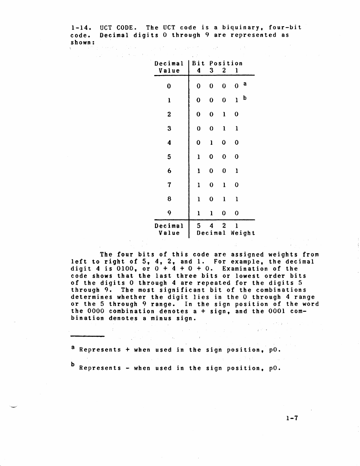
1-14.
OCT
CODE.
The
UCT
code
is
a
biquinary,
four-bit
code.
Decimal
digits
0
through
9
are
represented
as
shown:
Decimal
Bit
Position
Value
4 3 2 1
0 0 0 0 0 a
1 0 0 0 1 b
2 0 0 1 0
3 0 0 1 1
4 0 1 0 0
5 l 0 0 0
6 1 0 0 1
7 1 0 1 0
8 l 0 1 1
9 l 1 0 0
Decimal
5 4 2 1
Value
Decimal
Weight
The
four
bits
of
this
code
are
assigned
weights
from
left
to
right
of
5,
4,
2,
and
1.
For
example,
the
decimal
digit
4
is
0100,
or
0 + 4 + 0 + O.
Examination
of
the
code
shows
that
the
last
three
bits
or
lowest
order
bits
of
the
digits
0
through
4
are
repeated
for
the
digits
5
through
9.
The
most
significant
bit
of
the
combinations
determines
whether
the
digit
lies
in
the
0
through
4
range
or
the
5
through
9
range.
In
the
sign
position
of
the
word
the
0000
combination
denotes
a +
sign,
and
the
0001
com-
bination
denotes
a
minus
sign.
8
Revresents
+ when
used
in
the
sign
position,
po.
b
Represents
-when
used
in
the
sign
position,
pO.
1-7
Table of contents
Other Sperry Rand Desktop manuals


