Streacom FC9A User manual


Page
2 .................
3 .................
4 .................
5 - 6 ...........
7 - 8 ...........
9.................
10 ..............
11 .............
12-14 ..........
15 ..............
Contents
Index, Message, Introduction
Product Overview
Preparation for Assembly
Installing the Motherboard
Installing the CPU Cooler
Installing PSU & Other Accessories
Wiring Diagram
Installing Expansion Card (Optional)
Installing Drives
Final Adjustments, Replacing the Top Panel
A Message from the Streacom Team
IMPORTANT NOTICE
Passively cooled products can get hot to the touch, especially when systems are
running at high loads for extended periods. This is a normal part of their operation and
they have been tested to run safely under these conditions. Please take their
operational temperature into consideration when positioning and handling.
Thank you for choosing Streacom! In a market dominated by generic and uninspired products, we are on a mission to break the mold, not only of design, but
materials and finish. This is a value that is not easily conveyed in an industry preoccupied with specs and numbers, so your choice shows an appreciation and
understanding of what makes our products different, and we sincerely thank you for that.
Every care has been taken to ensure that this product meets the highest quality and standards we have defined. If anything about this product falls short of
your expectations or you have any questions that are not covered in this user guide, please contact us online at www.streacom.com/contact. We respond to
every question received and your feedback is a critical part of our ongoing product development and refinement.
From everyone at Streacom, we hope that you enjoy using our product!
COPYRIGHT NOTICE
Copyright © 2014 Streacom. All Rights Reserved. No part of this publication may be
reproduced, stored in a retrieval system, or transmitted, in any form or in any means –
by electronic, mechanical, photocopying, recording or otherwise – without prior
written permission. All trademarks and registered trademarks in this publication are the
property of their respective owners. Streacom is a registered trademark.
Introduction to Assembling Your Case
It’s not rocket science, but Streacom cases can be a little challenging to assemble at first because of the non traditional design and the materials used. Passive cooled
cases have an added layer of complexity because of the heatpipe assembly/hardware requirements, so please take the time to read the user guide and become
familiar with the components and assembly procedure. Additional information is also available on our website ‘system build guide’ page, and of course from our
support staff.
Below is a quick explanation of the different screws used in the assembly, and how they will be referred to throughout the guide. Screws are defined by head type,
e.g. ‘countersunk’ and by thread/size e.g. M3x5, and will be labeled with all that information, e.g. CS-M3x5
2
Pan Head Screw ( )PH
Hex Cheese Head Screw ( )HC
Countersunk Screw ( )CS
Thin Cheese Head Screw ( )TC PH-M3x5
PH
5mm
3mm
M(Metric)
Thumb Screw ( )TS
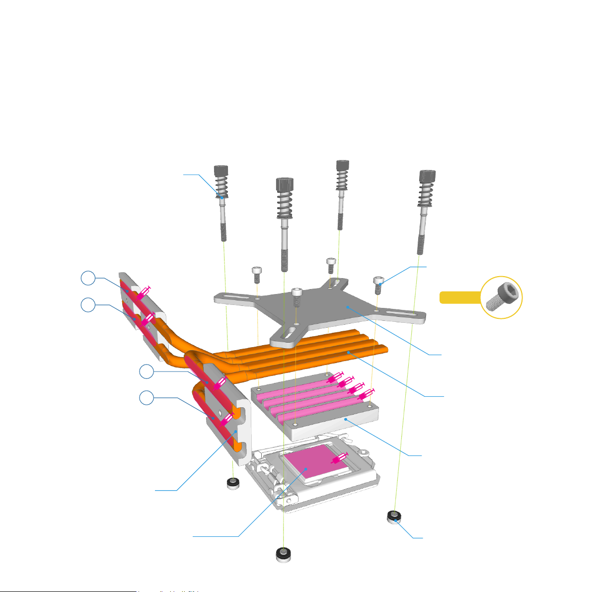
Also included in the kit.....
1 x Lower CPU Mount, 2 x Upper CPU Mount, 3 x Heatsink Connectors,
4 x Heatpipes, 4 x Spring-loaded Screws & Nuts, 1 x Allen Key, 2 x
Thermal Paste Tubes, Silicon Rubber Pads, Double Sided Adhesive Pads.
Tools you will need.....
Philips Screwdriver

Specification
Construction Material
Available Colours
Motherboard Compatibility
Hard Drive Support
Optical Drive Support
Cooling Method
Side Ports
Expansion Slot
Dimensions
Power Supply Support
IR Solution
Net Weight
Premium Grade Aluminum (6063)
Silver / Black - Anodized & Sandblasted Finish
Micro-ATX and Mini-ITX (Heatpipe Compatibility Dependent)
Minimum 1 x 3.5" + 2 x 2.5", Maximum 3 x 3.5" + 3 x 2.5" (Hardware Dependent)
1 x Slot Loading Optical Drive, Universal Eject Button*
Passive Convection/Radiation - 4 x Heatpipe Direct Touch (65W Recommended, 87 Max)
2 x USB 3.0, Left & Right Side (Optional USB2.0 Conversion Cable**)
3 x Low Profile Expansion Cards (Max Length, 156mm)
348 × 290 × 110mm (W×D×H, Including Feet)
NanoPSU (External AC Adapter + Internal DC to DC)** or ZeroFlex240 (Fanless Internal PSU)**
IRRC or FLIRC IR Solutions**
4.4KG (Excluding Heatpipe Assembly)
* FC9 Optical Version Only
** Not Supplied With Case
3
Top Panel
Heatsink Side Panel
Optical Drive Slot*
Heatsink Side Panel
Key Features
Heatpipe Assembly
Kensington Lock
I/O Shield Opening
Optical Drive Mounting Bracket* Drive Tray
USB3.0 Ports / Cable
DC Power Jack Hole
Heatsink Connectors
PCI Expansion Slots
Optical Drive Eject Button*
IR Window
Power Button
LED Power Light
Hidden USB 3.0 Port
USB3.0 Ports / Cable

Removing the Top Panel
The top panel is held in place by a total of 4 screws, 2 from each side of the
case which are accessible between the fins of the heatsink.
Remove all 4 screws and lift the top panel away from the case. There is a
cutout either side of the case to assist with lifting the top panel.
Open the Drive Tray
The drive tray has a swivel design that rotates upwards and towards the
front of the case. It is locked in place by 2 screws, I either side of the tray.
Remove these 2 screws and rotate the tray until it makes contact with the
front of the case. This will allow you full clearance inside the case so that
you can easily install the components.
If you have the Optical version of the FC9, you should also remove the
optical drive mounting bracket by removing the additional 4 screws as
shown.
4
Cutout
CS-M3 x 6
PH-M3x8
TC-M3x3
CS-M3x5

Preparation for Installing the Motherboard
The FC9 can accommodate a Micro-ATX or Mini-ITX motherboard and
depending on which one is used, the appropriate stand-offs should be
fitted to the bottom panel of the case. Note that the Mini-ITX stand-offs
are already fitted to the case as they are common to all motherboards.
The type of motherboard used will also determine the choice of other
internal components such as additional 3.5" hard drives and optional
internal PSU. Check your motherboard hole locations and fit the
appropriate stand-offs in the corresponding position on the bottom panel.
The stand-offs can be hand tightened in place.
mITX
mATX
Installing the I/O Shield
Locate the I/O shield supplied with your motherboard and firmly push it in
place. Ensure that it correctly seated otherwise the motherboard will be
difficult to install and not align correctly with the stand-offs.
5
HS-M3x7

Installing the Motherboard
Carefully lower the motherboard into the case, with the I/O port side
leading so that the ports can fit into the I/O shield.
When the motherboard is correctly in position, secure it to the case
stand-offs using the screws provided. Ensure that all the holes correctly
align with the stand-offs before fully tightening the screws. Also ensure that
you have installed the correct stand-off locations.
The CPU and RAM can no w be installed on the motherboard.
6
Fit the CPU Cooler Mounting Nuts
The 4 CPU cooler mounting nuts supplied with your case must be fitted
to the motherboard prior to installing it inside the case as they will be
required later on in the assembly to secure the CPU cooler assembly. The
nuts are held in place by adhesive pads which are supplied in a pack of 4
(there is a spare pack should you wish to change your motherboard in
future). Affix the adhesive pads to the CPU nuts in preparation for fixing
them to the motherboard.
With the motherboard turned upside down, located the CPU cooler
mounting holes. The hole position will vary depending on the brand and
model of CPU. Peel the protective film from the adhesive pads and stick
the nuts to the underside of the motherboard ensuring they correctly align
with the holes. The slightly raised rim of the nut should fit through the
motherboard CPU mounting holes.
CPU Cooler Mounting Nut
Adhesive Pads
Peel Protective Film
TC-M3x4

CPU Cooler Assembly
The passive CPU cooler assembly comprises of 3 main parts. The CPU mounts which fix the heatpipes to the CPU & motherboard, the heatsink connector blocks
that fix the heatpipes to the case side panel (heatsink), and the heatpipes that transfer the heat from the CPU to heatsink. Note that the heatpipes are numbered in
the plastic sleeves, 1 - 4 to assist with identifying them.
The use of thermal paste is ESSENTIAL to ensure efficient heat transfer and should be applied to ALL the surfaces indicated below.
We recommend first trying the assembly without applying thermal paste. This will allow you to test and adjust the alignment without making a mess with thermal
paste. Once you have a good approximation of the alignment, apply thermal paste initially between the lower CPU mount and heatpipes, then lock the heatpipes
between the upper and lower CPU mounts using the 4 HEX screws. With this assembled, you can now remove it from the case and apply thermal paste to the
CPU and heatsink contact side of the heatpipes.
Spring Loaded Screw
HEX Screw
Upper CPU Mount
© ©
Intel or AMD
CPU Mounting Nut
Heatpipe
Lower CPU Mount
CPU
7
HC-M3x6
1
3
4
2
Heatsink Connector Block

Carefully lower the heatpipe/CPU mount assembly into the case and place it onto the CPU, ensuring the heatpipes only make contact with the heatsink once the
assembly is resting centrally on the CPU. Fit the 4 spring loaded screws to the motherboard (into the CPU mounting nuts), but do not fully tighten yet.
Secure the heatpipes to the heatsink using the 3 connector blocks, which are screwed from the outside of the case (between the fins). If any fine adjustment is
required, you can loosen the 4 HEX screws on the CPU mount which will allow the heatpipes to slide.
Once you are satisfied with the alignment of the full assembly, you can fully tighten all the screws. The spring loaded screws should not be over tightened, and only
require 4-5 turns from the point the spring start to compress.
Warning! Do not forget to use
thermal paste, as this will result
in poor heat transfer and
potential CPU damage.
HC-M3x10
8
HC-M3x10

Install / Connect the Power Button, PSU, Optional IR & Other Cables
With the motherboard and CPU cooler installed, you can now connect the PSU and any other internal connections such as the SATA cables in perpetration
for installing the drives. For more details on installing the PSU and Optical IR, see the user guides supplied with those accessories.
Connect the front USB ports and the power button / light PCB to the motherboard, see diagram on next page for wiring details. The case is fitted with
USB3.0 ports which require an internal USB3.0 connector on the motherboard. If your motherboard does not have an internal USB3.0 header, it is still
possible to connect to the older USB2.0 header with a converter cable (not supplied with the case).
NanoPSU
IR PCB Power Button PCB
USB3.0 Port
USB3.0 Port
DC Power
Jack
9
PH-M3x5

Motherboard
Side USB Ports
Motherboard pinout and cable colours shown are for illustrative purposes only, actual layout and markings will
vary. Please check your motherboard user guide for full details and information.
When connecting the power LED, ensure correct polarity otherwise the light will not function.
If your motherboard does not have an internal USB3.0 header, it is still possible to connect to the USB2.0 header
using a converter cable sold separately. Using this converter will make the front USB ports 2.0 compatible.
USB 3.0 Connector
HDD+
HDD-
RESET
RESET
NC
LED+
LED-
PSW
PSW
NC
+5V
DA -
DA+
GND
N/C
USB2.0
USB 3.0USB 3.0
Optional Accessory for USB2.0
10
Power Switch / Light PCB

Fit the expansion card to case by carefully aligning it with the opening and
ensuring the lower side of the card bracket firstly slots in the gap between
the motherboard and case. Once the cards are in place, replace the PCI
mount then secure them to the PCI mount using the screws provided.
Installing PCI Card (Optional)
The FC9 supports 3 low profile expansion cards with a maximum length
of 155mm (without removing the drive tray). To install a card, first remove
the pre-installed PCI blanking plates by unscrewing it from the PCI mount,
then remove the PCI mount from the back of the case. It is secured in
place by 2 screws either side accessible from the inside of the case.
11
PH-M3x6 PCI Mount
PH-M3x6
CS-M3x6
PH-M3x5
CS-M3x6
PH-M3x6
PH-M3x5

Optical Drive Preparation
The OPTICAL version of the FC9, includes a drive mounting bracket which must be fitted to the drive prior to installing it onto the drive tray.
Secure the optical drive to the drive bracket using the 4 x 2mm screws supplied. The drive should be pushed as far forward as possible without activating the eject
button before tightening the screws. If the screws meet any resistance (from internal components of the optical drive), do NOT tighten that screw any further, it
could damage the mechanism. Once secured to the bracket, test the eject button can function correctly. Depending on the eject button position and height, a
rubber pad might need to be affixed between eject bar and drive eject button. The pads can either be applied directly to the drives eject button, or to the opposite
side of the eject button, or both sides, whichever gives the best result.
Slimline Slot Loading Optical Drive
Optical Drive Mounting Bracket
Optional Rubber
Pad Locations
Bottom Panel Drive Options
If you are using a Mini-ITX motherboard, there is also room to fit hard
drives to the bottom panel of the case. Drives are secured in place
through the pre-drilled holes in the bottom panel in the locations show.
Screws should be attached through the bottom of the case and into the
drive. Optional rubber pads can be used to raise the drive off the bottom
panel, reducing vibration and improving airflow.
These drive locations should be used as a secondary option and only if
there is no more room on the drive tray. Fitting drives to the bottom panel
can reduce airflow as the lower vents are blocked, and this should be
taken into account if using high TDP components.
12
PH-M2x2
CS-M3x8
CS-6#32
A
A
A
A
B
B
B
B
C
C
C
A
C
B
Eject Bar
Rubber Pads

Fitting Drives to the Lower Side of the Drive Tray
The lower side of the drive tray can accommodate a maximum of 1 x 3.5" drive or 2 x 2.5" drives.
The 3.5" mounting uses slots instead of fixed holes, to allow the drive to be fitted anywhere along the tray and with different orientations. The drive is secured to the
tray from the side using thumbscrews which fit through the slots and into the side mounting holes of the drives. The 3.5" drive should only be fitted after all other
drives are mounted to the tray.
If you prefer to use the lower side of the tray for 2.5" drives, they are secured to the drive tray using 4 screws per drive as shown below.
13
CS-M3x5
TS-6#32
3.5" Drive
2.5" Drive

Fitting Drives to the Upper Side of the Drive Tray
The upper side of the drive tray can accommodate a maximum of 3 x 2.5" drives or if you have the optical version of the FC9, 1 x 2.5" drive + 1 slimline optical
drive. As with the 3.5" mounting, the upper 2.5" drives use slots instead of fixed holes, to allow the drive to be fitted anywhere along the tray. The drives are secured
to the tray from below using 4 screws per drive.
If you have the OPTICAL version of the FC9, secure the optical drive to the drive tray with the 4 screws as shown, but DO NOT fully tighten the screws. Only after
you have closed the drive tray back into the case should these screws be tightened as you will need to adjust the position of the drive to line up with the front of the
case.
14
TC-M3x3
TC-M3x4
2.5" Drive
Optical Drive
2.5" Drive

Close and Secure the Drive Tray
With all the drives now fitted to the tray, return it to the original position
and secure it is place with a single screw each side of the tray. Power and
Data cables can now be connected to the drives.
Adjusting the Optical Drive
Adjust the position of the optical drive so its aligned with the inside
front of the case and the eject button protrudes about 1mm out from
the front of the case.
Test that the button operates correctly by listening/feeling for the
button ‘click’ when pressing the eject button.
Once the correct position has been found, tighten the 4 screws to
secure the optical drive in place.
CS-M3 x 6
Replace the Top Panel
With all the components installed, the top panel can now be replaced.
Prior to doing this, ensure that all cables are connected and all
components are securely fitted. Secure the top panel it in place using 4
screws, 2 from either side of the case, between the heatsink fins.
Connect Power & Other Cables
With the case now fully assembled, all that remains is to connect the
power and other cables.
When choosing a suitable place to position your case, please consider an
area with adequate air flow and a moderate room temperature, out of
direct sunlight.
15
CS-M3x5
PH-M3x8

Designed in Europe. Made in China. Copyright © 2014 Streacom. All Rights Reserved.
Table of contents
Other Streacom Desktop manuals