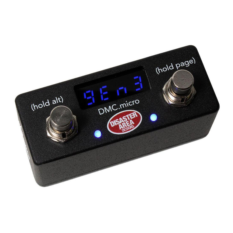
Disaster Area Designs DMC.micro PRO User manual

USER MANUAL
Contents
IntroductIon ..........................................1
Ins and outs...........................................1
setup Menu ............................................2
settIng up the dMc.MIcro ...................5
stryMon setup guIde ............................6
eventIde setup guIde.............................7
Boss setup guIde.................................8
chase BlIss setup guIde .......................9
lIne 6 setup guIde.............................. 10
MerIs setup guIde .............................. 11
alexander neo serIes setup guIde ... 12
eMpress setup guIde........................... 13
usB host Mode setup guIde ........... 14
custoM devIce setup.......................... 15
preset Mode ........................................ 16
devIce Mode........................................ 18
clock Mode......................................... 19
utIlIty Modes...................................... 20
looper Mode....................................... 21
MultIJack confIguratIon................... 22
DMC.micro PRO
DMC.micro PRO Manual Rev 1.00 04.11.2021
disasterareadesigns.com

Important Note:
This User Manual covers operation of both the DMC.micro PRO and the DMC.micro
running rmware version 2.0 or higher.
Throughout this manual we will refer to both the DMC.micro PRO and the older DMC.
micro as “DMC.micro.”
Special features available only on the PRO will be marked as “PRO FEATURE.”
Information pertaining to the older blue LED DMC.micro will be marked in BLUE or
referred to as LED4.
Specications
Size: 3.6”x 1.5” x 1.6” (93 x 38 x 42mm) excluding switch caps and jacks
5-pin MIDI Port (supports MIDI input with MIDI-Y cable)
MultiJack (supports expression pedal, dual footswitch, or MIDI output)
USB port (supports USB-MIDI or USB-HOST with gHOST Adapter)
Controls up to four MIDI devices
Power: 9V DC, 40mA or greater, center negative (not included)
Graphical OLED display (PRO) / 4-digit blue LED display (LED4)
Soft-touch footswitches
Preset, device, looper, clock, and UTIL modes
Recommended Accessories:
gHOST Adapter Cable Kit: Allows USB port to control USB-MIDI devices (C4, Zoom, etc)
Disaster Area MIDI Cables: High-quality space-saving right angle MIDI cables
Disaster Area MIDI-Y Cable: Convert DMC.micro MIDI port into MIDI IN and OUT
Disaster Area 5P-TRS PRO Cable: Connect MultiJack to 5-pin device or 5-pin port to 1/4”
device
All accessories available from disasterareadesigns.com/shop

1
Even though the DMC.micro is small, it features a ton of input / output capability!
The rear panel contains the ports as shown in the diagram below.
The MIDI port normally operates as an output - connect a standard MIDI cable between this
port and a MIDI-capable device to have the DMC.micro control it.
You can also connect our DMC MIDI Y-cable to this port to access both MIDI INPUT and OUT-
PUT, which allows you to control the DMC.micro from another device. We’ll cover this under
the Preset Expander section later.
Next up is the MultiJack - this versatile connector can perform many dierent functions
depending on the conguration of the DMC.micro. Some popular uses are MIDI output, ex-
pression pedal input, dual remote footswitch input, or even to send tap tempo to supported
devices!
Ins and outs
IntroduCtIon
The DMC.micro PRO is an updated and improved version of our most popular controller,
featuring full-sized performance in a much smaller package.
The DMC.micro user interface is incredibly simple – tap the left or right buttons to perform an
action, hold the left button to perform a third “alternate” action, or hold the right button to
advance to the next “page.”
In this manual we’ll explain all the functions of the controller, including helpful examples for
each page and setup type to help you get the most out of your rig.
We cover a TON of examples and setups in this manual but we have much more info on our
website - check out disasterareadesigns.com/support for more guides and info.
There’s also a USB port, which we use for rmware updates and USB MIDI to your DAW, iPad,
or other mobile device. It can also connect to certain other USB MIDI devices through our
gHOST adapter cable. For more info, please see the USB Host Mode Setup section on page 11.
Finally, we have a DC power jack. The DMC.micro requires 9V DC only, center negative, 2.1mm
pin. Just about anything that will power a Boss pedal will work on DMC.micro. You’ll need to
provide at least 100mA of isolated power, but more is okay.

2
setup Menu
All of the conguration and customization options are contained within the Setup Menu. Any
changes you make in this menu are saved in the memory of the DMC.micro for future use.
Throughout this manual we’ll indicate Setup Menu options as MENU = OPTION, meaning we’d
like you to navigate to that item in the Setup Menu and set its value to match.
HOLD TO
EDIT
NAVIGATING THE SETUP MENU:
Tap left or right to choose an item to edit.
Hold left to edit the item, then tap left or right to
change its value. PRO will highlight the menu item,
LED4 will ash the menu value.
Hold left to return to the main menu.
ENTERING THE SETUP MENU:
Press and hold both buttons after the DMC boots.
Release the buttons when you see SETUP on the
display.
HOLD TO
ENTER
Hold the right footswitch to save the settings and
exit.
If you have changed any of the port congurations,
be sure to power-cycle the DMC.micro.
TAP TO
MOVE
HOLD TO
SAVE
IMPORTANT NOTE: You must SAVE your changes from the Setup Menu before they will
take eect!

3
setup Menu (ContInued)
SETUP MENU ITEMS:
As you move through the menu you’ll see the following items to edit. Feel free to tweak the
settings to your satisfaction, but if you’re not sure about anything we recommend the default
settings as listed. The menu names for the DMC.micro LED4 are shown in BLUE.
MAX PRESET / PRST: Number of presets available in Preset mode. If PRST is set to OFF, preset
mode will be disabled. Range OFF to 99, default 16.
PRST CHAN/ P CH: Sets the channels the DMC will send using Preset Mode. Set A, B, C, D to
send on channels 1, 2, 3, 4. Set any channel to 0 to disable sending on that channel.
DEVICES / DEV: Number of available device modes. Each device mode controls one MIDI
device on channels 1-4 (devices A-D.) Range OFF to DevD, default DevA.
DEVICE A / DEV.A Device mode assignments. Select the device type assigned
DEVICE B / DEV.B to each channel of the controller to automatically set up the
DEVICE C / DEV.C correct MIDI commands for each device.
DEVICE D / DEV.D
UTIL MOD X / UTIL.X Enable or disable Utility Mode X
UTIL MOD Y / UTIL.Y Enable or disable Utility Mode Y or Looper Mode. Set this to DevA-
DevD to assign the looper controls to that device.
CLOCK MODE / CLK: Enable or disable the Clock Mode. Set this to OFF to disable, Preset
(new tempo loads for each preset) or Global (one tempo for all presets)
UTIL MOD X / UTIL MOD Y: Congure the functions the DMC will use for Utility Mode X and Y.
Please consult the Utility Mode section on page 20 for further details. Note: these menu items
will be hidden if Utility Modes are disabled.
MULTIJACK / JACK: Congures the MultiJack hardware, please see the MultiJack section on
page 22 for full details.
EXP: Jack connects to expression pedal (TRS type required)
FT.SW: Jack connects to single foot switch for tap tempo
N-O: Jack functions as normally-open tap tempo output*
MIDI TIP / MID.T: Jack sends MIDI from tip
MIDI RNG / MID.R: Jack sends MIDI from ring
MIDI T&R / MD.TR: Jack sends MIDI from both tip and ring
MIDI I/O / MD.IO: Jack sends MIDI from tip, receives MIDI from ring
UTIL: Connect dual footswitch to jack OR expression pedal, control functions
programmable using UTIL J TIP and RING functions
N-C: Jack functions as normally-closed tap tempo output*
Functions marked * require the jack DIP switches to be set to OFF-OFF-OFF
JACK CHAN / J CH: Sets the MIDI channels that the MultiJack will send.
J TIP / J RNG: Congure the functions the MultiJack footswitches or expression pedal will
send. Please consult the MultiJack section on page 22 for further details. Note: these menu
items will be hidden if MultiJack is not set to UTIL.
TAP LENGTH / TLEN: Congures the MultiJack tempo output. Longer settings increase the
time the output is held after a tap, increase this if your tap tempo device doesn’t respond to
taps. Only controls the MultiJack in N-O or N-C modes, does not aect any other settings.
(continues next page)

4
setup Menu (ContInued)
HOLD TIME / HOLD: Congures the time needed to trigger the “hold” functions for the
DMC footswitches. Set this to LO to trigger holds faster, or set to HI if you are experiencing
unwanted holds.
USB MODE / USB: Congures USB port function.
MIDI = your computer or mobile device controls DMC.micro
HOST = DMC.micro controls your class-compliant USB MIDI device
INPUT CHANNEL / INCH:MIDI channel the controller will use to receive incoming data.
Default is 16. MIDI input on DMC.micro requires the use of the Disaster Area MIDI-Y cable.
MIDI THRU / THRU: Enable or disable MIDI thru on the DMC interfaces. MIDI data from each
interface is always passed to the others, THRU setting determines whether that same data is
returned on the same interface. In most cases, this should be set to OFF or 5 P.
OFF: No MIDI data will pass from input to output on any interface
5 P: MIDI data coming in from the DIN port will be passed to the DIN port
JACK: MIDI data from the MultiJack will pass back through the MultiJack
ALL: MIDI data from DIN, USB, and Jack will pass back out those interfaces
USB: MIDI data from USB port will be mirrored back to USB port.
NAME DISP (PRO): Enable preset name display
OFF: Show preset number only
NAME & NUM: Show preset name and number on two lines
BIG NAME: Show rst 7 letters of preset name in large font
UTIL NAME (PRO): Display 5-character names for each Utility Mode function.
UTIL LOAD / UT.LD: Load the UTIL mode values per preset for either Util X, Y, or both. Please
consult the Utility Mode section on page 20 for further details.
BRT:Sets display brightness from 0-9. Default is 4. Only available on LED4 version.
CUST 1, CUST 2 / C1, C2: Congure the two Custom MIDI devices here. Please consult the
Custom Devices section on page 15 for full details. Note: these menu items will be hidden if
neither of the Custom devices is selected in any device slot.
DUMP: Preset and conguration dump via MIDI SysEx.
FACT: Factory reset. Tap RIGHT in this menu until a setting is displayed,
then tap the left button to reset those settings to defaults.
ALL = clears conguration, lls presets from 0-99.
PROD = test mode, used at the factory.
C4 = sets up Device A and the USB port for use with the Source Audio C4. Does not
erase preses or change other cong items.
MERS = sets up Device A and the MultiJack for use with the Meris pedal lineup.
Will not erase presets or change other cong items.
CBA = sets up Device A and the MultiJack for use with a single Chase Bliss pedal.
Does not erase presets or change other cong items.

5
settIng up the dMC.MICro
So now that you know what all the setup menu options are, how do you actually set this
controller up to work with your rig? We’ll cover the general steps and provide an example
conguration to get you started.
First, gure out what MIDI devices and other pedals you want the DMC.micro to control, and
verify that they are on the Supported Devices List here:
disasterareadesigns.com/supported-devices
If you don’t see your device listed, check out the Custom Devices section on page 15.
In our example, we’ll be controlling a Meris Enzo and a Strymon Timeline.
Enter the setup mode on the DMC by holding both of its buttons and navigate to the
DEVICES menu. Since we have two MIDI devices, we’ll set this to DEV B, which means we’ll be
using devices A and B.
Next, we’ll set up each device slot on the DMC.micro to talk to the correct device, which will
congure the DMC to send the correct commands. We’ll be using the Enzo as device A and
the Timeline as device B, just based on the order that they are in our example signal chain,
but you can assign them in whatever order seems correct to you. Set DEVICE A = MERIS and
DEVICE B = TIMELINE.
Then we need to consider how we’ll connect each device’s physical MIDI interface to the DMC.
micro. The Timeline has a dedicated 5-pin MIDI port, so the most reasonable thing to do
would be to use a MIDI cable to link them up. But the Enzo has a 1/4” jack for expression, MIDI,
or tap tempo - so we’ll need to either use an adapter cable from the Timeline’s MIDI output or
connect the Enzo directly to the DMC using the MultiJack.
In our example we’ll be using the MultiJack, since it doesn’t require any extra hardware and
can just use a standard patch cable, but if you wanted to use the MultiJack for an expression
pedal then the adapter from the Timeline’s MIDI port would be a good choice.
Set MULTIJACK = MIDI TIP and while you’re at it, verify that the DIP switches on the bottom
of the DMC.micro are set to ON-ON-ON.
If you want to control the looper on the Timeline, congure UTIL MOD Y = LOOPER B.
Then after everything is congured as detailed above, hold the right button on the DMC to
save and exit.
Follow the instructions on the following pages to set up your Enzo and Timeline using their
conguration menus - make sure that the Enzo is set to MIDI channel 1 and the Timeline to
channel 2.
Finally, have fun with it! Read up on the descriptions of Preset, Device, and Looper modes
in the next few pages to get a handle on what everything does. Check out the Looper and
Clock Mode sections for more ideas about getting the most out of your DMC.micro with your
particular rig. And be sure to visit the Utility Mode section for details on adding even more
control possibilities to your setup!
The next new pages cover the most common pedals that our users connect to the DMC.
micro, as well as a few that are less common but more dicult to congure!

6
stryMon setup guIde
The DMC.micro supports three “families”of Strymon MIDI devices:
Big-Box with Display: Timeline, Mobius, BigSky have dedicated 5-pin MIDI
Big-Box, no Display: Volante, NightSky have dedicated 5-pin MIDI and 1/4”MIDI
Small-Box: Sunset, Riverside, Iridium, Compadre use 1/4” with the MultiJack or adapter cable
Timeline, Mobius, BigSky: Use the dedicated device driver selections for these.
Enter the Globals on your pedal and congure MIDITH = ON or MERGE, MIDICH to match the
device slot you have selected. Ex. DevA = MIDICH 1, DevB = MIDICH 2, etc.
If you plan to use the Clock mode to send MIDI clock to your device, set MIDICL = ON (this may
also be in the PARAMS menu depending on the pedal) and MC SWP = OFF if applicable.
If you are using the Timeline and wish to use the DMC to control its looper, congure BYPASS =
BUFBYP, LPEXIT = PLAY.
Mobius may be set to BYPASS = TRUEBYP, but Timeline and BigSky should be set to BUFBYP in
order to maintain trails.
Volante, NightSky may use the BigSky device driver. Each pedal has a slightly dierent method
to set its MIDI channel, consult the device manual for your pedal for information about setting
the channel. Remember that DevA = channel 1, DevB = channel 2 etc.
Volante and NightSky are not set to receive MIDI clock by default and must be congured to do
so per-preset.
Note: Volante SOS Looper is not yet supported
Small-Box pedals use their 1/4”EXP or FAVORITE jack for MIDI. Each pedal has a slightly
dierent setup for conguring its MIDI channel so consult your device manual for more details.
If you’re using the MuliJack to interface to a Strymon Small-Box pedal, connect the DMC to the
pedal using a standard TRS or TS cable and ip the DIP switches to ON-ON-ON. Then congure
JACK = MIDI TIP and make sure that JACK CHANNEL is set to include the device slot you’re
using for your Strymon pedal. For example, if you are using DevC for an Iridium, you would
congure JACK CHANNEL = -B-- or ABCD. Any setting that has your chosen channel active
should work.
Sunset has a slightly dierent bypass conguration than the other Small-Box pedals. We
recommend that you set preset 0 on the Sunset with knobs at minimum and both sides of the
pedal bypassed, then save. The DMC.micro will use preset 0 as its bypass setting, allowing you
to easily bypass both sides for clean sound.

7
eventIde setup guIde
The DMC.micro supports three “families”of Eventide devices:
H9 / Factor: H9, Timefactor, Modfactor, Pitchfactor, SPACE
Rose
Stompbox Series: Pedals using Eventide Device Manager, including Blackhole, UltraTap,
MicroPitch
H9 and Factor devices: Select the H9 device driver for the device slot you wish to use.
Eventide devices have a robust MIDI mapping capability, but none of their functions are
set from the factory. In order for these devices to recognize the commands we send, a few
parameters must be set in their MIDI menus
If using H9 Control, navigate to Pedal -> MIDI Settings -> MIDI Channel
Set MIDI Receive Channel match device selection - 1 for DevA, 2 for DevB, etc.
Navigate to Pedal -> MIDI Settings -> Assign MIDI CC Messages. Map Tap Tempo to MIDI CC 44
Map Performance Switch to MIDI CC 46
Map Toggle Tuner to MIDI CC 69
Map Activate to MIDI CC 42
Map Set Expression Pedal Value to CC 48
If using the MIDI menu on the device itself:
Navigate to RCV CHANNEL and set to match device selection - 1 for DevA, 2 for DevB, etc.
Navigate to the RCV CTL menu and set the following:
TAP C42 HOTSW C46 ACTIVE C42 PEDAL C48
If you plan to use the looper on the H9 or Timefactor, set the following:
Looper - Record MIDI CC 87
Looper - Play MIDI CC 86
Looper - Stop MIDI CC 85
Looper - Empty MIDI CC 90
Looper - Flip Direction MIDI CC 94
Looper - Flip Octave MIDI CC 95
Rose: Select the EVEN. ROSE / ROSE device driver for the device slot you wish to use. Connect
the Rose EXP jack using a TRS cable, set MULTIJACK = MIDI TIP and JACK CHAN active for the
device slot you are using. Set the DIP switches to ON-ON-ON.
Power on the Rose and hold active + φ, then click the PRESET button until the 4th LED is lit.
Click the shape button to set the MIDI channel, the Rose defaults to channel 1.
CH1 = LED5, CH2 = LED4, CH3 = LED 4+5, CH4, LED3.
Click the φ button to enable or disable MIDI clock (LED5.)
Hold the active footswitch to save and exit.
EDM Series: Select the EVEN STOMP / E.STP device driver for the device slot you wish to use.
Connect the pedal EXP jack using a TRS cable, set MULTIJACK = MIDI TIP and JACK CHAN
active for the device slot you are using. Set the DIP switches to ON-ON-ON.
Power on the pedal while holding the active footswitch and V button to enter system setup.
Tap the V button until the 4th LED is lit (MIDI BOX.) Then press the tap button to set the MIDI
channel. The default is OMNI (all ve LEDs,) but the pedal needs to be set to a channel between
1 and 4. CH1 = LED5, CH2 = LED4, CH3 = LED 4+5, CH4, LED3. Tap the active footswitch to
enable or disable MIDI clock (all ve LEDs light when enabled.) Power cycle the pedal to save
and exit.

8
Boss setup guIde
The DMC.micro supports the following Boss pedals:
500 Series: DD-500, MD-500, RV-500
200 Series: DD-200, OD-200, GE-200
Slicer SL-20 (MIDI Clock only!)
Boss 500-Series pedals have full-sized DIN connections for MIDI connections. Select the
correct device driver to match your pedal in the DevA-DevD menu, ex. DevB = Boss DD500.
To congure the pedal, enter the MIDI menu by pressing EDIT, press down to select MIDI, and
press EDIT again.
Set Rx Channel to match the device slot you have chosen for the Boss pedal, ex. DevA = CH1,
DevB = CH2.
Set PC OUT = o, Bank Sel Out = OFF, MIDI IN->OUT = MIDI, SYNC = MIDI
To use the DMC.micro to set the tempo on the 500-Series, we recommend enabling the Clock
mode as shown on page 19.
The default settings should be correct but if you have problems controlling the pedal, enter the
MIDI mode again and ensure that the following are set:
DD-500: Eect On / O CC = 21, EXP CC = 16
MD-500: Eect On / O CC = 27, EXP CC = 16
RV-500: Eect On / O CC = 27, EXP CC = 16
Boss 200-Series:
All of the pedals in this series have the same MIDI implementation. Please ensure that your
200-series pedal is updated to the latest rmware from the Boss site to enable full MIDI control.
Congure the device slot you wish to use for your Boss pedal as Boss 200 / BOS2. Ex. DevD =
Boss 200. Congure MULTIJACK = MIDI TIP / MID.T and set JACK CHAN / J CH to match the
device slot you have selected, ex. JACK CHAN = CH D.
Ensure that the DIP switches on the DMC.micro are set to ON-ON-ON.
Connect your Boss pedal’s 1/8”MIDI input to the MutliJack using a 1/4”to 1/8”TRS cable
Enter the 200-series settings menu by holding the two buttons above the footswitches, ex. TAP
DIVISION and MEMORY on the DD-200.
Turn the data knob to select a parameter, then press it to select and change that parameter. On
the DD-200 this is the TIME knob.
Congure rCH to match the MIDI channel for your chosen device slot, ex. DevA = CH1, DevB =
CH2.
Congure tCh = OFF, Pin = ON, Pot = OFF, CCi = ON, CCo = OFF, EPC = 16, EFC = 27, SYn =
Aut, Nth = ON
Save and exit by holding both buttons down.

9
Chase BlIss setup guIde
Hold and release the right footswitch on the DMC.micro until the device mode that you want to
use is showing. As an example, we’ll congure a Chase Bliss MOOD pedal as DevA.
Navigate to where you want to start - using our example with MOOD, this would be the A
device mode. The display should show “A”followed by the preset
number.
Power on the Chase Bliss pedal while holding both of its footswitches.
Release when you see the pedal power on.
Tap the left or right footswitches on DMC.micro until you see the center LED on your CBA pedal
change colors.
That’s it - your Chase Bliss pedal is now congured!
The large Automatone series pedals connect directly to the DMC.micro using a standard MIDI
cable. Set the pedal MIDI channel to match the device slot you wish to use, ex. devA = CH1,
devB = CH2.
For the smaller Chase Bliss pedals that use 1/4” cables for MIDI, enter Setup on the DMC.micro
and congure JACK = MIDI RNG / MID.R,and make sure that the DIP switches on your DMC.
micro are set to ON-ON-ON.
For either type of pedal, set one or more of your device slots to CHASEBLISS / CBA.Save and
exit Setup mode. If you are connecting a compact Chase Bliss pedal please continue to the next
steps.
Connect your Chase Bliss pedal to the DMC.micro using a TRS cable,
leave the CBA pedal powered OFF.

10
lIne 6 setup guIde
The DMC.micro supports several Line 6 devices:
M-Series: M5, M9, M13
HX Series: HX Eects, HX Stomp
To congure any supported Line 6 device to work with the DMC.micro, rst congure the
controller with the correct device driver for the device slot you wish to use. For example, to use
an HX Stomp as device A, set DEVICE A = HX Stomp.
Then, set up the MIDI receive channel on your device to the matching MIDI channel.
For HX Stomp and Eects, enter the global menu and set:
MIDI Base Channel to match - for example DevA = CH1, DevB = CH2.
MIDI THRU = ON
Rx MIDI Clock = MIDI IN or AUTO
MIDI PC Rx = ON
For M-Series, enter the Prefs menu and set:
Manual Save
MIDI CH to match your device slot selection, for example DevA = CH1, DevB = CH2.
HX Stomp users please note that the default expression pedal commands send EXP1 or PEDAL1,
so you’ll need to use this conguration rather than assigning the pedal to a single command.
You can use MULTIJACK = UTIL, then assign J TIP TYP = an unreserved MIDI command if you
want to assign the pedal to a single function.
The DMC.micro Looper mode can control the looper in the M9, M13, HX Stomp, or HX Eects.
The M5 does not have a looper and is not supported for looper control.
The M9 and M13 loopers are always accessible, and run “in the background”regardless of which
scene is selected on the pedal. Simply set the UTIL MOD Y = LOOPER to match the device slot
you’ve chosen for your M-series pedal. For example if your M9 is set to DevB / Channel 2, then
set UTIL MOD Y = LOOPER B.
The HX Stomp and Eects loopers require you to have one block of your preset set to the
Looper. You’ll then need to congure the UTIL MOD Y = LOOPER to match the device slot you’ve
chosen as detailed above. You can use the looper on the HX series regardless of where it is in
the patch and whether you’re in a mode that allows access to its controls or not.

11
MerIs setup guIde
To congure your Meris pedal with DMC.micro, plug in a TRS / mono cable from the MultiJack
on DMC.micro to the EXP / MIDI jack on the back of the Meris. Alternatively you can use a
5P-TRS PRO cable to connect from the DMC.micro MIDI port to the Meris EXP / MIDI jack. This
conguration will allow you to use the DMC.micro MultiJack to connect to an expression pedal.
Enter Setup on the DMC.micro and congure MUKTIJACK = MIDI TIP to connect with TRS cable
or EXP if you’re using a MIDI cable. Set your desired device mode to MERIS. Remember to hold
the right footswitch to save. Set the DIP switches to ON-ON-ON.
Example: If you want to use a Polymoon as your B device,
connected to the MultiJack, set DevB = MERIS,
JACK = MIDI, JACK CHAN = CH B
Power on the Meris pedal while holding the LED button over the left footswitch. All of the
Meris LEDs will blink three times to indicate that it is now in setup mode.
Rotate the lower right knob fully CLOCKWISE to set the EXP jack to MIDI. The far right small LED
will light to indicate MIDI mode.
Rotate the lower middle knob to set the desired MIDI channel - the LEDs on the pedal will light
to show the MIDI channel as you turn the knob. Example: To set the pedal to MIDI channel 2
(DevB,) turn the lower right knob until the lower small LED on the right side is lit.
01
02
03
04
05
06
07
08
09
10
11
12
13
14
15
16
Power your Meris pedal o and back on to save the conguration.
Your Meris pedal is now congured!

12
alexander neo serIes setup guIde
To congure your Alexander Neo pedal with DMC.micro, plug a TS / mono cable from the
MultiJack on the DMC.micro to the MultiJack on the left side of your Neo pedal. Yes, we know
they’re both called MultiJack, we made them both :)
Enter Setup on the DMC.micro and congure JACK = MIDI RNG / MID.R, then set one or more of
your device slots to ALEXANDER / ALEX. Save and exit Setup mode, then make sure that the DIP
switches on your DMC.micro are set to ON-ON-ON.
Example: If you want to use a Syntax Error as your third MIDI device you would
set DevC = ALEX in the DMC.micro Setup menu.
Power the DMC.micro on, but leave the
Neo pedal o.
Hold and release the right footswitch on the DMC.micro until the device mode that you want to
use is showing.
Example: Navigate to the C device mode - C plus a number will show.
Power on the Neo pedal while holding its center select button.
Release the button when the main LED turns violet.
Tap the center button until the upper small LED is red, then hold Select to
save.
Power the Neo pedal o and back on, again holding the center button until the upper LED turns
violet.
Tap the left or right buttons on the DMC.micro until you see the upper small
LED ash, then hold the select button to save and exit.
Your Neo pedal is now congured!

13
eMpress setup guIde
To congure your Empress Reverb or Echosystem pedal with DMC.micro, plug in a TRS / mono
cable from the DMC.micro MultiJack to the Control Port on the back of the Empress pedal. Be
sure that the MultiJack DIP switches are set to ON-ON-ON.
Enter Setup on the DMC.micro and congure JACK = MIDI TIP. Set your desired device mode to
EECO (Echosystem) or EMPR (Reverb.) Remember to hold the right footswitch to save.
Example: If you want to use an Empress Reverb as your D device, you should set DevD = EMPR
REVB, MULTIJACK = MIDI TIP, JACK CHAN = CH D.
Enter the Advanced Conguration mode on the Empress pedal by holding the Select and
Bypass footswitches, then pressing the Save button. The preset LEDs on the Empress pedal will
blink yellow twice to indicate that you are in Advanced Conguration Mode.
Rotate the mode selector knob until the second mode LED lights (plate or tape) then turn the
upper left knob (decay or delay time) until the fth preset LED lights blue.
1
2
1
HOLD
Then rotate the mode selector knob to the seventh mode LED lights (ambient swell or ambient,)
and then turn the upper left knob to select the MIDI channel. The preset LEDs will light to show
the MIDI channel from 1 to 16. Example: To set the Reverb to MIDI channel 4 (DevD), turn the
decay knob until the fourth preset LED lights blue.
Hold the Select and Bypass footswitches to save and exit Advanced Conguration mode.
Your Empress pedal is now congured!
01 02 03 04 05
06 07 08 09 10
11 12 13 14 15
16
PRESS HOLD

14
usB host Mode setup guIde
(Zoom, Red Panda, SouRce audio)
DMC.micro supports controlling one USB MIDI device on MIDI channel 1. To connect a USB MIDI
pedal to DMC.micro, you’ll need a USB cable that matches the type on your pedal and a Disaster
Area gHOST Adapter Cable.
Enter Setup on the DMC.micro and congure USB as HOST.
Then set up the A device as a supported device type.
At this time, DMC.micro supports Zoom MultiStomp pedals (MS-50G, MS-60B, MS-70 CDR) as
ZOOM, Source Audio C4, Spectrum, Ultrawave as C4, Red Panda Tensor as TENS, or Red Panda
Particle v2 as PRT2.
Example: If you want to connect an MS-70CDR, set DevA = ZOOM and USB = HOST.
Save the conguration and exit.
Power o the DMC.micro and your USB MIDI device.
Plug the gHOST Adapter Cable into the USB port of the DMC.micro.
Plug the USB cable into the USB port of your MIDI device.
Connect the gHOST Adapter Cable to the USB cable.
Congure your USB MIDI device to use MIDI channel 1. The Zoom MS series are automatically
congured. Source Audio C4, Spectrum, Ultrawave devices should also set Skip USB Power
Check to ON in the Neuro App / Desktop editor.
Power on both devices. The Preset Mode and A device modes should both control your USB
MIDI device.
USB HOST MODE TIPS:
DMC.micro can only control ONE USB MIDI device, USB hubs aren’t supported.
Only Device A can use USB MIDI! If you need additional USB MIDI devices, check out the
micro.ghost USB MIDI adapter.
USB MIDI devices may be more susceptible to noise pickup than 5-pin or 1/4” devices. We
generally recommend either of those connection methods if at all possible.
Alexander Neo Series and Super Series pedals are NOT supported using USB. Please use the 1/4”
jacks to control them instead.
If you have to use USB MIDI and are experiencing unwanted noise from your device, make sure
that both the DMC.micro and your device are on separate power outputs or supplies.

15
CustoM devICe setup
So what happens if your device(s) aren’t supported? Does that mean you can’t use them with
the DMC.micro?
Not at all! You can use the GEN MIDI or GEN MIDI 2 device driver, which provide basic
functionality for devices that don’t support full MIDI control. GEN MIDI allows you to select
programs 0-127, send CC4 over expression pedal, and send CC64 for tap tempo. When you use
the Device Mode Bypass command, the DMC.micro will send program 0, so you can set this
patch up on your device with a neutral or bypassed setting. GEN MIDI 2 does the same things
but does not send program change 0 for bypass.
GEN MIDI and GEN MIDI 2 work great for older rack gear, synths, or processors that are
designed around MIDI program changes, without a lot of extra controls available. These device
drivers will get you going with a minimum of fuss.
Okay, that’s great but what if you have a device that does support controls for bypass, tap
tempo, expression, etc? Maybe it’s the hot new pedal and you don’t want to wait for us to add
support in a rmware update? No problem - create a Custom Device and get playing!
Enter Setup and congure one or more of your device slots as CUSTOM 1 or CUSTOM 2
(CST1 / CST2.) This will enable the Custom Device menu options in setup. We’ve listed the
conguration items for CUSTOM 1 but the items for CUSTOM 2 are arranged the same way.
CUST 1 MIN / C1LO Set this value equal to the lowest number preset your device needs.
Usually zero.
CUST 1 MAX / C1HI Set this value to the highest number preset your device accepts. This varies
a lot, for example Meris and Alexander devices max out at 16 but Chase Bliss go to 122.
CUST 1 BYP / C1BP Congure this for the MIDI CC number your device uses for bypass. For
example, many devices will use CC22 or CC102 for this number. The DMC will manage the
values needed to turn on or o for you.
CUST 1 TAP / C1TT Set this to the MIDI CC number your device uses for tap tempo, if
available. CC93 and CC64 are common values.
CUST 1 EXP / C1EP MIDI CC value your device uses for the expression pedal input, if available.
You can also set this to any MIDI CC value you like, if you want the expression pedal on the DMC.
micro to control a certain parameter on your device.
CUST 1 DSP / C1DS This sets how the Device Mode screen will show the preset numbers for
your device. This is purely cosmetic, it just helps to make the DMC display match your device!
0-127 / 0Presets are displayed starting at 0 and ending at 127
1-128 / 1Presets are displayed starting at 1 and ending at 128
BANK2 / BN-2 Presets are displayed in banks of 2, ex. 00A, 00B, 01B
BANK3 / BN-3 Presets are displayed in banks of 3, ex. 00A, 00B, 00C, 01A
BANK3.1 / BN3.1 Presets are displayed in banks of 3 starting at 01A.
If your device doesn’t support one or more of these commands, set that option to ZERO to
prevent the DMC from sending that command.
NOTE: The CUSTOM 2 / CST2 device is congured identically to CUSTOM 1 / CST1, you can
set up two dierent devices. You can also use either device in as many slots as you like - want
four copies of CUSTOM 1? How about two each of CUSTOM 1 and CUSTOM 2? No problem, go
nuts!

16
preset Mode
Preset mode is the heart of the DMC.micro. You’ll probably spend most of your time here, so
we should get to know it!
If your DMC.micro doesn’t show “P” plus a number on the display, then long-hold the right
button to return to preset mode.
Now that you’re in preset mode, try tapping the left and right buttons. You should see the
display change to show that you’ve selected new presets and your connected devices are
probably changing their sounds, too! So far, so good, so what’s the point?
The point is that preset mode allows you to access any sound on any device, in any
combination, all with a single tap of your foot!
To edit and save a preset, just follow these simple steps:
TAP
HOLD
TAP
Tap the left or right buttons to
select the preset you would
like to edit.
Hold the right button to
advance to the rst device
mode (Dev A).
Tap the left or right buttons to
select the sound you want to
use on the selected device.
If you want to bypass this
device, hold the left button.
HOLD TO
BYPASS
HOLD
LONG
HOLD
Hold the right button to
advance to the next device
mode and select a new sound.
Repeat until you return to
preset mode, or long-hold
the right button to go back
immediately.
Hold the left button to save the
preset!
HOLD TO
SAVE

17
preset Mode (ContInued)
The DMC.micro PRO also allows you to name each preset, for easy identication later.
Each preset name is 8 characters and may include upper and lower-case text, numbers,
punctuation, and symbols.
To enable preset names, enter the Setup menu and congure NAME DISP = NAME & NUM or
NAME LRG, then save and exit Setup.
NAME & NUM divides the display into two medium-
sized lines, one with preset name (8 characters)
and one with preset number + clock settings, if
applicable.
NAME LRG shows the preset name in large text (7
characters) and the preset number + clock settings
in small text underneath.
EDITING A PRESET NAME:
Enter Preset Mode and select the preset whose
name you would like to change.
Hold the left button to save the preset, and keep it
held until NAME EDIT appears on the screen.
Tap the left or right buttons to select a character
to edit, shown by the highlighted cursor on the
display.
Hold the left button to edit the selected character,
the cursor will ash. Tap left or right to change the
character.
Hold the left button to stop exiting the current
character, then repeat these steps until all
characters are correct.
Hold the right button to save the preset name and
exit the Name Edit mode.
HOLD TO EDIT
TAP TO SELECT CHARACTER
HOLD TO EDIT SELECTED,
TAP TO CHANGE
HOLD TO SAVE NAME

18
devICe Mode
Device mode lets you scroll through all of your connected devices, change their patches /
sounds, and bypass or engage them.
It’s a quick way to make changes on your pedals, and we also use it to edit the settings for
preset mode.
Hold down the right footswitch from preset mode to enter the rst device mode (DevA).
If you’re already in a device mode, hold the right footswitch to move to the next device mode
(DevB, DevC, etc.)
HOLD TO ENTER
Once you are in device mode, the DMC.micro changes from controlling all of your devices at
the same time to controlling only the selected device.
HOLDTAP
Hold the right button to
advance to the next device
mode (Dev B.)
Repeat to edit all of your
devices.
Tap the left or right buttons to
select the sound you want to
use on the selected device.
If you want to bypass this
device, hold the left button.
HOLD TO
BYPASS
LONG
HOLD
Repeat to scroll through all
of your remaining devices, or
long-hold the right button
to go back to Preset mode
immediately.
LONG
HOLD
HOLD
BOTH
You can also use Device mode to help
you save presets on your Chase Bliss
Audio or Red Panda pedals.
Select the location of the sound you’d
like to save in the DMC.micro Device
mode.
Turn the knobs and move the DIP
switches on your pedals, and when you
get the sound you want, hold both of
the footswitches on the pedal.
Long-hold the left footswitch on DMC.
micro to send over the MIDI message
to save.
The center LED (Chase Bliss) or green
LED (Red Panda) will ash to show that
it has saved the new sound.
Table of contents
Other Disaster Area Designs Controllers manuals
Disaster Area Designs
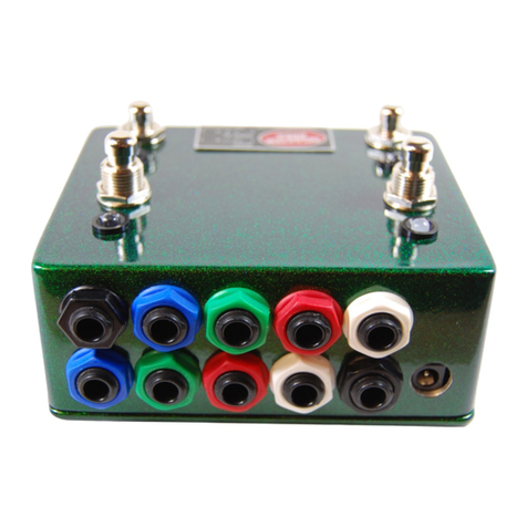
Disaster Area Designs DMC.micro User manual
Disaster Area Designs
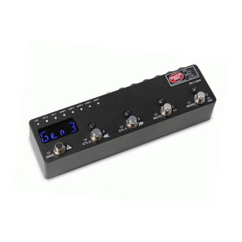
Disaster Area Designs DPC-4EZ User manual
Disaster Area Designs
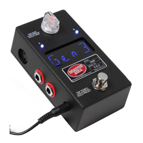
Disaster Area Designs DPC-5 Gen3 User manual
Disaster Area Designs
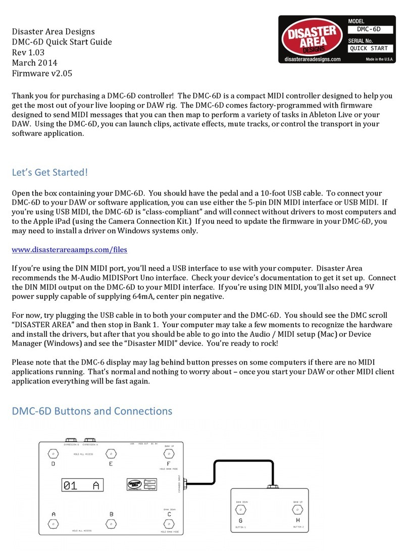
Disaster Area Designs SMARTClock Gen3 User manual
Disaster Area Designs
Disaster Area Designs DMC-6D User manual
Popular Controllers manuals by other brands
GS
GS Chromalox 4081 Installation & operation manual
Daikin
Daikin ECFWEB6 Installation and operation manual

Aerotech
Aerotech APR100DR Series Hardware manual
Digifort
Digifort DGF-KB1000 Quick installation guide

Chargery
Chargery BMS8T Series owner's manual
Furious FPV
Furious FPV RACEWHOOP Manual user instructions
