4
1.3 Warnings and General Safety
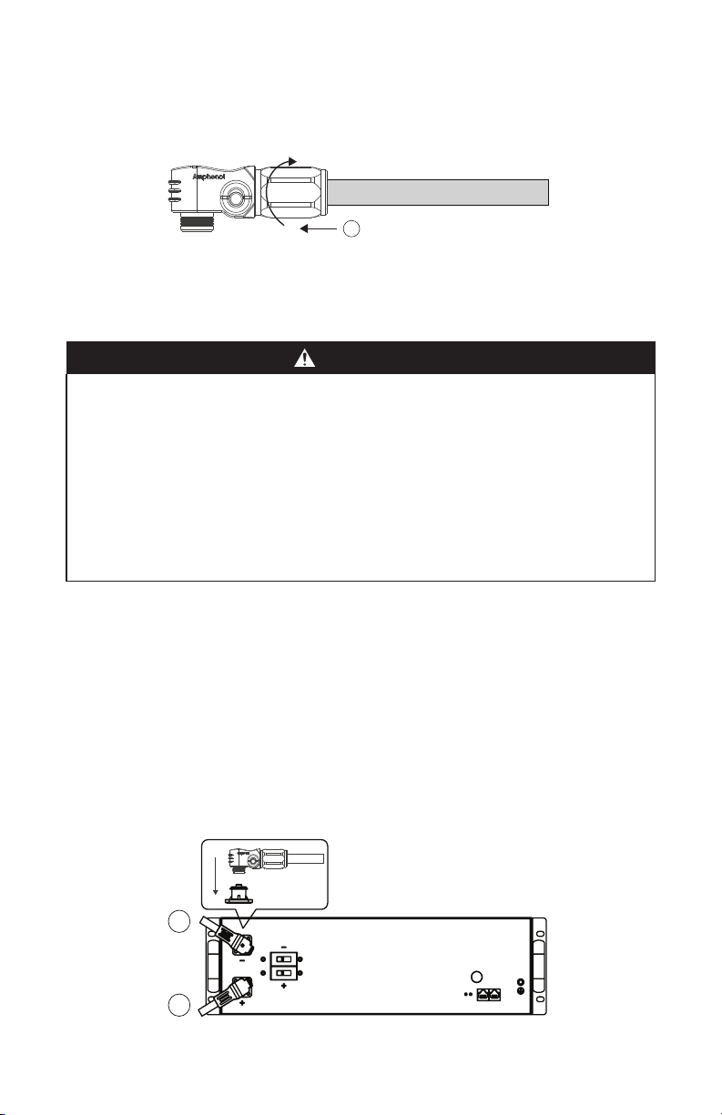
WARNING
ELECTRIC SHOCK AND FIRE HAZARD
Do not lay tools or other metal parts across battery terminals.
Failure to follow these instructions may result in death or serious injury.
CAUTION
ELECTRIC SHOCK HAZARD
• Do not touch the energized surfaces of any electrical component in the Battery
Module Combiner or Battery Module system.
• Before servicing, follow all procedures to fully de-energize the Battery Module
Combiner and Battery Module system.
• Follow “Safe Handling Procedures” when working with the Battery Module Combiner
or Battery Module system.
Failure to follow these instructions may result in injury.
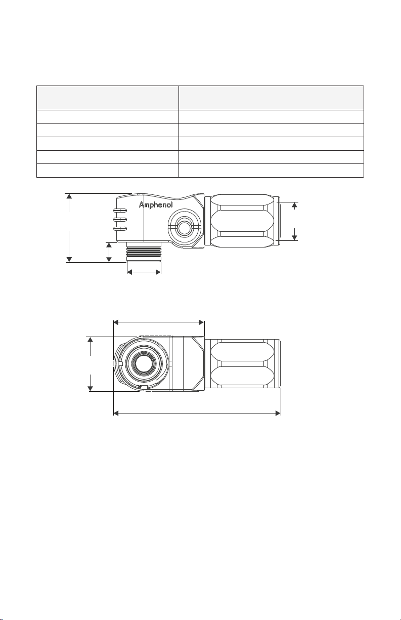
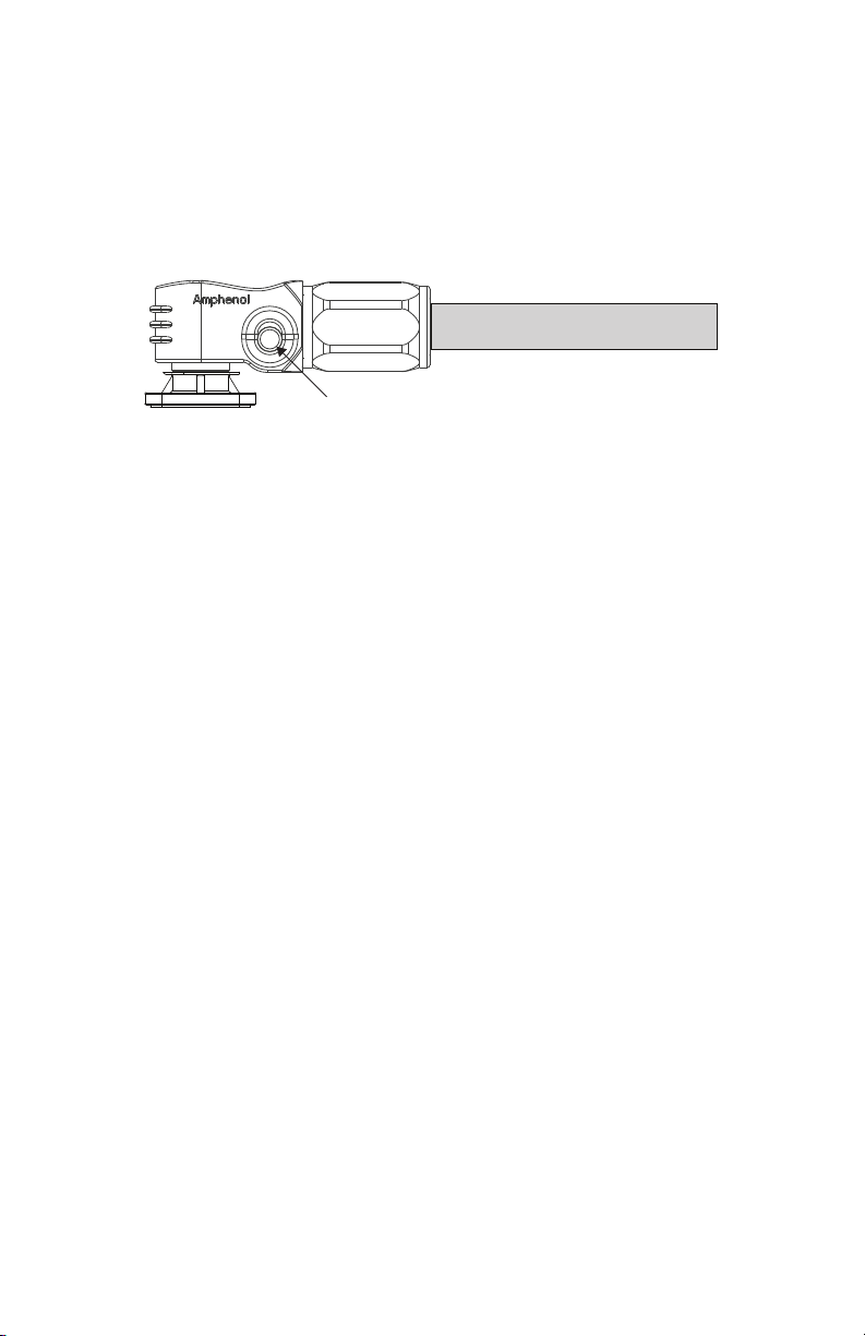
1.4 Safe Handling Procedures
Before using the Battery Cable Terminal Connector Set, read all instructions and
cautionary markings on the units and all appropriate sections of this manual.
• Use personal protective equipment when working with the Battery Cable
Terminal Connector.
• Dispose of or recycle a Battery Cable Terminal Connector following local
regulations.
• Do not modify, re-manufacture, or attempt to insert foreign objects into the
Battery Cable Terminal Connector.
• Do not immerse or expose the Battery Cable Terminal Connector to water or
other liquids, fire, explosion, or other hazards.
• Use the Battery Cable Terminal Connector only with AES RACKMOUNT Battery
Modules or equipment that Discover Energy Systems specifies as compatible.
• Do not lift or carry while in operation.
• Take precautions when handling electrical cables.
• Do not submerge the Battery Cable Terminal Connector.
• Do not install the Positive (Red) Battery Cable Terminal Connector on the
negative battery cable.
• Do not install the Negative (Black) Battery Cable Terminal Connector on the
positive battery cable.
• Do not use the Battery Cable Terminal Connector with Battery Modules or
equipment that exceeds the specifications. Using Battery Modules or equipment
that exceeds Battery Cable Terminal Connector specifications may present a fire
risk or other hazards.