INSTALLATION, OPERATION AND
MAINTENANCE INSTRUCTIONS
Save These Instructions
Document No.: 48-00003 Revision A Page: 10
PUMP SPEED AND HORSEPOWER
This unit is equipped with a gear reducer that turns the pump shaft
at a reduced speed relative to the motor shaft. It is available in
multiple speed (flow) and HP (pressure) options. Please see the
“Product Overview” section for details on the gear reducer and HP
specifications for your model to determine flow and pressure
performance. Be sure to take this into consideration when verifying
the applicability of this unit for pumping/filtration applications.
HOSE CONNECTIONS
Use of high quality camlock fittings with locking levers is
recommended to avoid hazardous spills.
REVERSE ROTATION
The FS1 SERIES systems are not designed to be operated in
reverse rotation.
PUMP BYPASS FEATURE
The pump end on this unit is a Dixon Pumps positive displacement
pump. Positive displacement pumps require a bypass mechanism to
relieve the pressure in the system when there is a blockage, valve,
or nozzle on the discharge side of the pump.
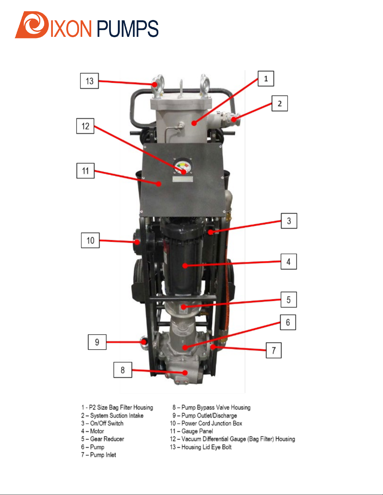
FILTER HOUSINGS – FILTER ELEMENT ACCESS
The filter housing is equipped with a removable lid that is secured
with four eye bolts. After relieving pressure in the system, the
housing lid can be removed by loosening all four bolts and
completely removing three of them. One of the eye bolts can be left
in place to hold the lid as it is rotated out of the way.
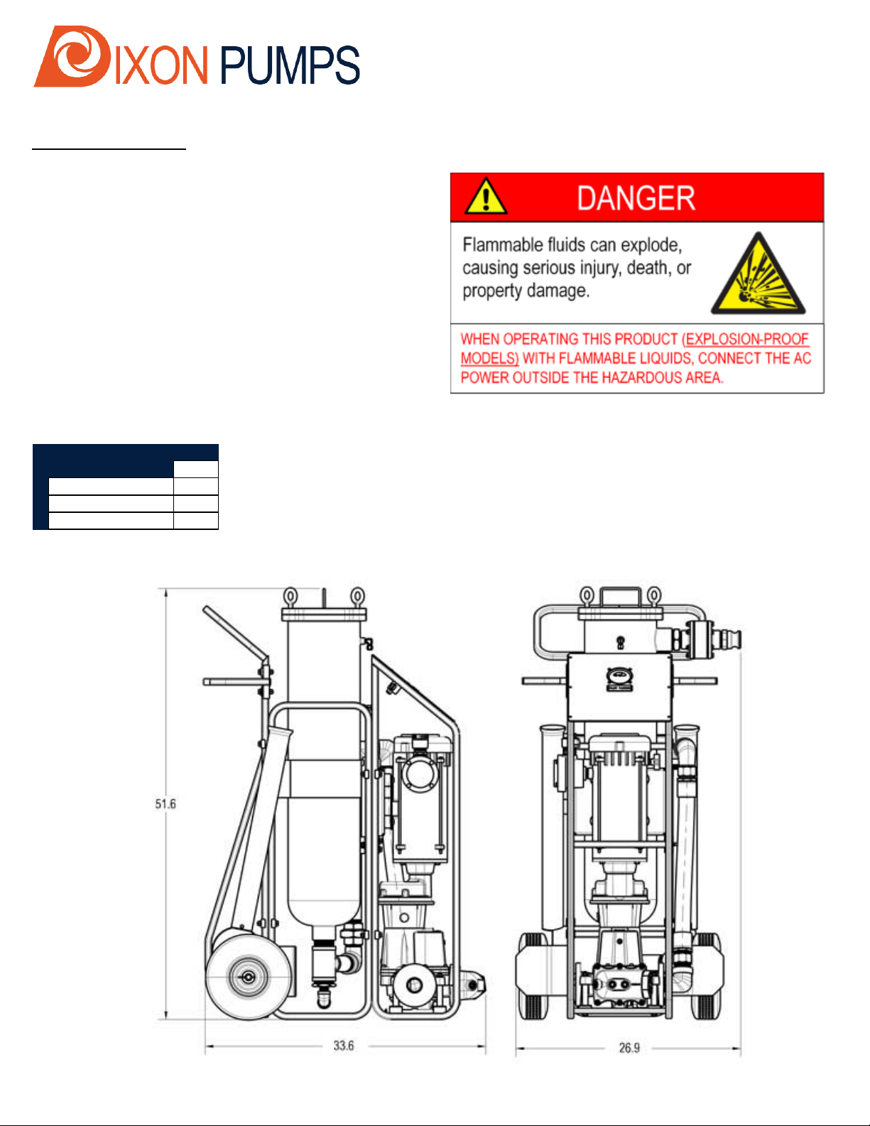
WHEN PUMPING FLAMMABLE LIQUIDS WITH
EXPLOSION-PROOF MODELS,
ALL HOSE COUPLINGS MUST BE EXPLOSION
PROOF RATED. ALL HOSE MUST HAVE A
STATIC WIRE, AND MUST ALSO BE UL LISTED
FOR CLASS 1, DIV 1, GROUP D, CLASS 2,
GROUP F AND G (CANADA: MUST BE CSA LISTED)
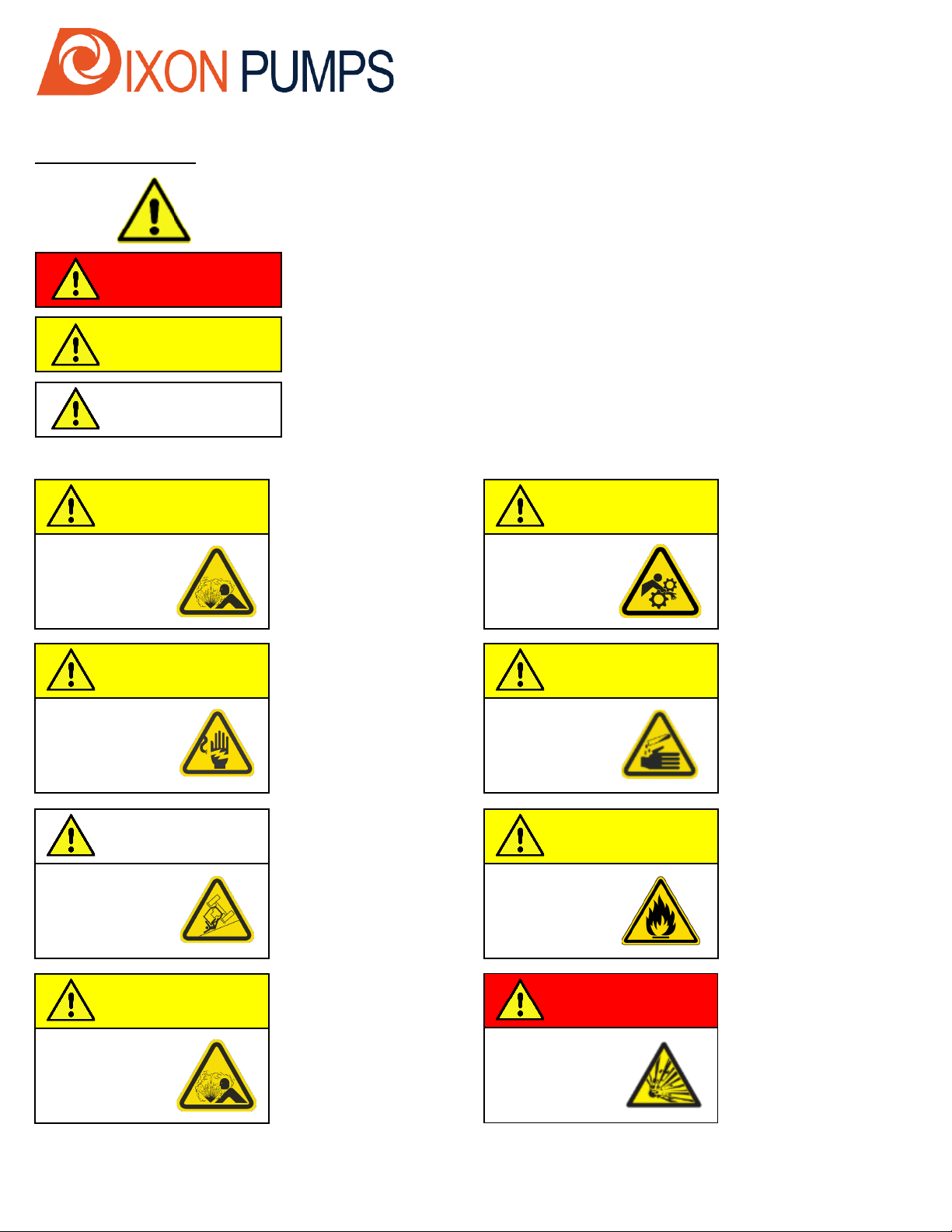
Flammable fluids can explode,
causing serious injury, death, or
property damage.
Flammable fluids can explode,
causing serious injury, death, or
property damage.
WHEN PUMPING FLAMMABLE FLUIDS SUCH AS
GASOLINE (NFPA CLASS I LIQUIDS) WITH EXPLOSION-
PROOF MODELS, DO NOT ALLOW THE PUMP TO STAY
IN BYPASS FOR LONGER THAN ONE (1) MINUTE.
WHEN CHANGING FILTERS, TIGHTEN FILTER HOUSING
LIDS BY HAND. DO NOT USE TOOLS ON FILTER
HOUSING EYE BOLTS. OVERTIGHTENING CAN RESULT
IN DEFORMATION OF THE CANISTER LID AND FAILURE
OF LIQUID-TIGHT SEAL!
Hazardous pressure can cause
personal injury or property damage
WHEN REPLACING FILTER ELEMENTS, MAKE SURE THE
PUMP IS OFF AND THE PRESSURE IS RELIEVED BEFORE
OPENING THE FILTER HOUSING LID.
WHEN USING A SHUT-OFF NOZZLE, THE PUMP WILL
OPERATE IN THE BY-PASS MODE (FLUID WILL
CIRCULATE AROUND INSIDE THE PUMP THROUGH THE
BYPASS FLOWPATH) IF THE NOZZLE IS IN THE “OFF”
(CLOSED) POSITION. THE PUMP SHOULD NOT BE
OPERATED FOR MORE THAN FIVE (5) MINUTES IN FULL
BY-PASS MODE FOR NFPA CLASS II AND CLASS III