Evoqua Neptune Benson Defender FP Series User manual
JOB# 35452
AND
INSTRUCTIONS
OPERATION
INSTALLATION
FOSS SWIM SCHOOL
AND
ACCESSORIES
ELMWOOD PARK
FILTER SYSTEM
an QUA brandevo
334 Knight St. Suite 3100, West Warwick, RI 02886 (800) 832-8002
(401) 821-2200 Fax: (401) 821-7129
E-mail: infowebsite.nb@evoqua.com www.neptunebenson.com

M.LYNCH 14DEC21
INIT DYMNYR
FOSS SWIM SCHOOL - ELMWOOD PARK
SWIMMING POOL
FOSS SWIM SCHOOL LLC
35452
1
1
-
1.18 GPM/SQ.FT
252 GPM
NTS


Page 2 | 26 Rev: 01/18/2021
TABLE OF CONTENTS
Introduction .................................................................................................................................................................3
Specifications..............................................................................................................................................................4
Safety............................................................................................................................................................................4
Installation ...................................................................................................................................................................5
Positioning the Filter..................................................................................................................................................5
Installing the Tank Anchors.......................................................................................................................................5
Installing the Gauge Panel ........................................................................................................................................6
Installing the Control Enclosure and Filter/Regulator................................................................................................7
Installing the Butterfly Valves ..................................................................................................................................10
Making the Pneumatic Actuator Tubing Connections .............................................................................................11
Adjusting the Pneumatic Actuators .........................................................................................................................14
Vacuum Transfer Unit Installation ...........................................................................................................................16
Operation ...................................................................................................................................................................17
System Requirements .............................................................................................................................................17
Pre-Startup Check...................................................................................................................................................17
Performing a Dry Test .............................................................................................................................................17
Performing a Quick Start.........................................................................................................................................18
Loading Media into the System (Precoat Process) –Vacuum Transfer .................................................................18
Entering Filtration Mode ..........................................................................................................................................19
Performing the Power Bump Sequence..................................................................................................................19
Recharging the Media .............................................................................................................................................19
Maintenance...............................................................................................................................................................20
General Maintenance ..............................................................................................................................................20
Indoor Pool Chemical Cleaning Frequency.............................................................................................................20
Outdoor Pool Chemical Cleaning Frequency..........................................................................................................20
Suggested Chemicals..............................................................................................................................................21
Chemical Clean Procedure......................................................................................................................................21
Flexible Tube Element Wash Procedure.................................................................................................................22
Parts List Assembly..................................................................................................................................................23
Exploded View.........................................................................................................................................................23
Parts List..................................................................................................................................................................24
Diffuser Assembly....................................................................................................................................................25
Head Loss Chart......................................................................................................................................................26

Page 3 | 26 Rev: 01/18/2021
INTRODUCTION
Figure 1: Power Bump Regenerative Media Filter Schematic
Mark
Reference
V1
Effluent valve
V2
Power bump valve
V3
Power bump valve
V4
Power bump valve
V5
Precoat valve
V6
Vacuum transfer valve
V7
Vacuum vent valve
V8
Vacuum hose valve
V9
Tank drain valve
V10
Check Valve (4” or 6”)
V11
In-line sight glass
Mark
Reference
F1
Pump base
F2
Pump
F3
Reducer
F4
Precoat tee
F5
Strainer
F6
Precoat Line Vent Valve
F7
Pump Throttling Valve

Page 4 | 26 Rev: 01/18/2021
SPECIFICATIONS
Filter Media
Perlite
Media Regeneration Method
PowerBump™
Filtration Area
212 ft2 (19.7 m2)
Minimum Flow Rate
107 gpm (24 m3/hr)
Maximum Flow Rate
300 gpm (68 m3/hr)
Maximum Allowable Water Pressure
50 psi (3.45 Bar)
Required Air Pressure
90-110 psi (6.2 –7.6 Bar)
Maximum Water Temperature
104°F (40°C)
Maximum Ambient Temperature
110°F (43°C)
Minimum Ambient Temperature
0°F (-17°C) (Above 36°F when full of water)
Controller Power
110/230 VAC 15/10A 50-60Hz
Drain Line
100 gpm (23 m3/hr) Surge Flow (atmospheric)
Installation Location
Indoor/Outdoor
SAFETY
The Defender FP-Series RMF is a system designed to run 24/7 with limited supervision. Ensure that all precautions are
taken to maintain the safety of operators or service technicians and restrict access to unauthorized personel.
Inhalation hazard may be present when loadng Perlite media. Minimize dust exposure through
proper handling and wear respiratory PPE if necessary.
The potential of skin burn injury exists when handling or servicing the pnuematic actuators and
pump when on or shortly after stopping the system. Use caution around the system and avoid
the heated areas during operation. Use personal protective equipment to prevent burns if
necessary.
A potential hearing hazard exists when pumps and compressors are in operation. Repair
malfunctioning equipment immediately and install sound absorbing protective measures if
necessary.
Potential electrical hazards exist when servicing the local control panel and pumps. Always
isolate electrical power supplies before servicing powered equipment and devices. After isolating,
ensure power has dissipated from circuit components before accessing panels and equipment.
Exercise caution around pools of water that may have become electrified.
Potential slip hazards exist over the lifetime of operating equipment. Wear slip resistant shoes
and repair leaking connections or piping immediately.
A potential moving parts hazard exists when servicing or inspecting centrifugal pumps or
actuated valves. Turn off control to pumps and valves before servicing. Do not operate without
guards in place.
Page 5 | 26 Rev: 01/18/2021
INSTALLATION
The following sections cover the positioning of the filter, installing the tank leg anchors, gauge panel, the control enclosure
and the filter/regulator, connecting the pneumatic actuator tubing, and adjusting the pneumatic actuator.
WARNING
Use of personal protective equipment (PPE) is necessary for the installation and maintenance procedures outlined in this manual.
Safety glasses and safety shoes should be worn for all maintenance procedures. Exercise caution around pressurized air lines,
electrical hazards, and potentially slippery surfaces when wet.
Positioning the Filter
Position the filter using one of the following methods:
a. Use the two eye bolts to lift the filter into position.
b. Use a hand truck to position the filter.
Installing the Tank Anchors
WARNING
The FP Series RMF filter is equipped with mounting anchors to secure it to the floor. Anchors must be installed per the manufacturer’s
instructions before attempting to lift the filter head (top plate). Failure to properly bolt the filter to the floor can result in bodily injury and
equipment damage.
Figure 2: Tank Anchor Installation Locations
1. With the filter tank in its installed location, use a 0.5 inch carbide-tipped concrete drill bit to drill a 2.625 inch hole in
the floor. There should be 3 inches of depth from the top of the saddle base.
2. Remove all concrete dust from the holes.
3. Place the washers and nuts on the anchor.
4. Insert the anchor through the floor base into the hole.
5. Being careful not to damage the threads, hammer the anchor into the hole as far as it will go.
6. Repeat Steps 3 and 4 for all six anchor locations.
7. Tighten all six bolts to 60 lbf.-f (81 N-m).
NOTE
In order to conform with the ASCE 7-16 Seismic Design criteria, anchor bolts must be installed at least 10 inches (25.4 cm) from the
edge of a concrete pad that is more than 6 inches (15.2 cm) deep. Failure to follow these guidelines will compromise seismic integrity.

Page 6 | 26 Rev: 01/18/2021
Installing the Gauge Panel
Figure 3: Gauge Panel
1. Remove two (2) adjacent bolts from the top cover in your desired location to make the pressure gauges easily visible.
2. Install the 6 inch bolts (provided) in the empty bolt holes and torque to 55 ft-lbs (75 N-m).
3. Install the gauge panel mounting bracket by inserting the longer flange bolts through the channel in the bracket and
secure with 0.75 inch nuts (included)
4. Bolt the gauge panel to the mounting bracket using four 0.25 x 1 inch screws, washers, and nuts (included).
5. Connect 0.25 inch tubing (included) to the gauges using the compression connectors (included)
6. Connect the tubing to the influent and effluent piping as close to the filter as possible.
0.25 x 1
inch screws
0.25 inch OD
tubing (included)
0.25 inch male compression
connector (included)

Page 7 | 26 Rev: 01/18/2021
Installing the Control Enclosure and Filter/Regulator
Figure 4: Control Enclosure and Filter/Regulator
0.5 inch hard pipe
from compressor
Do not use PVC
(not included)
0.5 inch shut off
valve (not included)
0.5 inch
instant fitting
0.5 inch hose
to solenoid
Manifold block
Tubing to valves (included)
See pneumatic tubing installation
Filter/Regulator

Page 8 | 26 Rev: 01/18/2021
Control Enclosure
WARNING
It is the responsibility of the end user to adhere to all regulations regarding electrical equipment installation. Ensure all parts are
properly grounded, safe from water intrusion and has a proper disconnect. Consult a licensed electrician.
1. Mount the control enclosure at eye-level to a wall using anchors compatible with the type of wall construction; block,
plaster, wood, etc. The anchors are not included.
NOTE
When mounting the control enclosure, ensure that there is enough clearance for the pneumatic tubing from the compressor to the panel
and the pneumatic tubing from the panel to the valves.
2. Power to the control panel should be provided by a disconnect with GFCI and overcurrent protection supplied by
others. Recommended protection is 120/230 VAC, 15/10 A.
•Line Power: Connect to TERMINAL 100.
•Neutral: Connect to TERMINAL 100A.
•Ground: Connect to GROUND LUG (located at the upper right corner of the panel).
3. Connect the dry contact run signal and return signal from pump
•Terminals 232 and 232A provide a (NO) dry contact signal to be sent to the pump when the filter is on
•Terminal 205 can be used to return a (NC) +24V DC signal from the pump to indicate the pump is running
NOTE
If no return signal is available from your pump to indicate no fault, a jumper will need to be installed. Use a small piece of wire to
connect terminals 110 and 205. If this is not done, the controller will interpret a fault.
Figure 5: Field wiring diagram
WARNING
The control enclosure can be supplied with either 120/230 VAC which is a danger to life. Lock out and tag out (LOTO) the electrical
disconnect supplying the controller before servicing.
Page 9 | 26 Rev: 01/18/2021
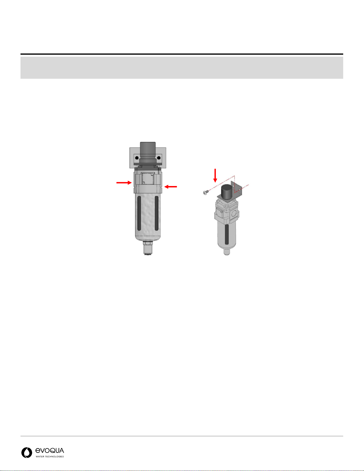
Filter/Regulator
NOTE
2.6 CFM at 90 psig of Clean/Dry air is required to maintain the life of the solenoid valves and pneumatic actuators. A Filter/Regulator
and Water Separator can be sourced independently or purchased through Neptune Benson. Failure to use these items will void the
warranty of affected parts.
1. Attach the filter/regulator to a wall using anchors compatible with the type of wall construction, Block, plaster, wood,
etc. The anchors are not included.
2. Add an isolation valve before the filter/regulator. Mount the valve on the wall
3. Use iron piping, galvanized piping, or an air hose (not PVC) to connect the compressor to the filter/regulator.
4. Connect the line from the compressor to the filter/regulator.
5. Connect the filter/regulator to the manifold tab.
Figure 6: Filter/Regulator/Water Separator Unit
1
2
3
Page 10 | 26 Rev: 01/18/2021
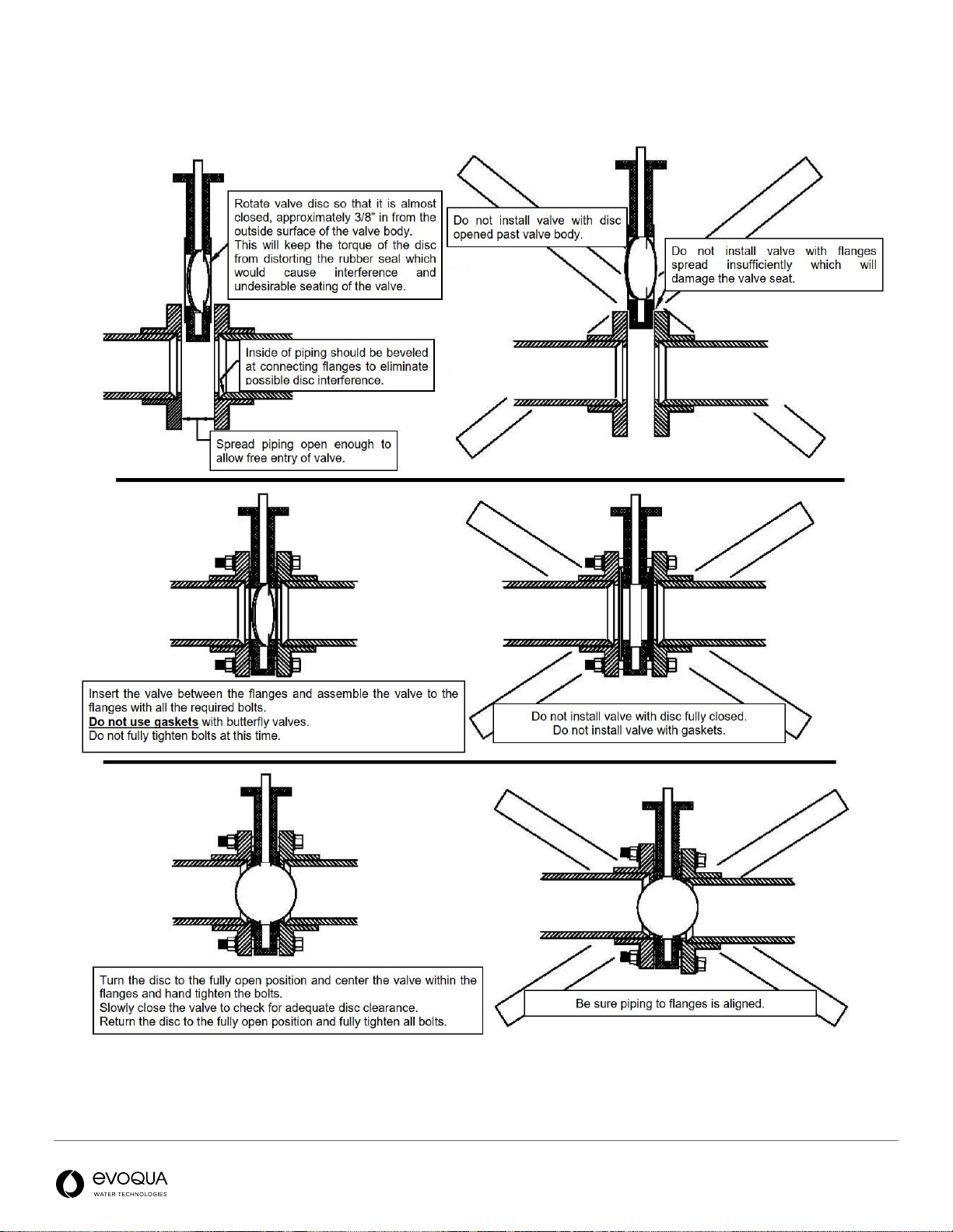
Installing the Butterfly Valves

Page 11 | 26 Rev: 01/18/2021
Making the Pneumatic Actuator Tubing Connections
Figure 7: Pneumatic Tubing Diagram
Page 12 | 26 Rev: 01/18/2021
Figure 8: Solenoid manifold tube connections
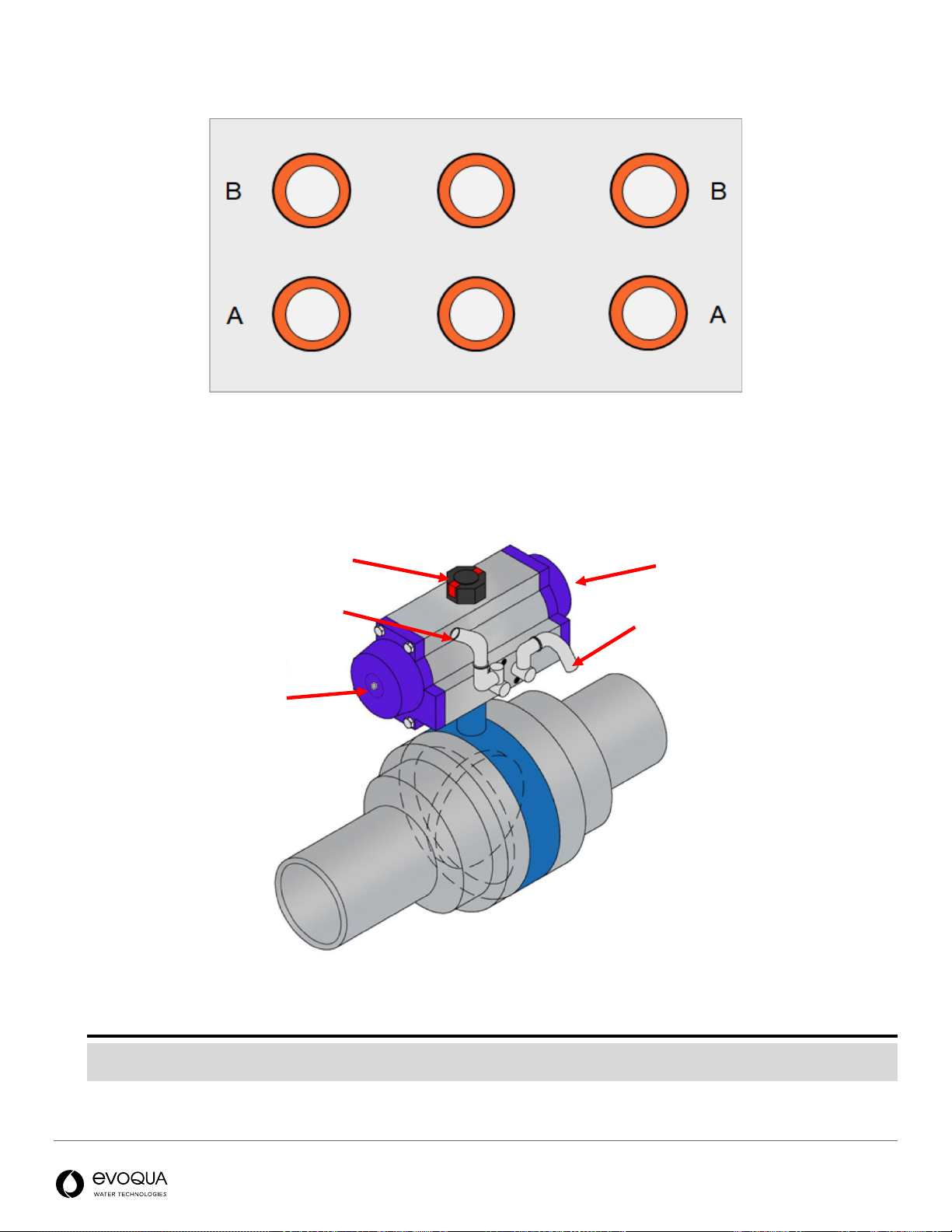
Figure 9: Pneumatic Actuator Setup
NOTE
Standard actuators for the Defender FP are Rotork pneumatic actuators as included in valve kit 1002-1214/1002-1543. If using
any other actuator, consult your system designer on proper actuator installation.
Air to OPEN valve
Valve disc position indicator
Air to CLOSE valve
Open (silver)
adjustment
Closed (gold)
adjustment
V2-Open & V3-Closed & V4-Open
V2-Closed & V3-Open & V4-Closed
V5-Closed
V5-Open
V1-Open
V1-Closed
Page 13 | 26 Rev: 01/18/2021
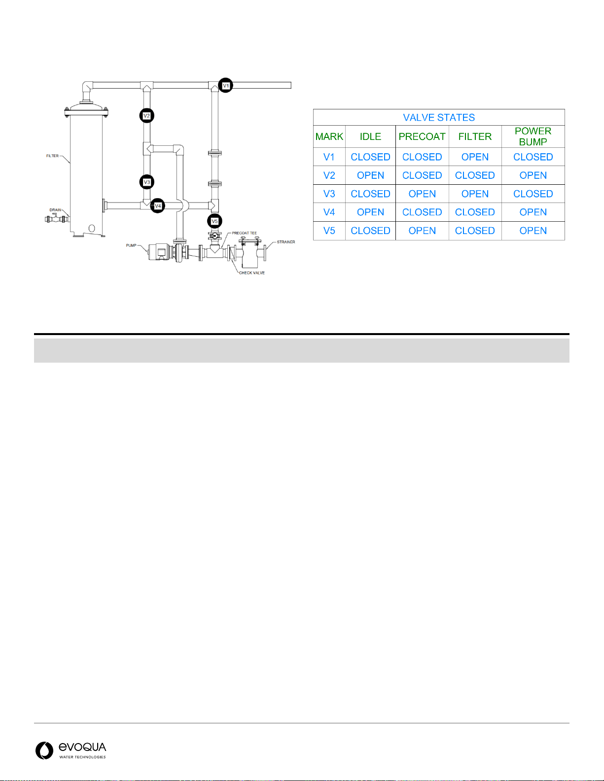
Figure 10: Valve position and state matrix
NOTE
After making pneumatic actuator connections, raise the air pressure to 90 psi and confirm the valve positions match the “Idle” state
presented in the valve matrix table above. If a valve state is incorrect, reverse the tubing between the top and bottom port.

Page 14 | 26 Rev: 01/18/2021
Adjusting the Pneumatic Actuators
Actuator Mounted Parallel with the Piping (Recommended)
1. Ensure the actuator is de-pressurized before making any adjustments, by turning the Filter/Regular knob
counterclockwise until the pressure reads 0 psi. Make all adjustments on the outside of the actuator.
2. To make the closing adjustment, loosen the gold nut. Turn the stop pin outwards counterclockwise to the limit closing
to less than 100%.
NOTE:
The right-side Silver Nut is for Open adjustment clockwise rotation. Opening adjustment is not typically required.
Flow (Speed) Control Valves Adjustment
Figure 11: Flow Control Valves
Pneumatic actuators are provided with the flow control valves. The flow control valves connected to the pneumatic
actuators are used to regulate the speed of the butterfly valve operation. To adjust the speed of the butterfly valves:
1. Shut off the air supply.
2. Remove the tubing from the closed port of the pneumatic actuator. Refer to the above to determine which port is the
closed port.
3. Connect the tubing to the air supply in on the air switch.
4. Remove the tubing from the open port of the pneumatic actuator.
5. Connect the tubing from the air switch to both ports of the pneumatic actuator.
6. Open the air supply.
7. Move the switch to both the open and closed positions to verify proper operation of the valve in both positions.

Page 15 | 26 Rev: 01/18/2021
If necessary, adjust the valves. To adjust the valves:
1. Loosen the lock nut, and then close the control valves by turning them clockwise.
2. Open each valve 1.5 turns counterclockwise.
If necessary, adjust the valves for smooth operation. To make this adjustment:
1. The control valve on the closed port regulates the butterfly valve’s opening speed.
2. The control valve on the open port regulates the butterfly valve’s closing speed.
3. Closing the valves slows the speed of the butterfly valve.
4. Opening the valves increases the speed of the butterfly valve.
NOTE:
Make sure to remove the flow control valve before returning the system to normal operation.
Page 16 | 26 Rev: 01/18/2021
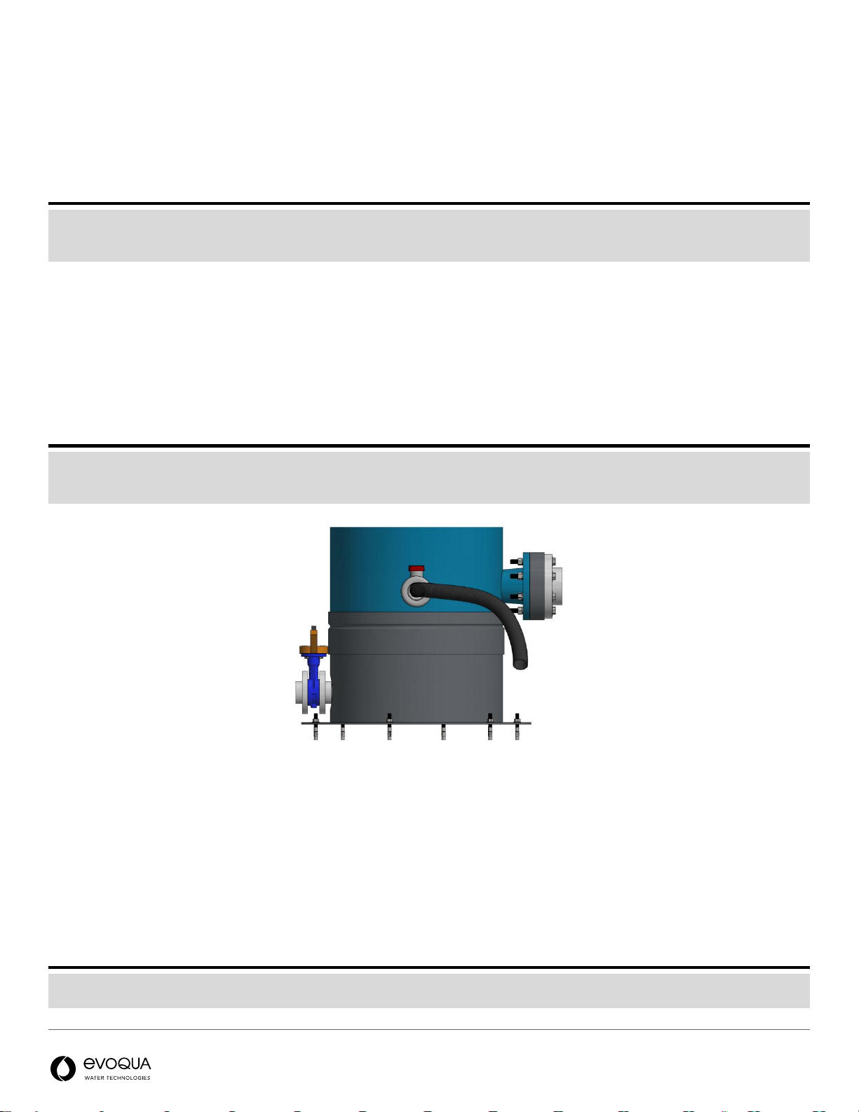
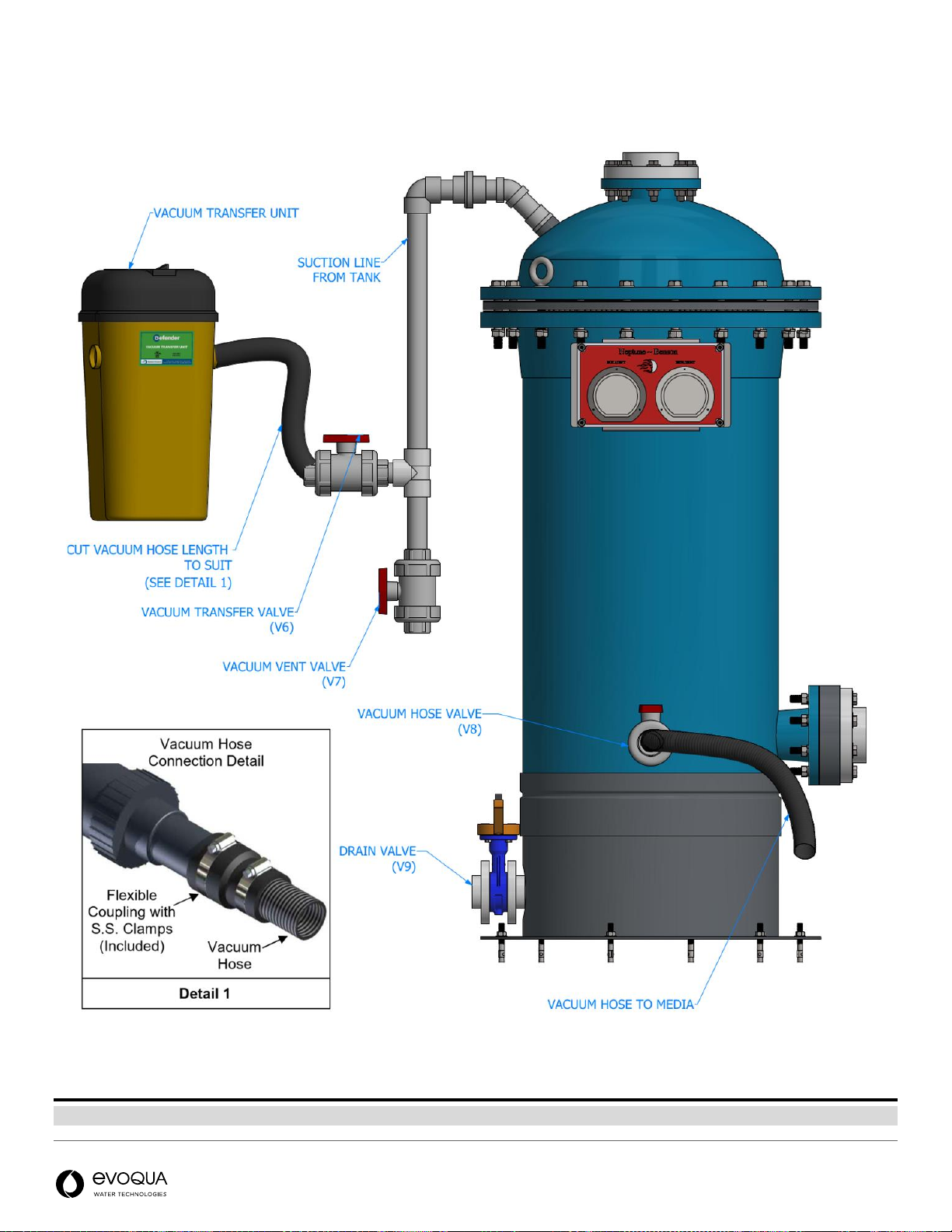
Vacuum Transfer Unit Installation
Figure 12: Vacuum transfer setup
NOTE:
Most standard shop style vacuums will be appropriate for loading media. A vacuum can be provided by Neptune Benson on request.

Page 17 | 26 Rev: 01/18/2021
OPERATION
The following sections describe system requirements, the pre-startup check, dry testing procedure, quick start
instructions, loading/recharging media, filtration mode and PowerBump sequence.
System Requirements
•Water supply
•Air supply: Pressure should be a minimum of 90 psi (6.2 Bar)
•17 lb.(7.7 kg) of perlite (EWT Part Number: 1000-5852)
NOTE
Defender® filters are designed to operate with perlite media. Use of any other media may compromise filter performance.
NOTE
To drain the system, isolate the filter unit from the pool and then open drain valve V9. Vent valve F6 can be opened to increase the
drain rate.
Pre-Startup Check
NOTE
All plumbing and valving must be installed per the filter schematic. Refer to Introduction.
1. Verify power is supplied to the following items prior to scheduling a start-up:
•Compressor
•Control Panel is wired (Refer to Installing the Control Panel and Filter Regulator)
•Set the filter/regulator to 90 PSI (6.2 Bar).
•Pump rotates in the proper direction and is ready to run
Performing a Dry Test
2. With the pump off, connect jumper between terminal 110 (+24V) and terminal 205 (NC pump fault signal)
3. Turn the switch on the Control Panel to Filter Mode and then press the Bump button
4. Ensure all valves transition smoothly without slamming open or closed (Refer to Adjusting the Pneumatic Actuators)
5. Confirm that the valve states correspond to Figure 10 in all modes.
6. Turn the switch on the control panel to OFF
7. Remove the jumper and proceed with startup.
Check for air leaks at the tubing connections. If leaks occur:
1. Turn the compressor off.
2. Remove the tubing. Verify it is cut square and free of defects.
3. Reinstall the tubing. Pull to ensure it is connected securely.
If leaks still occur:
The tubing might be the incorrect OD (outer diameter). All tubing is to be imperial and 0.5 inch O.D.and 0.25 inch.O.D.
Refer to Installing the Control Enclosure and Filter/Regulator.

Page 18 | 26 Rev: 01/18/2021
Performing a Quick Start
Once initial preparation is completed, the unit is ready to be started. For start-up to work properly, shut down all auxiliary
equipment (including pumps). Place the unit into idle by turning the switch on the PowerBump Control Panel to the left
(OFF).
Loading Media into the System (Precoat Process) –Vacuum Transfer
Refer to the schematic found in Introduction.
NOTE
While loading media, it is recommended to wear safety glasses and a dust mask. Perlite is non-hazardous but a fine powder that could
cause irritation.
NOTE
The filter vessel must be fully drained prior to beginning this process.
1. Ensure the system is OFF and the pump is ready to run
2. Close pump discharge throttling valve F7
3. Open vacuum drain valve V7 to drain any water in the vacuum transfer piping.
4. Close vacuum drain valve V7.
5. Open vacuum transfer valve V6 and vacuum hose valve V8.
6. Verify tank drain valve V9 is closed.
7. Turn vacuum on and vacuum 17 lb. (7.7 kg) of perlite media into the filter tank.
8. Turn vacuum off.
9. Close vacuum hose valve V8 and vacuum transfer valve V6.
10. Open the 0.75 inch precoat vent line valve F6 and 1.5 inch vacuum drain line valve V7.
11. Open pump discharge throttling valve F7 and purge the air from the system.
NOTE
If the filter is below grade, it starts to fill automatically. If the filter is above grade, start the pump manually. As the tank is filling, air is
escaping from both the 1.5 inch vacuum drain valve and the 3/4 inch precoat vent line valve F6.
12. As soon as a steady stream of water exits this line, close the vacuum drain valve V7 and close the precoat vent line
valve F6.
13. Turn the switch on the PowerBump Control Panel to the right (ON) to run the pump and start the
precoat/regeneration process.
After 5 seconds the precoat valve V5 opens to start the precoat/regeneration process. After 10 minutes, the effluent valve
V1 will open. The precoat valve V5 will close 15 seconds later. The system is now in Filter Mode.
14. After initial precoat is completed, press the Bump button. This ensures an even precoat and only needs to be done
after loading media.
NOTE
On initial filter start-up, drain and recharge the media as soon as the pool water is clear. This will rid the filter of construction debris and
contaminants. If the pool make-up water is extremely dirty, additional draining and media recharge might be required.
This manual suits for next models
1
Table of contents
Other Evoqua Water Filtration System manuals


Popular Water Filtration System manuals by other brands


HEISSNER
HEISSNER FPU24000-00 Instructions for use

Parker
Parker MV060 user guide

Culligan
Culligan WH-S100-O Installation and operation instructions

AREBOS
AREBOS AR-HE-SA/G/S Original user manual

Water Right
Water Right UltroWater Installation, operation & service manual

Parker
Parker Zander WS Series operating instructions

AQUA SZUT
AQUA SZUT AQUA 2 instruction manual

Miltenyi Biotec
Miltenyi Biotec autoMACS Pro user manual

Judo
Judo PROFI JPF DN125 Installation and operating instructions

Miele
Miele DFKS-A-1 Operating and installation instructions

Axeon
Axeon LT-200 user manual

Beko
Beko CLEARPOINT S055 Instructions for installation and operation