Dixon FloTech FT295 Operating and maintenance manual

Maintenance & Operating
Instructions
For
FloTech
FT295 ALARM INTERFACE
10847PA REV B
Dixon Bayco Division
Cincinnati, Ohio

FT295 10847PA REV B Page 2
Contents
Contents .....................................................................2
What’s in the Box........................................................3
Introduction.................................................................3
Main Features.............................................................4
Specifications .............................................................4
Installation ..................................................................5
Operation....................................................................6
Mounting Dimensions.................................................7
Wiring Diagram...........................................................8
Example External Connections................................10
Maintenance.............................................................13
Replacement Parts...................................................13
Dixon Warranty:........................................................13
Technical Support Hotline........................................14

FT295 10847PA REV B Page 14
Technical Support Hotline
(877) 582-3569
Contact the FloTech Technical Support Hotline for
help:
•Troubleshooting overfill systems.
•Verifying defective components
•To request an RGA for defective FloTech
products under warranty.
For Sales & Service Contact
USA: Canada:
Dixon Bayco USA Dixon Group Canada Limited
Chestertown, Maryland Innisfil (Barrie), Ontario
Phone: 410-778-2000 Phone: 705-436-1125
Fax: 410-778-4702 Fax: 705-436-6251
Toll Free: 800-355-1991 Toll Free: 877-963-4966
E-mail: dixonbayco@dixonvalve.com E-mail: isales@dixongroupcanada.com
www.dixonbayco.com www.dixongroupcanada.com
Mexico Europe
Dixva, S. de R.L. de C.V. Dixon Group Europe Ltd
Monterrey, N.L Preston, England
Phone: 01-800-00-DIXON (34966) Phone: +44 (0)1772 323529
Fax: 01-81-8354-8197 Fax: +44 (0)1772 314664
E-mail: contactenos@dixonvalve.com.mx E-mail:enquiries@dixoneurope.co.uk
www.dixonvalve.com www.dixoneurope.co.uk
Asia Pacific
Dixon (Asia Pacific) Pty Ltd
Wingfield, South Australia
Phone: +61 8 8202 6000
Fax: +61 8 8202 6099
E-mail: enquiries@dixonvalve.com.au
www.dixonvalve.com.au
FT295 10847PA REV B Page 3
What’s in the Box
Part Quantity
•FT295 Alarm Interface Main Unit......................1
•½”MIP by 1/2” strain relief.................................2
•Pipe plug ...........................................................1
•Instruction manual.............................................1
Introduction
Tank trailers featuring overfill prevention monitors are
often restricted to having the monitor installed in select
positions on the trailer due to sensor cabling. The
limited install locations may not cater to the driver or
rack operator and restrict the trailer from use in certain
situations. The FT295 serves as a remote view of the
onboard monitor’s loading permit state, offering greater
flexibility and functionality than a standalone monitor.
In addition to offering a secondary location to view the
onboard monitor’s permit state, the FT295 also
features an alarm to notify driver or rack operators
when a monitor enters a non permissive state.
It is common that trailer overfill protection systems
require the onboard monitor’s relay output contacts to
control external devices such as lights, motors, or
solenoids. The current or voltage rating of the
monitor’s output relay may not be sufficient to control
these devices directly. In these cases the FT295 can
be used as a pass through device effectively raising
the limitations of the monitor’s output relay. The FT295
relay contacts are suitable for switching a heavy load.

FT295 10847PA REV B Page 4
Main Features
•Designed for use with all onboard overfill
prevention monitors featuring relay output
contacts.
•Features an audible alert to indicate the
permissive state of the onboard monitor.
•LED indicators to reflect the power and permit
state of the connected monitor.
•2 Amp, 120/240VAC, 30VDC Relay outputs to
reflect output of monitor relay, making the FT295
serve as a pass-through device.
•Connections available for interfacing external 12V
indicators including buzzers and lights.
•Used to further extend monitor output and
functionality.
•Water-tight enclosure suitable for outdoor
mounting.
•Power switch to enable/disable device.
Specifications
•Dimensions ...........................4.55” x 6.65” x 10.27”
•Supply voltage.............................................12 VDC
•Relay coil voltage.....................................6-12 VDC
•Relay coil current ........................................150 mA
•Relay contact config.......................................4PDT
•Relay contact rating ...........................................2 A
•Fuse 1 rating...............................................500 mA
•Fuse 2 rating......................................................2 A
•Fuse 3 rating......................................................2 A
FT295 10847PA REV B Page 13
Maintenance
The FT295 is designed for long term outdoor use and
requires little maintenance when installed properly.
Regularly ensure that the lid screws and cable glands
are tight creating a water tight seal. This will help
protect the internal circuitry from corrosion and extend
the life of the FT295.
Additionally, the FT295 contains a corrosion inhibitor
that can be replaced yearly to further protect against
corrosion due to moisture within the enclosure.
Replacement Parts
Specified fuses must be used to ensure intrinsically
safe operation of the FT295.
Designation F1 F2,F3
Dixon P/N 10848 10849
Mfg. P/N 7022.057 23112000029
Manufacturer SCHURTER LITTLEFUSE
Rated Current 500mA 2A
Rated Voltage 500VAC 500VAC
Material Ceramic Ceramic
Opening Speed Super QuickActing Super QuickActing
Quenching Mtl.
Sand
Sand
Dixon Warranty:
For warranty Information, please refer to the inside
back cover of the latest Dixon catalogue.

FT295 10847PA REV B Page 12
Example External Connections
FT295 10847PA REV B Page 5
Installation
Required Tools and Supplies
•#2 Flat head screwdriver
•#1 Flat head screwdriver
•3/8” Nut Driver/Socket
•18 AWG 4 conductor cable
•3/8” stainless steel Bolt/Lockwasher/Nut set
Procedure:
1. Determine desired install location.
2. Verify install location has sufficient room to open lid
and run cabling to FT295.
3. Drill mounting holes to align with two mounting
holes on FT295, referring to Figure 1 for mounting
dimensions.
4. Mount FT295 using 3/8” bolts, lock-washers, and
nuts.
5. Open the front panel of the FT295 by loosening the
four front screws.
6. Disconnect the trailer nose piece and verify that the
12V line is discharged.
7. Connect the onboard monitor to the FT295 using
four conductor cable, referring to Figure 2 for wiring
diagram.
8. Tighten the cable gland holding the 4 conductor
cable to create a water-tight seal.
9. Make external connections to FT295, using TB2 as
needed, referring to Figure 2 for wiring diagram.
If no external connections are made to TB2 then
insert the included pipe plug.
Otherwise tighten the cable gland to create a
water-tight seal.

FT295 10847PA REV B Page 6
10.Move the ‘Cover Power Switch’ jumper on the
circuit board to enabled or disabled, to enable or
disable the front power switch, respectively.
Disabling the front power switch will cause the
FT295 to be on any time the 12V supply is on.
Enabling the front power switch will allow the
user to turn the FT295 on and off using the front
power switch.
11.Close lid and tighten four front screws.
12.Reconnect trailer nose piece and verify 12V line
voltage.
Operation
1. While onboard monitor is operating, toggle front
power switch to ON position.
2. LED indicators will match permit and power
indicators of onboard monitor.
3. The FT295 will make a sound while monitor is
non-permissive.
4. When finished toggle the front power switch to the
off position.
FT295 10847PA REV B Page 11
See examples on PG 12

FT295 10847PA REV B Page 10
Figure 2: Wiring FT295 to onboard monitor
with float relay outputs
FT295 10847PA REV B Page 7
Mounting Dimensions
Figure 1: Mounting Dimensions
FT295 10847PA REV B Page 8
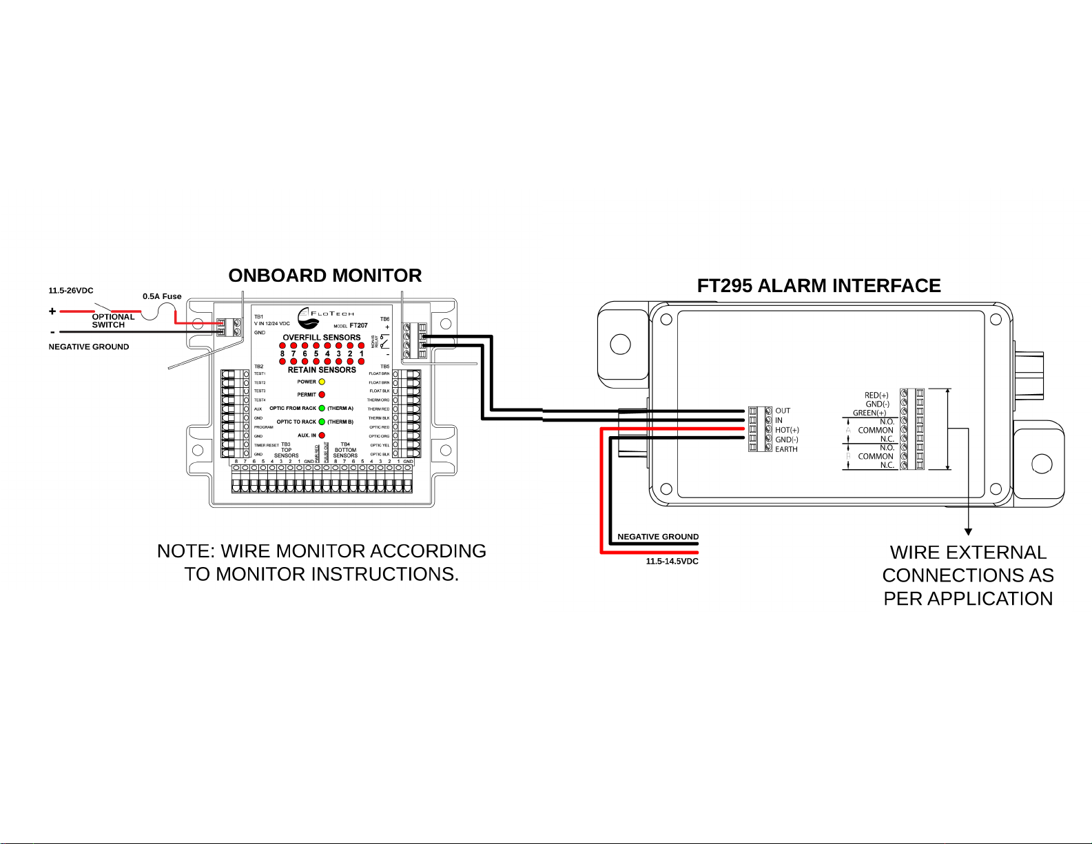
Wiring Diagram
Figure 2: Wiring FT295 to onboard monitor
with NON-IS relay outputs
FT295 10847PA REV B Page 9
See examples on PG 12
Table of contents


